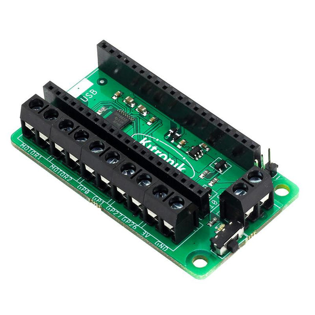
This board allows the Raspberry Pi Pico (connected via pin header) to drive two motors simultaneously with full forward, reverse & stop control, making it ideal for Pico controlled buggy projects. Alternatively, the board can be used to power a stepper motor. The board features the DRV8833 motor driver IC, which has built-in short circuit, over current and thermal protection.
The board has 4 external connections to GPIO pins and a 3 V and GND supply from the Pico. This allows for additional IO options for your buggy builds that can be read or controlled by the Pico. In addition there is an on/off switch and power status LED, allowing you to see at a glance if the board is powered up and save your batteries when your project is not in use.
To use the motor driver board, the Pico should have a soldered pin header and be inserted firmly into the connector. The board produces a regulated supply that is fed into the 40-way connector to power the Pico, removing the need to power the Pico directly. The motor driver board is powered via either screw terminals or a servo style connector.
Kitronik has developed a micro-python module and sample code to support the use of the Motor Driver board with the Pico. This code is available in the GitHub repo.
Features
A compact yet feature-packed board designed to sit at the heart of your Raspberry Pi Pico robot buggy projects.
The board can drive 2 motors simultaneously with full forward, reverse, and stop control.
It features the DRV8833 motor driver IC, which has built-in short circuit, over current and thermal protection.
Additionally, the board features an on/off switch and power status LED.
Power the board via a terminal block style connector.
The 3V and GND pins are also broken out, allowing external devices to be powered.
Code it with MicroPython via an editor such as the Thonny editor.
Dimensions: 63 mm (L) x 35 mm (W) x 11.6 mm (H)
Download
Datasheet
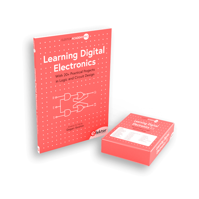
With 20+ Practical Projects in Logic and Circuit Design
This book is a practical guide to digital electronics, covering the essential components of modern digital systems: number systems, logic gates, Boolean algebra, combinational and sequential logic, and more.
Through more than 20 structured projects, you’ll design and build digital systems using real-world components such as logic gates, multiplexers, decoders, flip-flops, counters, and shift registers. The projects range from basic LED logic circuits to digital locks, display systems, traffic light controllers, and timing-based designs.
Selected projects introduce the use of tools such as CircuitVerse for circuit simulation, while several designs make use of 74HC-series logic devices, commonly used in digital hardware prototyping.
Inside, you’ll find:
Clear coverage of number systems and binary arithmetic
Logic gate fundamentals and universal gate implementations
Step-by-step projects using flip-flops, counters, and registers
Real-world design with 74HC-series logic chips
Techniques for designing combinational and sequential systems
This book takes a design-first, application-driven approach to digital electronics—built around working circuits, tested logic, and hands-on experimentation.
Master digital electronics – the hands-on way!
This bundle includes the book Learning Digital Electronics, featuring 20+ practical projects in Logic and Circuit design, as well as a 100-piece kit – so you can start building logic circuits, counters, displays, and more right away.
Learning Digital Electronics (Book)
This book is a practical guide to digital electronics, covering the essential components of modern digital systems: number systems, logic gates, Boolean algebra, combinational and sequential logic, and more.
Through more than 20 structured projects, you’ll design and build digital systems using real-world components such as logic gates, multiplexers, decoders, flip-flops, counters, and shift registers. The projects range from basic LED logic circuits to digital locks, display systems, traffic light controllers, and timing-based designs.
Selected projects introduce the use of tools such as CircuitVerse for circuit simulation, while several designs make use of 74HC-series logic devices, commonly used in digital hardware prototyping.
Inside, you’ll find:
Clear coverage of number systems and binary arithmetic
Logic gate fundamentals and universal gate implementations
Step-by-step projects using flip-flops, counters, and registers
Real-world design with 74HC-series logic chips
Techniques for designing combinational and sequential systems
This book takes a design-first, application-driven approach to digital electronics—built around working circuits, tested logic, and hands-on experimentation.
Learning Digital Electronics (Kit)
This kit has been specially developed to complement the book "Learning Digital Electronics". Since all necessary components are included, you can complete every practical project in the book directly.
Kit contents
2x 74HC08 AND gate chip
2x 74HC00 NAND gate chip
1x 74HC86 XOR gate chip
1x 555 timer chip
1x 74HC161 counter chip
1x 74HC164 shift register
1x CD4511 7-segment decoder
1x CD4027 JK flip-flop
1x BC337 NPN transistor
1x KPS-5161 7-segment common-cathode display
1x Light dependent resistor (LDR)
4x 10 KΩ resistors
8x 1 KΩ resistor
2x 47 KΩ resistors
1x 100 KΩ resistor
4x 2.7 KΩ resistors
1x 5.6 KΩ resistor
1x 150 KΩ resistor
1x 10 μF capacitor
2x 0.01 μF capacitor
2x 100 nF capacitor
8x Small red LED
1x Small green LED
1x Small orange LED
4x Pushbutton switches
1x Active buzzer
1x Battery holder for 3x AA batteries (batteries not included)
1x Breadboard
40x Male-to-male jumper wires (length: 200 mm)
With 20+ Practical Projects in Logic and Circuit Design
This book is a practical guide to digital electronics, covering the essential components of modern digital systems: number systems, logic gates, Boolean algebra, combinational and sequential logic, and more.
Through more than 20 structured projects, you’ll design and build digital systems using real-world components such as logic gates, multiplexers, decoders, flip-flops, counters, and shift registers. The projects range from basic LED logic circuits to digital locks, display systems, traffic light controllers, and timing-based designs.
Selected projects introduce the use of tools such as CircuitVerse for circuit simulation, while several designs make use of 74HC-series logic devices, commonly used in digital hardware prototyping.
Inside, you’ll find:
Clear coverage of number systems and binary arithmetic
Logic gate fundamentals and universal gate implementations
Step-by-step projects using flip-flops, counters, and registers
Real-world design with 74HC-series logic chips
Techniques for designing combinational and sequential systems
This book takes a design-first, application-driven approach to digital electronics—built around working circuits, tested logic, and hands-on experimentation.
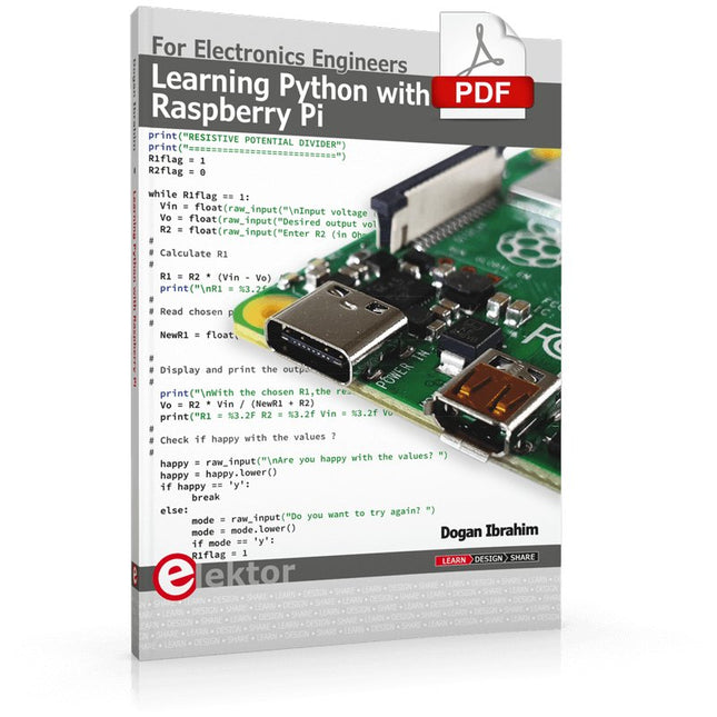
This book is about teaching the Python programming language using the Raspberry Pi 4 computer. The book makes an introduction to Raspberry Pi 4 and then teaches Python with the topics: variables, strings, arrays, matrices, tuples, lists, dictionaries, user functions, flow of control, printing, keyboard input, graphics, GUI, object oriented programming and many more topics.
The book is aimed for beginners, students, practising engineers, hobbyists, and for anyone else who may want to learn to program in Python.
The book includes many example programs and case studies. All the example programs and case studies have been tested fully by the author and are all working. The example programs aim to teach the various programming concepts of Python. The case studies cover the use of Python in the analysis and design of electronic circuits. Some of the case study topics are:
Resistor colour code identification
Resistive potential divider circuits
Resistive attenuator design
Zener diode voltage regulator design
RC and RLC transient circuits
Circuit frequency response
Saving data on external memory stick
Mesh and node circuit analysis using matrices
Resonance in RLC circuits
Transistor Biasing analysis
Transistor amplifier design
Design of active filters
Interfacing hardware with GPIO, I²C and SPI
Using Wi-Fi with Python and TCP/IP and UDP programs
Using Bluetooth from Python
Full program listings of all the programs used in the book are available at the Elektor website of the book. Readers should be able just to copy and use these programs in their Raspberry Pi projects without any modifications.
This book is intended as a highly-practical guide for Hobbyists, Engineers and Scientists wishing to build measurement and control systems to be controlled by a local or remote Personal Computer running the Linux operating system. Both hardware and software aspects of designing typical embedded systems are covered in detail with schematics, code listings and full descriptions. Numerous examples have been designed to show clearly how straightforward it can be to create the interfaces between digital and analog electronics, with programming techniques for creating control software for both local and remote systems. Hardware developers will appreciate the variety of circuits, including a novel, low cost modulated wireless link and will discover how using Matlab® overcomes the need for specialist programming skills.
Software developers will appreciate how a better understanding of circuits plus the freedom offered by Linux to directly control at the register level enables them to optimize related programs. There is no need to buy special equipment or expensive software tools in order to create embedded projects covered in this book. You can build such quality systems quickly using popular low-cost electronic components and free distributed or low-cost software tools. Some knowledge of basic electronics plus the very basics of C programming only is required.
Many projects in this book are developed using Matlab® being a very popular worldwide computational tool for research in engineering and science. The book provides a detailed description of how to combine the power of Matlab® with practical electronics.
With an emphasis on learning by doing, readers are encouraged by examples to program with ease; the book provides clear guidelines as to the appropriate programming techniques “on the fly”. Complete and well-documented source code is provided for all projects.
If you want to learn how to quickly build Linux-based applications able to collect, process and display data on a PC from various analog and digital sensors, how to control circuitry attached to a computer, then even how to pass data via a network or control your embedded system wirelessly and more – then this is the book for you!
Features of this Book
Use the power, flexibility and control offered only by a Linux operating system on a PC.
Use a free, distributed downloadable GNU C compiler Use (optional) a low-cost Student Version of Matlab®.
Use low-cost electronic sub-assemblies for projects.
Improve your skills in electronics, programming, networking and wireless design.
A full chapter is dedicated to controlling your sound card for audio input and output purposes.
Program sound using OSS and ALSA.
Learn how to combine electronic circuits, software, networks and wireless technologies in the complete embedded system.
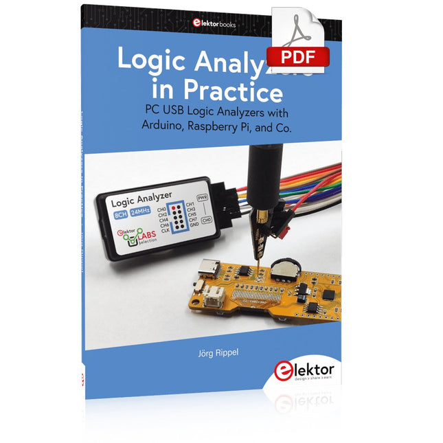
PC USB Logic Analyzers with Arduino, Raspberry Pi, and Co.
Step-by-step instructions guide you through the analysis of modern protocols such as I²C, SPI, UART, RS-232, NeoPixel, WS28xx, HD44780 and 1-Wire. With the help of numerous experimental circuits based on the Raspberry Pi Pico, Arduino Uno and the Bus Pirate, you will learn the practical application of popular USB logic analyzers.
All the experimental circuits presented in this book have been fully tested and are fully functional. The necessary program listings are included – no special programming or electronics knowledge is required for these circuits. The programming languages used are MicroPython and C along with the development environments Thonny and Arduino IDE.
This book uses several models of flexible and widely available USB logic analyzers and shows the strengths and weaknesses of each price range.
You will learn about the criteria that matter for your work and be able to find the right device for you.
Whether Arduino, Raspberry Pi or Raspberry Pi Pico, the example circuits shown allow you to get started quickly with protocol analysis and can also serve as a basis for your own experiments.
After reading this book, you will be familiar with all the important terms and contexts, conduct your own experiments, analyze protocols independently, culminating in a comprehensive knowledge set of digital signals and protocols.
Double Backlit User Interface: The dual backlit button is just like the single backlit button, but twice the fun! Use this component when you need to operate something up and down, or right to left. Using cut-out vinyl, you can create icons and stickers on fabric that show your users button functionality.
Features
Component: 4.6 x 6.3"
Individual Button Size: 1" radius circle
Press Durability: Up to 10,000 presses under 5lbf
LED Voltage: 5 V
The single backlit button is a simple mechanical switch that comes with an LED inside. When you press the button, the circuit is completed, driving your pin high or low. Use the embedded LED to make a glowing power icon, logo , or whatever suits your fancy.
Features
Press durability: Up to 10,000 times pressing under 5lbf (22.24 N)
LED Voltage: 5 V
Component: 2" x 3" Individual (5,08 x 7,62 cm)
Button Size: 1" radius circle (2,54 cm)
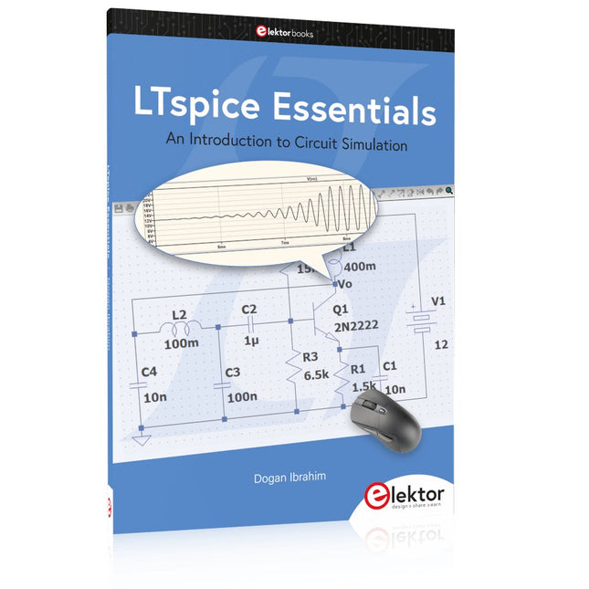
An Introduction to Circuit Simulation
LTspice, developed by Analog Devices, is a powerful, fast, and free SPICE simulator, schematic capture, and waveform viewer with a large database of components supported by SPICE models from all over the world. Drawing a schematic in LTspice is easy and fast. Thanks to its powerful graphing features, you can visualize the voltages and currents in a circuit, and also the power consumption of its components and much more.
This book is about learning to design and simulate electronic circuits using LTspice. Among others, the following topics are treated:
DC and AC circuits
Signal diodes and Zener diodes
Transistor circuits including oscillators
Thyristor/SCR, diac, and triac circuits
Operational amplifier circuits including oscillators
The 555 timer IC
Filters
Voltage regulators
Optocouplers
Waveform generation
Digital logic simulation including the 74HC family
SPICE modeling LTspice is a powerful electronic circuit simulation tool with many features and possibilities. Covering them all in detail is not possible in a book of this size. Therefore, this book presents the most common topics like DC and AC circuit analysis, parameter sweeping, transfer functions, oscillators, graphing, etc. Although this book is an introduction to LTspice, it covers most topics of interest to people engaged in electronic circuit simulation.
The book is aimed at electronic/electrical engineers, students, teachers, and hobbyists. Many tested simulation examples are given in the book. Readers do not need to have any computer programming skills, but it will help if they are familiar with basic electronic circuit design and operation principles. Readers who want to dive deeper can find many detailed tutorials, articles, videos, design files, and SPICE circuit models on the Internet.
All the simulation examples used in the book are available as files at the webpage of this book. Readers can use these example circuits for learning or modify them for their own applications.
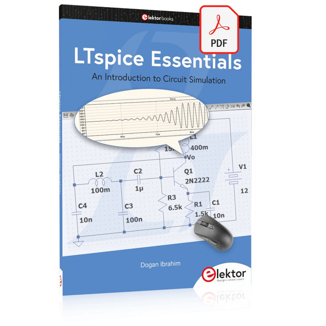
LuckFox Pico Mini is a compact Linux micro development board based on the Rockchip RV1103 chip, providing a simple and efficient development platform for developers. It supports a variety of interfaces, including MIPI CSI, GPIO, UART, SPI, I²C, USB, etc., which is convenient for quick development and debugging.
Features
Single-core ARM Cortex-A7 32-bit core with integrated NEON and FPU
Built-in Rockchip self-developed 4th generation NPU, features high computing precision and supports int, int8, and int16 hybrid quantization. The computing power of int8 is 0.5 TOPS, and up to 1.0 TOPS with int4
Built-in self-developed third-generation ISP3.2, supports 4-Megapixel, with multiple image enhancement and correction algorithms such as HDR, WDR, multi-level noise reduction, etc.
Features powerful encoding performance, supports intelligent encoding mode and adaptive stream saving according to the scene, saves more than 50% bit rate of the conventional CBR mode so that the images from camera are high-definition with smaller size, double the storage space
Built-in RISC-V MCU supports low power consumption and fast start-up, supports 250 ms fast picture capture and loading Al model library at the same time to realize face recognition "in one second"
Built-in 16-bit DRAM DDR2, which is capable of sustaining demanding memory bandwidths
Integrated with built-in POR, audio codec and MAC PHY
Specifications
Processor
ARM Cortex-A7, single-core 32-bit CPU, 1.2 GHz, with NEON and FPU
NPU
Rockchip 4th-gen NPU, supports int4, int8, int16; up to 1.0 TOPS (int4)
ISP
Third-gen ISP3.2, up to 4 MP input at 30fps, HDR, WDR, noise reduction
RAM
64 MB DDR2
Storage
128 MB SPI NAND Flash
USB
USB 2.0 Host/Device via Type-C
Camera Interface
MIPI CSI 2-lane
GPIO Pins
17 GPIO pins
Power Consumption
Low power, RISC-V MCU for fast startup
Dimensions
28 x 21 mm
Downloads
Wiki
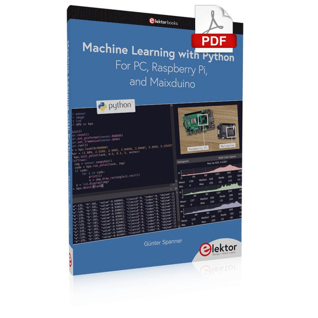
Most people are increasingly confronted with the applications of Artificial Intelligence (AI). Music or video ratings, navigation systems, shopping advice, etc. are based on methods that can be attributed to this field.
The term Artificial Intelligence was coined in 1956 at an international conference known as the Dartmouth Summer Research Project. One basic approach was to model the functioning of the human brain and to construct advanced computer systems based on this. Soon it should be clear how the human mind works. Transferring it to a machine was considered only a small step. This notion proved to be a bit too optimistic. Nevertheless, the progress of modern AI, or rather its subspecialty called Machine Learning (ML), can no longer be denied.
In this book, several different systems will be used to get to know the methods of machine learning in more detail. In addition to the PC, both the Raspberry Pi and the Maixduino will demonstrate their capabilities in the individual projects. In addition to applications such as object and facial recognition, practical systems such as bottle detectors, person counters, or a “talking eye” will also be created.
The latter is capable of acoustically describing objects or faces that are detected automatically. For example, if a vehicle is in the field of view of the connected camera, the information 'I see a car!' is output via electronically generated speech. Such devices are highly interesting examples of how, for example, blind or severely visually impaired people can also benefit from AI systems.
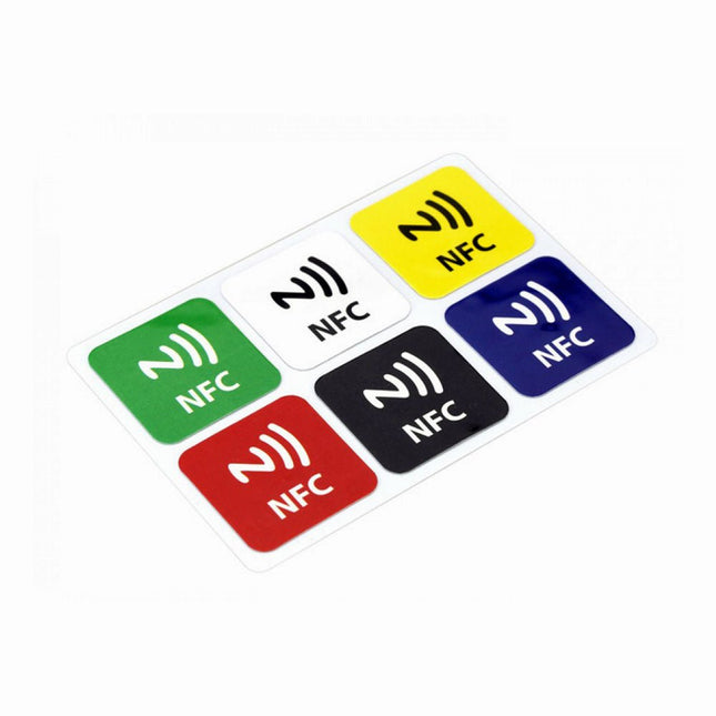
Features NFC chip material: PET + Etching antenna Chip: NTAG216 (compatible with all NFC phones) Frequency: 13.56 MHz (High Frequency) Reading time: 1 - 2 ms Storage capacity: 888 bytes Read and write times: > 100,000 times Reading distance: 0 - 5 mm Data retention: > 10 years NFC chip size: Diameter 30 mm Non-contact, no friction, the failure rate is small, low maintenance costs Read rate, verification speed, which can effectively save time and improve efficiency Waterproof, dustproof, anti-vibration No power comes with an antenna, embedded encryption control logic, and communication logic circuit Included 1x NFC Stickers (6-color kit)
For Speed, Area, Power, and Reliability
This book teaches the fundamentals of FPGA operation, covering basic CMOS transistor theory to designing digital FPGA chips using LUTs, flip-flops, and embedded memories. Ideal for electrical engineers aiming to design large digital chips using FPGA technology.
Discover:
The inner workings of FPGA architecture and functionality.
Hardware Description Languages (HDL) like Verilog and VHDL.
The EDA tool flow for converting HDL source into a functional FPGA chip design.
Insider tips for reliable, low power, and high performance FPGA designs.
Example designs include:
Computer-to-FPGA UART serial communication.
An open-source Sump3 logic analyzer implementation.
A fully functional graphics controller.
What you need:
Digilent BASYS3 or similar FPGA eval board with an AMD/Xilinx FPGA.
Vivado EDA tool suite (available for download from AMD website free of charge).
Project source files available from author’s GitHub site.
Third, extended and revised edition with AVR Playground and Elektor Uno R4
Arduino boards have become hugely successful. They are simple to use and inexpensive. This book will not only familiarize you with the world of Arduino but it will also teach you how to program microcontrollers in general. In this book theory is put into practice on an Arduino board using the Arduino programming environment.
Some hardware is developed too: a multi-purpose shield to build some of the experiments from the first 10 chapters on; the AVR Playground, a real Arduino-based microcontroller development board for comfortable application development, and the Elektor Uno R4, an Arduino Uno R3 on steroids.
The author, an Elektor Expert, provides the reader with the basic theoretical knowledge necessary to program any microcontroller: inputs and outputs (analog and digital), interrupts, communication busses (RS-232, SPI, I²C, 1-wire, SMBus, etc.), timers, and much more. The programs and sketches presented in the book show how to use various common electronic components: matrix keyboards, displays (LED, alphanumeric and graphic color LCD), motors, sensors (temperature, pressure, humidity, sound, light, and infrared), rotary encoders, piezo buzzers, pushbuttons, relays, etc. This book will be your first book about microcontrollers with a happy ending!
This book is for you if you are a beginner in microcontrollers, an Arduino user (hobbyist, tinkerer, artist, etc.) wishing to deepen your knowledge,an Electronics Graduate under Undergraduate student or a teacher looking for ideas.
Thanks to Arduino the implementation of the presented concepts is simple and fun. Some of the proposed projects are very original:
Money Game
Misophone (a musical fork)
Car GPS Scrambler
Weather Station
DCF77 Decoder
Illegal Time Transmitter
Infrared Remote Manipulator
Annoying Sound Generator
Italian Horn Alarm
Overheating Detector
PID Controller
Data Logger
SVG File Oscilloscope
6-Channel Voltmeter
All projects and code examples in this book have been tried and tested on an Arduino Uno board. They should also work with the Arduino Mega and every other compatible board that exposes the Arduino shield extension connectors.
Please note
For this book, the author has designed a versatile printed circuit board that can be stacked on an Arduino board. The assembly can be used not only to try out many of the projects presented in this book but also allows for new exercises that in turn provide the opportunity to discover new techniques. Also available is a kit of parts including the PCB and all components. With this kit you can build most of the circuits described in the book and more.
Datasheets Active Components Used (.PDF file):
ATmega328 (Arduino Uno)
ATmega2560 (Arduino Mega 2560)
BC547 (bipolar transistor, chapters 7, 8, 9)
BD139 (bipolar power transistor, chapter 10)
BS170 (N-MOS transistor, chapter 8)
DCF77 (receiver module, chapter 9)
DS18B20 (temperature sensor, chapter 10)
DS18S20 (temperature sensor, chapter 10)
HP03S (pressure sensor, chapter 8)
IRF630 (N-MOS power transistor, chapter 7)
IRF9630 (P-MOS power transistor, chapter 7)
LMC6464 (quad op-amp, chapter 7)
MLX90614 (infrared sensor, chapter 10)
SHT11 (humidity sensor, chapter 8)
TS922 (dual op-amp, chapter 9)
TSOP34836 (infrared receiver, chapter 9)
TSOP1736 (infrared receiver, chapter 9)
MPX4115 (analogue pressure sensor, chapter 11)
MCCOG21605B6W-SPTLYI (I²C LCD, chapter 12)
SST25VF016B (SPI EEPROM, chapter 13)
About the author
Clemens Valens, born in the Netherlands, lives in France since 1997. Manager at Elektor Labs and Webmaster of ElektorLabs, in love with electronics, he develops microcontroller systems for fun, and sometimes for his employer too. Polyglot—he is fluent in C, C++, PASCAL, BASIC and several assembler dialects—Clemens spends most of his time on his computer while his wife, their two children and two cats try to attract his attention (only the cats succeed). Visit the author’s website: www.polyvalens.com.Authentic testimony of Hervé M., one of the first readers of the book:'I almost cried with joy when this book made me understand things in only three sentences that seemed previously completely impenetrable.'
Mastering Surface Mount Technology takes you on a crash course in techniques, tips and know-how to successfully introduce surface mount technology in your workflow. Even if you are on a budget you too can jumpstart your designs with advanced fine pitch parts.
Besides explaining methodology and equipment, attention is given to SMT parts technologies and soldering methods. In a step by step way, several projects introduce you to handling surface mount parts and the required skills to successfully build SMT assemblies. Many practical tips and tricks are disclosed that bring surface mount technology into everyone's reach without breaking the bank.
Programming and Projects for the Minima and WiFi
Based on the low-cost 8-bit ATmega328P processor, the Arduino Uno R3 board is likely to score as the most popular Arduino family member, and this workhorse has been with us for many years. Eleven years later, the long-overdue successor, the Arduino Uno R4, was released. It is built around a 48 MHz, 32-bit Arm Cortex-M4 microcontroller and provides significantly expanded SRAM and Flash memory. Additionally, a higher-precision ADC and a new DAC are added to the design. The Uno R4 board also supports the CAN Bus with an interface.
Two versions of the board are available: Uno R4 Minima, and Uno R4 WiFi. This book is about using these new boards to develop many different and interesting projects with just a handful of parts and external modules. All projects described in the book have been fully tested on the Uno R4 Minima or the Uno R4 WiFi board, as appropriate.
The project topics include the reading, control, and driving of many components and modules in the kit as well as on the relevant Uno R4 board, including
LEDs
7-segment displays (using timer interrupts)
LCDs
Sensors
RFID Reader
4x4 Keypad
Real-time clock (RTC)
Joystick
8×8 LED matrix
Motors
DAC (Digital-to-analog converter)
LED matrix
WiFi connectivity
Serial UART
CAN bus
Infrared controller and receiver
Simulators
… all in creative and educational ways with the project operation and associated software explained in great detail.
Mastering the I²C Bus takes you on an exploratory journey of the I²C Bus and its applications. Besides the Bus protocol, plenty of attention is given to the practical applications and designing a stable system. The most common I²C compatible chip classes are covered in detail.
Two experimentation boards are available that allow for rapid prototype development. These boards are completed by a USB to I²C probe and a software framework to control I²C devices from your computer. All samples programs can be downloaded from the 'Attachments/Downloads' section on this page.
Projects built on Board 1:
USB to I²C Interface, PCA 9534 Protected Input, PCA 9534 Protected Output, PCA 9553 PWM LED Controller, 24xxx EEPROM Module, LM75 Temperature Sensor, PCA8563 Real-time Clock with Battery Backup, LCD and Keyboard Module, Bus Power Supply.
Projects built on Board 2:
Protected Input, Protected Output, LM75 Temperature Sensor, PCF8574 I/O Board, SAA1064 LED Display, PCA9544 Bus Expander, MCP40D17 Potentiometer, PCF8591 AD/DA, ADC121 A/D Converter, MCP4725 D/A Converter, 24xxx EEPROM Module.
Kick off to FPGA Programming with the MAX1000 Board and VHDPlus
Ready to master FPGA programming? With this bundle, you'll dive into the world of Field-Programmable Gate Arrays (FPGAs) – a configurable integrated circuit that can be programmed after manufacturing. Bring your ideas to life, from simple projects to complete microcontroller systems!
The MAX1000 is a compact and powerful FPGA development board packed with features like memory, user LEDs, push-buttons, and flexible I/O ports. It’s the ideal starting point for anyone wanting to learn about FPGAs and Hardware Description Languages (HDLs).
With the enclosed book "FPGA Programming and Hardware Essentials" you'll get hands-on with the VHDPlus programming language – a simpler version of VHDL. You'll work on practical projects using the MAX1000, helping you gain the skills and confidence to unleash your creativity.
Projects in the Book
Arduino-driven BCD to 7-Segment Display Decoder
Use an Arduino Uno R4 to supply BCD data to the decoder, counting from 0 to 9 with a one-second delay
Multiplexed 4-Digit Event Counter
Create an event counter that displays the total count on a 4-digit display, incrementing with each button press
PWM Waveform with Fixed Duty Cycle
Generate a PWM waveform at 1 kHz with a fixed duty cycle of 50%
Ultrasonic Distance Measurement
Measure distances using an ultrasonic sensor, displaying the results on a 4-digit 7-segment LED
Electronic Lock
Build a simple electronic lock using combinational logic gates with push buttons and an LED output
Temperature Sensor
Monitor ambient temperature with a TMP36 sensor and display the readings on a 7-segment LED
MAX1000 FPGA Development Board
The MAX1000 is a customizable IoT/Maker Board ready for evaluation, development and/or use in a product. It is built around the Intel MAX10 FPGA, which is the industry’s first single chip, non-volatile programmable logic device (PLDs) to integrate the optimal set of system components.
Users can now leverage the power of tremendous re-configurability paired with a high-performance, low-power FPGA system. Providing internally stored dual images with self-configuration, comprehensive design protection features, integrated ADCs and hardware to implement the Nios II 32-bit microcontroller IP, MAX10 devices are ideal solution for system management, protocol bridging, communication control planes, industrial, automotive and consumer applications.
The MAX1000 is equipped with an Arrow USB Programmer2, SDRAM, flash memory, accelerometer sensor and PMOD/Arduino MKR connectors making it a fully featured plug and play solution without any additional costs.
Specifications
MAX 10
8 kLE
- Flash
Dual inside
- ADC
8x 12 Bit
- Temperature Range
0~85°C
- Supply
USB/pins
SDRAM
8 MB
3-axis MEMS
LIS3DH
USB Programmer
on board
MEMS Oscillator
12 MHz
Switch/LED
2x / 8x
Contents of the Bundle
Book: FPGA Programming and Hardware Essentials (normal price: €40)
MAX1000 FPGA Development Board (normal price: €45)
Downloads
Software
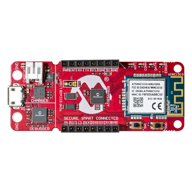
The AVR-IoT WA development board combines a powerful ATmega4808 AVR MCU, an ATECC608A CryptoAuthentication secure element IC and the fully certified ATWINC1510 Wi-Fi network controller – which provides the most simple and effective way to connect your embedded application to Amazon Web Services (AWS). The board also includes an on-board debugger, and requires no external hardware to program and debug the MCU.
Out of the box, the MCU comes preloaded with a firmware image that enables you to quickly connect and send data to the AWS platform using the on-board temperature and light sensors. Once you are ready to build your own custom design, you can easily generate code using the free software libraries in Atmel START or MPLAB Code Configurator (MCC).
The AVR-IoT WA board is supported by two award-winning Integrated Development Environments (IDEs) – Atmel Studio and Microchip MPLAB X IDE – giving you the freedom to innovate with your environment of choice.
Features
ATmega4808 microcontroller
Four user LED’s
Two mechanical buttons
mikroBUS header footprint
TEMT6000 Light sensor
MCP9808 Temperature sensor
ATECC608A CryptoAuthentication™ device
WINC1510 WiFi Module
On-board Debugger
Auto-ID for board identification in Atmel Studio and Microchip MPLAB X
One green board power and status LED
Programming and debugging
Virtual COM port (CDC)
Two DGI GPIO lines
USB and battery powered
Integrated Li-Ion/LiPo battery charger
Microcontrollers have become an indispensable part of modern electronics. They make things possible that vastly exceed what could be done previously. Innumerable applications show that almost nothing is impossible.
There’s thus every reason to learn more about them, but that raises the question of where to find a good introduction to this fascinating technology. The answer is easy: this Microcontroller Basics book, combined with the 89S8252 Flash Board project published by Elektor Electronics.
However, this book offers more than just a basic introduction. It clearly explains the technology using various microcontroller circuits and programs written in several different programming languages. Three microcontrollers from the 8051 family are used in the sample applications, ranging from the simple 89C2051 to the AN2131, which is designed to support USB applications. The programming tools include assemblers, Basic-52 and BASCOM-51, and several C compilers. Every reader can thus find the programming environment most suitable to his or her needs.
In the course of the book, the reader gradually develops increased competence in converting his or her ideas into microcontroller circuitry. All of the sample programs can be downloaded from the Elektor Electronics website or the author’s website. That has the added advantage that the latest versions are always available.