The Pro Tech Toolkit is the one thing every DIYer, fixer, hacker, hobbyist, and professional needs to tackle any job.
Every tool in the Pro Tech Toolkit has been re-engineered to be better. From the 64 Bit Driver Kit to the iFixit Opening Picks, every tool is specially designed and selected to maximize your repair capabilities.
At the core of this kit is the iFixit 64 Bit Driver Kit, designed with extensive research into what fastener types are currently used in the consumer electronics industry and which legacy fasteners are still in demand by consumers. From the Apple Watch with its new tiny Tri-Point screws to vintage Nintendo game consoles with gamebit fasteners, the 64 bit kit covers them all with the highest quality CNC machined bits. Even the sturdy case was carefully engineered, having no hinges or latches to break, and features a sorting tray inside the magnetically attached lid.
High-Performance Toolkit for DIY Repairs
The perfect toolkit for pros to average joes.
Contains all the poking, prying, gripping, lifting, ESD safety, and screw driving tools needed to service consumer electronics.
Completely re-engineered to provide all the tools that you need, and none that you don't.
Included
Anti-Static Wrist Strap – protection for circuits against static electricity
Small Suction Handle – suction handle for holding onto things lacking handles
3x iFixit Opening Tool – soft plastic prying tools
6x iFixit Opening Picks – thin prying tool for opening electronic devices
Nylon Tipped Reverse Tweezers – to elevate and hold your work
Angled ESD Tweezers – ESD-safe, feature teeth for tougher grip
Blunt ESD Tweezers – ESD-safe, feature teeth for tougher grip
Standard Spudger – tough antistatic tool for a variety of purposes
Halberd Spudger – features a hook for scooping, scraping, pulling, and guiding.ESD-safe.
Metal Spudger – for more powerful prying, scraping, probing, and poking action
Jimmy – handy tool for 'Jimmy'ing open electronics.
Magnetic Pad – Holds tiny screws and parts during repairs
Tool Roll – Durable and compact
Mako Precision Bit Set – all the bits needed for repairs on small electronics
Mako Precision Bit Set Includes
64 Bit Driver
150 mm Flex Extension
4 mm Screwdriver Bits
Phillips – 000, 00, 0, 1, 2
Flathead – 1, 1.5, 2, 2.5, 3, 4 mm
Torx – T2, T3, T4, T5
Torx Security – TR6, TR7, TR8, TR9, TR10, TR15, TR20, TR25
Pentalobe – P2, P5, P6
JIS – J000, J00, J0, J1
Hex – 0.7, 0.9, 1.3, 1.5, 2, 2.5, 3, 3.5, 4, 4.5, 5 mm
Tri-point – Y000, Y00, Y0, Y1
Nut Driver – 2.5, 3, 3.5, 4, 4.5, 5, 5.5 mm
Square – 1, 2
Gamebit – 3.8, 4.5 mm
Spanner – 6, 8
Triangle – 2, 3 mm
Standoff Bit for iPhone
Oval Bit
Magnetic Pickup Bit
SIM Eject Bit
1/4" to 4 mm Driver Adapter
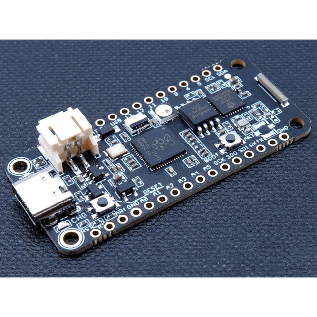
The Challenger RP2040 NFC is a small embedded computer, equipped with an advanced on-board NFC controller (NXP PN7150), in the popular Adafruit Feather form factor. It is based on an RP2040 microcontroller chip from the Raspberry Pi Foundation which is a dual-core Cortex-M0 that can run on a clock up to 133 MHz.
NFC
The PN7150 is a full featured NFC controller solution with integrated firmware and NCI interface designed for contactless communication at 13.56 MHz. It is fully compatible with NFC forum requirements and is greatly designed based on learnings from previous NXP NFC device generation. It is the ideal solution for rapidly integrating NFC technology in any application, especially small embedded systems reducing Bill of Material (BOM).
The integrated design with full NFC forum compliancy gives the user all the following features:
Embedded NFC firmware providing all NFC protocols as pre-integrated feature.
Direct connection to the main host or microcontroller, by I²C-bus physical and NCI protocol.
Ultra-low power consumption in polling loop mode.
Highly efficient integrated power management unit (PMU) allowing direct supply from a battery.
Specifications
Microcontroller
RP2040 from Raspberry Pi (133 MHz dual-core Cortex-M0)
SPI
One SPI channels configured
I²C
Two I²C channel configured (dedicated I²C for the PN7150)
UART
One UART channel configured
Analog inputs
4 analog input channels
NFC module
PN7150 from NXP
Flash memory
8 MB, 133 MHz
SRAM memory
264 KB (divided into 6 banks)
USB 2.0 controller
Up to 12 MBit/s full speed (integrated USB 1.1 PHY)
JST Battery connector
2.0 mm pitch
On board LiPo charger
450 mA standard charge current
Dimensions
51 x 23 x 3,2 mm
Weight
9 g
Note: Antenna is not included.
Downloads
Datasheet
Quick start example
The Challenger RP2040 WiFi is a small embedded computer equipped with a WiFi module, in the popular Adafruit Feather form factor. It is based on an RP2040 microcontroller chip from the Raspberry Pi Foundation which is a dual-core Cortex-M0 that can run on a clock up to 133 MHz.
The RP2040 is paired with a 8 MB high-speed flash capable of supplying data up to the max speed. The flash memory can be used both to store instructions for the microcontroller as well as data in a file system and having a file system available makes it easy to store data in a structured and easy to program approach.
The device can be powered from a Lithium Polymer battery connected through a standard 2.0 mm connector on the side of the board. An internal battery charging circuit allows you to charge your battery safely and quickly. The device is shipped with a programming resistor that sets the charging current to 250 mA. This resistor can be exchanged by the user to either increase or decrease the charging current, depending on the battery that is being used.
The WiFi section on this board is based on the Espressif ESP8285 chip which basically is a ESP8266 with 1 MB flash memory integrated onto the chip making it a complete WiFi only requiring very few external components.
The ESP8285 is connected to the microcontroller using a UART channel and the operation is controlled using a set of standardized AT-commands.
Specifications
Microcontroller
RP2040 from Raspberry Pi (133 MHz dual-core Cortex-M0)
SPI
One SPI channel configured
I²C
One I²C channel configured
UART
One UART channel configured (second UART is for the WiFi chip)
Analog inputs
4 analog input channels
WLAN controller
ESP8285 from Espressif (160 MHz single-core Tensilica L106)
Flash memory
8 MByte, 133 MHz
SRAM memory
264 KByte (divided into 6 banks)
USB 2.0 controller
Up to 12 MBit/s full speed (integrated USB 1.1 PHY)
JST Battery connector
2.0 mm pitch
Onboard LiPo charger
250 mA standard charge current
Onboard NeoPixel LED
RGB LED
Dimensions
51 x 23 x 3,2 mm
Weight
9 g
Downloads
Datasheet
Design files
Product errata
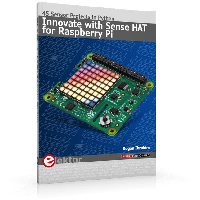
Ready to explore the world around you? By attaching the Sense HAT to your Raspberry Pi, you can quickly and easily develop a variety of creative applications, useful experiments, and exciting games.
The Sense HAT contains several helpful environmental sensors: temperature, humidity, pressure, accelerometer, magnetometer, and gyroscope. Additionally, an 8x8 LED matrix is provided with RGB LEDs, which can be used to display multi-color scrolling or fixed information, such as the sensor data. Use the small onboard joystick for games or applications that require user input. In Innovate with Sense HAT for Raspberry Pi, Dr. Dogan Ibrahim explains how to use the Sense HAT in Raspberry Pi Zero W-based projects. Using simple terms, he details how to incorporate the Sense HAT board in interesting visual and sensor-based projects. You can complete all the projects with other Raspberry Pi models without any modifications.
Exploring with Sense HAT for Raspberry Pi includes projects featuring external hardware components in addition to the Sense HAT board. You will learn to connect the Sense HAT board to the Raspberry Pi using jumper wires so that some of the GPIO ports are free to be interfaced to external components, such as to buzzers, relays, LEDs, LCDs, motors, and other sensors.
The book includes full program listings and detailed project descriptions. Complete circuit diagrams of the projects using external components are given where necessary. All the projects were developed using the latest version of the Python 3 programming language. You can easily download projects from the book’s web page. Let’s start exploring with Sense HAT.
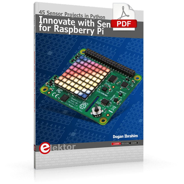
An Introduction to RISC-V
RISC-V is an Instruction Set Architecture (ISA) that is both free and open. This means that the RISC-V ISA itself does not require a licensing fee, although individual implementations may do so. The RISC-V ISA is curated by a non-profit foundation with no commercial interest in products or services that use it, and it is possible for anyone to submit contributions to the RISC-V specifications. The RISC-V ISA is suitable for applications ranging from embedded microcontrollers to supercomputers.
This book will first describe the 32-bit RISC-V ISA, including both the base instruction set as well as the majority of the currently-defined extensions. The book will then describe, in detail, an open-source implementation of the ISA that is intended for embedded control applications. This implementation includes the base instruction set as well as a number of standard extensions.
After the description of the CPU design is complete the design is expanded to include memory and some simple I/O. The resulting microcontroller will then be implemented in an affordable FPGA development board (available from Elektor) along with a simple software application so that the reader can investigate the finished design.
The Internet of Things (IoT) is a new concept in intelligent automation and intelligent monitoring using the Internet as the communications medium. The “Things” in IoT usually refer to devices that have unique identifiers and are connected to the Internet to exchange information with each other. Such devices usually have sensors and/or actuators that can be used to collect data about their environments and to monitor and control their environments. The collected data can be processed locally or it can be sent to centralized servers or to the cloud for remote storage and processing. For example, a small device at the size of a matchbox can be used to collect data about the temperature, relative humidity and the atmospheric pressure. This data can be sent and stored in the cloud. Anyone with a mobile device can then access and monitor this data at any time and from anywhere on Earth provided there is Internet connectivity. In addition, users can for example, adjust the central heating remotely using their mobile devices and accessing the cloud.
This book is written for students, for practising engineers and for hobbyists who want to learn more about the building blocks of an IoT system and also learn how to setup an IoT system using these blocks.
Chapter 1 is an introduction to the IoT systems. In Chapter 2, the basic concepts and possible IoT architectures are discussed. The important parts of any IoT system are the sensors and actuators and they are described briefly in Chapter 3. The devices in an IoT system usually communicate with each other and the important aspect of IoT communication is covered in Chapter 4. Chapter 5 proceeds with the features of some of the commonly used development kits. One of these, the Clicker 2 for PIC18FJ manufactured by mikroElektronika, can be used as a processor in IoT systems and its features are described in detail in Chapter 6. A popular microcontroller C language, mikroC Pro for PIC gets introduced in Chapter 7. Chapter 8 covers the use of a click board with the Clicker 2 for PIC18FJ development kit. Similarly, the use of a sensor click board is described as a project in Chapter 9, and an actuator board in Chapter 10. Chapters 11 and 12 cover Bluetooth and Wi-Fi technologies in microcontroller based systems, and the remaining chapters of the book demo the creation of a simple Wi-Fi based IoT system with cloud-based data storage.
This book has been written with the assumption that the reader has taken a course on digital logic design and has been exposed to writing programs using at least one high-level programming language. Knowledge of the C programming language will be very useful. Also, familiarity with at least one member of the PIC series of microcontrollers (e.g. PIC16 or PIC18) will be an advantage. The knowledge of assembly language programming is not required because all the projects in the book are based on using the C language. If you are a total beginner in programming you can still access the e-book, but first you are advised to study introductory books on microcontrollers.
This book is aimed at practising engineers, students and hobbyists. It is intended as a source of reference for hardware and software associated with instrumentation and control engineering. Examples are presented from a range of industries and applications.
Throughout the book, circuit diagrams and software listings are described, typical of many measurement and control applications. The hardware and software designs may be used as a basis for application by the reader.
The book contains examples of PIC, PLC, PAC and PC programming. All code samples are available to download free of charge from the support website.
After an introductory section on control theory and modelling, the text focus is upon software for control system simulation and implementation, with appropriate reference to interfacing, electronic hardware and computing platforms.
Introduction to Control Engineering is a sourcebook of solutions for control system applications!
Learn RC and RL Filters with Hands-On Circuits and Simulation
Introduction to Electronic Filters is your comprehensive guide to understanding, designing, and applying first-order electronic filters using resistors, capacitors, and inductors. Whether you are a student, maker, or educator, this book demystifies the theory behind RC and RL filters and bridges the gap between concepts and real-world applications through simulation and experimentation.
From the basics of frequency response and phase shift to hands-on breadboard builds and Python-based simulations, this book offers a deeply practical learning experience. You will learn to analyse filters using Bode plots and phasors, and explore applications in audio tone shaping, sensor signal conditioning, noise reduction, and power supply filtering.
As you progress, you’ll build, measure, simulate, and tune filters using modern tools like CircuitLab, Python, and the Analog Discovery 3. Each chapter includes thoughtfully crafted activities that reinforce learning by doing – designing filters for specific tasks, simulating dynamic behaviour, and observing how theory translates into performance.
Inside you’ll find:
A clear introduction to the fundamentals of electronic filters
Detailed explanations of RC and RL filters, cutoff frequency, and phase
Guided activities using both simulation and hardware tools
Real-life applications in audio, sensors, power supplies, and more
A beginner-friendly primer on Python and algebra for electronics
Whether you’re working through simulations or experimenting with real components on your workbench, this book will help you develop a solid understanding of electronic filters and their role in practical circuits.
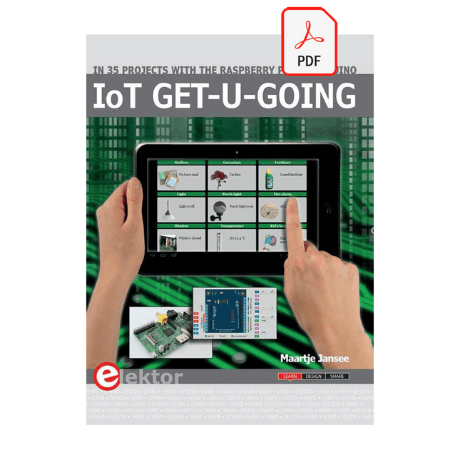
In 35 Projects with the Raspberry Pi and Arduino
The Internet of Things (IoT) is a trend with a strong technological impulse. At home, we want to do everything on our tablets, from browsing Facebook to watching TV, from operating lights to keeping an eye on the temperature.
In 35 fun projects, this book will show you how to build your own Internet of Things system. We'll cover the hardware (primarily the Raspberry Pi and Arduino) and the software that makes control via Internet possible. We employ Wi-Fi and radio links so no requirement any longer to install cabling crisscross through your home.
Assuming the projects in the book are finished, you have a complete Internet of Things system that allows you to control and view of everything in your home. For example, if there's something in the mail box or the car is securely in the garage. Also, you can switch on the lights and the alarm from your couch. The crisp explanations allow the projects to be customized with ease, for example, to turn on your coffee machine or TV remotely. The index gives easy access to creative projects that can serve as an example, enabling you to do all the connecting to the IoT independently. All project software can be downloaded free of charge from the Elektor website.
In this unique book, Raspberry Pi, Arduino and HTML webpages with stylesheets and JavaScript come together in clearly-described, easy-to-build projects. This special book is an essential part of your collection!
There are many so-called 'Arduino compatible' platforms on the market. The ESP8266 – in the form of the WeMos D1 Mini Pro – is one that really stands out. This device includes WiFi Internet access and the option of a flash file system using up to 16 MB of external flash memory. Furthermore, there are ample in/output pins (though only one analogue input), PWM, I²C, and one-wire. Needless to say, you are easily able to construct many small IoT devices!
This book contains the following builds:
A colourful smart home accessory
refrigerator controller
230 V power monitor
door lock monitor
and some further spin-off devices.
All builds are documented together with relevant background information for further study. For your convenience, there is a small PCB for most of the designs; you can also use a perf board. You don’t need to be an expert but the minimum recommended essentials include basic experience with a PC, software, and hardware, including the ability to surf the Internet and assemble PCBs.
And of course: A handle was kept on development costs. All custom software for the IoT devices and PCB layouts are available for free download from at Elektor.com.
TapNLink modules provide wireless interfaces for linking electronic systems to mobile devices and the Cloud. TapNLink connects directly to the target system's microcontroller. It integrates into and is powered by the target system. All TapNLink products are easily configured to control access by different types of users to data in the target system.
TapNLink facilitates rapid creation of Human Machine Interfaces (HMI) that run on Android, iOS and Windows mobiles. HMI apps are easily customized for different users and can be deployed and updated to keep pace with evolving system requirements and user needs.
TapNLink Wi-Fi modules can also be configured to connect the target system permanently to a wireless network and the Cloud. This enables permanent logging of target system data and alarms.
Features
Wireless Channels
Wi-Fi 802.11b/g/n
Bluetooth Low Energy (BLE 4.2)
Near Field Communication (NFC) Type5 tag (ISO/IEC 15693)
Supported Target Connections: Connects on 2 GPIO of the target microcontroller and supports:
Serial interface with Software Secure Serial Port (S3P) protocol
Serial interface with ARM SWD debug protocol.
UART with Modbus protocol
Mobile Platform Support
HTML5 web apps (Android, iOS)
API for Cordova (Android, iOS, Windows 10)
Java (Android, iOS native)
Auto-app generator for Android and iOS mobiles
Security
Configurable access profiles
Configurable, encrypted passwords
AES-128/256 module-level data encryption
Configurable secure pairing with NFC
Dimensions: 38 mm x 28 mm x 3 mm
Electrical Characteristics
Input voltage: 2.3V to 3.6 V
Low power consumption:
Standby: 100 µA
NFC Tx/Rx: 7 mA
Wi-Fi Rx: 110 mA
Wi-Fi Tx : 280 mA (802.11b)
Temperature Range: -20°C ~ +55°C
Compliance
CE (Europe), FCC (USA), IC (Canada)
REACH
RoHS
WEEE
Ordering Information
Base Part Number: TnL-FIW103
MOQ: 20 modules
TapNLink modules pre-qualified, pre-programmed and ready to configure.
IoTize Studio configuration and testing software
Software for HMI on mobile devices (iOS, Android, Windows 10)
IoTize Cloud MQTT infrastructure (open source)
For more information, check out the datasheet here.
The JOY-iT Armor Case BLOCK is a robust aluminum enclosure designed specifically for the Raspberry Pi 5. It offers excellent protection against heat and physical shocks, making it suitable for challenging environments. Its compact design ensures that it doesn't require additional space, allowing for seamless integration into existing projects.
The case includes a large heatsink to enhance cooling efficiency. Installation is straightforward, with four screws (included) securing the case to the Raspberry Pi.
Specifications
Material
CNC milled aluminum alloy
Cooling performance
Idle: ~39°CFull load: ~75°C
Special features
Large heat sink, protection against shocks and heat with the same volume as without housing
Dimensions (top side)
69 x 56 x 15,5 mm
Dimensions (bottom side)
87 x 56 x 7,5 mm
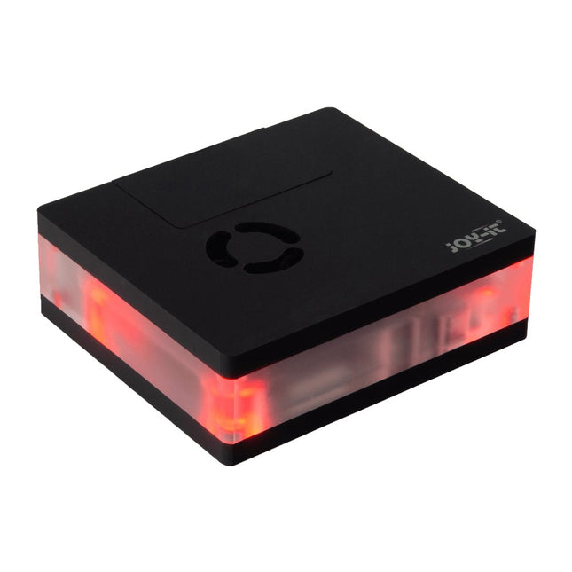
This multimedia case for all Raspberry Pi 4 models is characterized by high functionality, modern design and a sumptuous equipment:
Integrated IR receiver, controllable with almost all IR remote controls
Controllable LED lighting
Switching on/off, controlling additional functions of the Raspberry Pi
Active, quiet cooling
Toolless, magnetic assembly
All connections of the Raspberry Pi are on the backside
GPIO port is accessible via separate lid
Perfect as a multimedia platform in the living room, desktop device or for the use in digital signage.
Specifications
Material
Acryl
Color
Black
Compatible to
Raspberry Pi 4
Power supply
5 VDC (USB-C)
Microcontroller
STM32F030F4P
Infrared receiver
TSOP4838
LEDs
4x WS2812Mini
Led out connections
1x USB-C, 1x Aux, 2x microHDMIFrom Raspberry Pi: 2x USB-A 3.0, 2x USB-A 2.0, 1x RJ45
Weight
280 g
Dimensions
113 x 100 x 38 mm
Scope of delivery
Multimedia case, adapter board, control board, Aux adapter cable
Downloads
Datasheet (177.9 KB)
Manual (3.5 MB)
Expert Guide (6.5 MB)
Firmware v1.0.9-beta (11.2 KB)
Addons for LibreElec 9 (2.6 MB)
Code Examples
Addon - Multimedia Case Configuration
Addon - LED Configuration
Addon - IR Control Configuration
Prepared LibreElec Image
Prepared LibreElec Image 10.BETA
GitHub
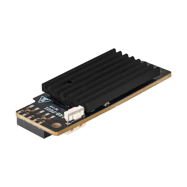
Wide Range Power Supply for Raspberry Pi
With the PiEnergy Mini, you can operate your Raspberry Pi with a voltage of 6 to 36 V DC. You can use the button integrated on the board to both power up and power down your Raspberry Pi.
Communication with the Raspberry Pi is via GPIO4, but this connection can also be cut by removing a resistor to use the pin freely. Thanks to the ultra-flat design, it can also be used in many housings. The pin header is included and not soldered on to keep the design even flatter.
Specifications
Input voltage
6 to 36 V DC
Output voltage
5.1 V
Output current
Up to 3 A (active ventilation recommended for additionally connected loads)
Cable cross-section at the power input
0.2-0.75 mm²
Interface to the Raspberry Pi
GPIO4
Microcontroller
ATtiny5
Further connections
5 V fan connector (2-pin/2.54 mm)Solder pads for external on/off switch
Compatible with
Raspberry Pi 3, 4, 5
Dimensions
23 x 56 x 11 mm
Included
Board with mounted heat sink
Pin header (2x5)
Spacer, screw, nut
Downloads
Datasheet (English)
Datasheet (Italiano)
Manual (English)
Manual (Italiano)
This bundle includes both volumes of "KiCad Like a Pro" (4th edition 2024). In Fundamentals and Projects (normal price: €49.95), you'll learn how to use KiCad through a practical approach, helping you quickly become productive and start designing your own boards. Advanced Projects and Recipes (normal price: €44.95) allows you to practice your new KiCad skills by challenging yourself with a series of real-world projects.
The latest iteration of KiCad, the world’s best free-to-use Printed Circuit Board tool, is packed with features usually found only in expensive commercial CAD tools. This modern, cross-platform application suite built around schematic and design editors, with auxiliary applications is a stable and mature PCB tool. KiCad 8 is a perfect fit for electronic engineers and makers.
Here are the most significant improvements and features in KiCad 8, both over and under the hood:
Modern user interface, completely redesigned from earlier versions
Improved and customizable electrical and design rule checkers
Theme editor allowing you to customize KiCad on your screen
Ability to import projects from Eagle, CADSTART, and more
Python scripting API
Improved integrated SPICE circuit simulator
Multi-sheet schematics
Filters define selectable elements
Enhanced interactive router helps you draw single tracks and differential pairs with precision
New or enhanced tools to draw tracks, measure distances, tune track lengths, etc.
Advanced interactive router
Built-in bill of materials generator
Realistic ray-tracing capable 3D viewer
Customizable teardrops
Plug-in manager for quick installation of themes, libraries and functionalities such as autorouters and BOM generators
The first book KiCad Like A Pro – Fundamentals and Projects will teach you to use KiCad through a practical approach. It will help you become productive quickly and start designing your own boards. Example projects illustrate the basic features of KiCad, even if you have no prior knowledge of PCB design. The author describes the entire workflow from schematic entry to the intricacies of finalizing the files for PCB production and offers sound guidance on the process.
The second book KiCad Like A Pro – Advanced Projects and Recipes will help you to practice your new KiCad skills by challenging you in a series of real-world projects. The projects are supported by a comprehensive set of recipes with detailed instructions on how to achieve a variety of simple and complex tasks. Design the PCBs for a solar power supply, an LED matrix array, an Arduino-powered datalogger, and a custom ESP32 board. Understand the finer details of the interactive router, how to manage KiCad project teams with Git, how to use an autorouter on 2 and 4-layer PCBs, and much more.
This bundle includes both volumes of "KiCad Like a Pro" (4th edition 2024). In Fundamentals and Projects (normal price: €39.95), you'll learn how to use KiCad through a practical approach, helping you quickly become productive and start designing your own boards. Advanced Projects and Recipes (normal price: €34.95) allows you to practice your new KiCad skills by challenging yourself with a series of real-world projects.
The latest iteration of KiCad, the world’s best free-to-use Printed Circuit Board tool, is packed with features usually found only in expensive commercial CAD tools. This modern, cross-platform application suite built around schematic and design editors, with auxiliary applications is a stable and mature PCB tool. KiCad 8 is a perfect fit for electronic engineers and makers.
Here are the most significant improvements and features in KiCad 8, both over and under the hood:
Modern user interface, completely redesigned from earlier versions
Improved and customizable electrical and design rule checkers
Theme editor allowing you to customize KiCad on your screen
Ability to import projects from Eagle, CADSTART, and more
Python scripting API
Improved integrated SPICE circuit simulator
Multi-sheet schematics
Filters define selectable elements
Enhanced interactive router helps you draw single tracks and differential pairs with precision
New or enhanced tools to draw tracks, measure distances, tune track lengths, etc.
Advanced interactive router
Built-in bill of materials generator
Realistic ray-tracing capable 3D viewer
Customizable teardrops
Plug-in manager for quick installation of themes, libraries and functionalities such as autorouters and BOM generators
The first book KiCad Like A Pro – Fundamentals and Projects will teach you to use KiCad through a practical approach. It will help you become productive quickly and start designing your own boards. Example projects illustrate the basic features of KiCad, even if you have no prior knowledge of PCB design. The author describes the entire workflow from schematic entry to the intricacies of finalizing the files for PCB production and offers sound guidance on the process.
The second book KiCad Like A Pro – Advanced Projects and Recipes will help you to practice your new KiCad skills by challenging you in a series of real-world projects. The projects are supported by a comprehensive set of recipes with detailed instructions on how to achieve a variety of simple and complex tasks. Design the PCBs for a solar power supply, an LED matrix array, an Arduino-powered datalogger, and a custom ESP32 board. Understand the finer details of the interactive router, how to manage KiCad project teams with Git, how to use an autorouter on 2 and 4-layer PCBs, and much more.
Mastering PCB design with real-world projects
This book builts on KiCad Like a Pro – Fundamentals and Projects and aims to help you practice your new KiCad skills by challenging you in a series of real-world projects. The projects are supported by a comprehensive set of recipes with detailed instructions on how to achieve a variety of simple and complex tasks. Design the PCBs for a solar power supply, an LED matrix array, an Arduino-powered datalogger, and a custom ESP32 board. Understand the finer details of the interactive router, how to manage KiCad project teams with Git, how to use an autorouter on 2 and 4-layer PCBs, and much more.
KiCad 8 is a modern, cross-platform application suite built around schematic and design editors. This stable and mature PCB tool is a perfect fit for electronic engineers and makers. With KiCad 8, you can create PCBs of any complexity and size without the constraints associated with the commercial packages.
Here are the most significant improvements and features in KiCad 8, both over and under the hood:
Modern user interface, completely redesigned from earlier versions
Improved and customizable electrical and design rule checkers
Theme editor allowing you to fully customize the look of KiCad on your screen
Ability to import projects from Eagle, CADSTART, and more
An improved and tightly integrated SPICE circuit simulator
Autorouting with the Freerouting plugin
Filters define which elements of a layout are selectable
Enhanced interactive router helps you draw single tracks and differential pairs with precision
New or enhanced tools to draw tracks, measure distances, tune track lengths, etc.
Enhanced tool for creating filled zones
A customizable coordinate system facilitates data exchange with other CAD applications
Realistic ray-tracing capable 3D viewer
Differential pair routing
Rich repositories of symbol, footprint, and 3D shape libraries
Python scripting API for programmatic customization and extensions
Improved footprint wizard for fast custom footprints
Getting started with the world’s best open-source PCB tool
The latest iteration of KiCad, the world’s best free-to-use Printed Circuit Board tool, is packed with features usually found only in expensive commercial CAD tools. This modern, cross-platform application suite built around schematic and design editors, with auxiliary applications is a stable and mature PCB tool. KiCad 8 is a perfect fit for electronic engineers and makers.
Here are the most significant improvements and features in KiCad 8, both over and under the hood:
Modern user interface, completely redesigned from earlier versions
Improved and customizable electrical and design rule checkers
Theme editor allowing you to customize KiCad on your screen
Ability to import projects from Eagle, CADSTART, and more
Python scripting API
Improved integrated SPICE circuit simulator
Multi-sheet schematics
Filters define selectable elements
Enhanced interactive router helps you draw single tracks and differential pairs with precision
New or enhanced tools to draw tracks, measure distances, tune track lengths, etc.
Advanced interactive router
Built-in bill of materials generator
Realistic ray-tracing capable 3D viewer
Customizable teardrops
Plug-in manager for quick installation of themes, libraries and functionalities such as autorouters and BOM generators
This book will teach you to use KiCad through a practical approach. It will help you become productive quickly and start designing your own boards. Example projects illustrate the basic features of KiCad, even if you have no prior knowledge of PCB design.
The author describes the entire workflow from schematic entry to the intricacies of finalizing the files for PCB production and offers sound guidance on the process. Further full-fledged projects, of incremental difficulty, will be presented in a second book, together with a variety of advanced recipes.
Get Cracking with the Arduino Nano V3, Nano Every, and Nano 33 IoT
The seven chapters in this book serve as the first step for novices and microcontroller enthusiasts wishing to make a head start in Arduino programming. The first chapter introduces the Arduino platform, ecosystem, and existing varieties of Arduino Nano boards. It also teaches how to install various tools needed to get started with Arduino Programming. The second chapter kicks off with electronic circuit building and programming around your Arduino. The third chapter explores various buses and analog inputs. In the fourth chapter, you get acquainted with the concept of pulse width modulation (PWM) and working with unipolar stepper motors.
In the fifth chapter, you are sure to learn about creating beautiful graphics and basic but useful animation with the aid of an external display. The sixth chapter introduces the readers to the concept of I/O devices such as sensors and the piezo buzzer, exploring their methods of interfacing and programming with the Arduino Nano. The last chapter explores another member of Arduino Nano family, Arduino Nano 33 IoT with its highly interesting capabilities. This chapter employs and deepens many concepts learned from previous chapters to create interesting applications for the vast world of the Internet of Things.
The entire book follows a step-by-step approach to explain concepts and the operation of things. Each concept is invariably followed by a to-the-point circuit diagram and code examples. Next come detailed explanations of the syntax and the logic used. By closely following the concepts, you will become comfortable with circuit building, Arduino programming, the workings of the code examples, and the circuit diagrams presented. The book also has plenty of references to external resources wherever needed.
An archive file (.zip) comprising the software examples and Fritzing-style circuit diagrams discussed in the book may be downloaded free of charge below.
An Ultra-Rapid Programming Course
This book serves as the very first step to for novices to learn Python programming. The book is divided into ten chapters. In the first chapter, readers are introduced to the basics of Python. It has the detailed instructions for installation on various platforms such as macOS, Windows, FreeBSD, and Linux. It also covers the other aspects of Python programming such as IDEs and Package Manager. The second chapter is where the readers get an opportunity to have a detailed hands-on with Python programming. It covers a group of built-in data structures popularly known as Python Collections. The third chapter covers the important concepts of strings, functions, and recursion.
The fourth chapter focuses on the Object-Oriented Programming with Python. The fifth chapter discusses most commonly used custom data structures such as stack and queue. The sixth chapter spurs the creativity of the readers with Python’s Turtle graphics library. The seventh chapter explores animations and game development using the Pygame library. The eighth chapter covers handling data stored in a variety of file formats. The ninth chapter covers the area of Image processing with Wand library in Python. The tenth and the final chapter presents an array of assorted handy topics in Python.
The entire book follows a step-by-step approach. The explanation of the topic is always followed by a detailed code example. The code examples are also explained in suitable detail and they are followed by the output in the form of text or screenshot wherever possible. Readers will become comfortable with Python programming language by closely following the concepts and the code examples in this book. The book also has references to external resources for readers to explore further.
A download of the software code, and links to tutorial videos can be found on the Elektor website.