Products
-
Elektor Publishing Microcontroller Basics with PIC
In this book the author presents all essential aspects of microcontroller programming, without overloading the reader with unnecessary or quasi-relevant bits of information. Having read the book, you should be able to understand as well as program, 8-bit microcontrollers. The introduction to microcontroller programming is worked out using microcontrollers from the PIC series. Not exactly state-of-the-art with just 8 bits, the PIC micro has the advantage of being easy to comprehend. It is offered in a DIP enclosure, widely available and not overly complex. The entire datasheet of the PIC micro is shorter by decades than the description of the architecture outlining the processor section of an advanced microcontroller. Simplicity has its advantages here. Having mastered the fundamental operation of a microcontroller, you can easily enter into the realms of advanced softcores later. Having placed assembly code as the executive programming language in the foreground in the first part of the book, the author reaches a deeper level with ‘C’ in the second part. Cheerfully alongside the official subject matter, the book presents tips & tricks, interesting measurement technology, practical aspects of microcontroller programming, as well as hands-on options for easier working, debugging and faultfinding.
€ 39,95
Members € 35,96
-
Elektor Digital Microcontroller Basics with PIC (E-book)
In this book the author presents all essential aspects of microcontroller programming, without overloading the reader with unnecessary or quasi-relevant bits of information. Having read the book, you should be able to understand as well as program, 8-bit microcontrollers. The introduction to microcontroller programming is worked out using microcontrollers from the PIC series. Not exactly state-of-the-art with just 8 bits, the PIC micro has the advantage of being easy to comprehend. It is offered in a DIP enclosure, widely available and not overly complex. The entire datasheet of the PIC micro is shorter by decades than the description of the architecture outlining the processor section of an advanced microcontroller. Simplicity has its advantages here. Having mastered the fundamental operation of a microcontroller, you can easily enter into the realms of advanced softcores later. Having placed assembly code as the executive programming language in the foreground in the first part of the book, the author reaches a deeper level with ‘C’ in the second part. Cheerfully alongside the official subject matter, the book presents tips & tricks, interesting measurement technology, practical aspects of microcontroller programming, as well as hands-on options for easier working, debugging and faultfinding.
€ 32,95
Members € 26,36
-
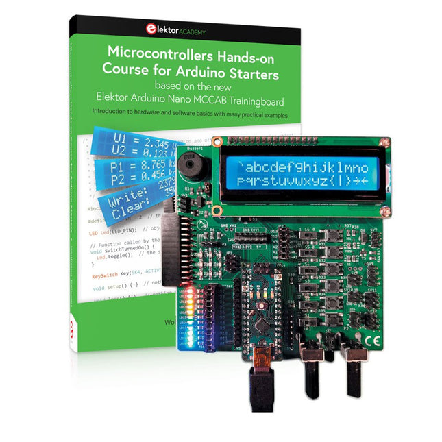
Elektor Bundles Microcontrollers Hands-on Course for Arduino Starters (Bundle)
Realize your own projects with the Elektor Arduino Nano MCCAB Training Board The microcontroller is probably the most fascinating subfield of electronics. Due to the multitude of functions, it combines on its chip, it is a universal multi-tool for developers to realize their projects. Practically every device of daily use today is controlled by a microcontroller. However, for an electronic layman, realizing his own ideas with a microcontroller has so far remained a pipe dream due to its complexity. The Arduino concept has largely simplified the use of microcontrollers, so that now even laymen can realize their own electronics ideas with a microcontroller. Book & Hardware in the Bundle: 'Learning by Doing' This book, which is included in the bundle, shows how you can realize your own projects with a microcontroller even without much experience in electronics and programming languages. It is a microcontrollers hands-on course for starters, because after an overview of the internals of the microcontroller and an introduction to the programming language C, the focus of the course is on the practical exercises. The reader acquires the necessary knowledge by 'learning by doing': in the extensive practical section with 12 projects and 46 exercises, what is learned in the front part of the book is underpinned with many examples. The exercises are structured in such a way that the user is given a task to solve using the knowledge built up in the theoretical part of the book. Each exercise is followed by a sample solution that is explained and commented on in detail, which helps the user to solve problems and compare it with his own solution. Arduino IDE The Arduino IDE is a software development environment that can be downloaded for free to your own PC and that contains the entire software package needed for your own microcontroller projects. You write your programs ('apps') with the IDE’s editor in the C programming language. You translate them into the bits and bytes that the microcontroller understands using the Arduino IDE's built-in compiler, and then load them into the microcontroller's memory on the Elektor Arduino MCCAB Nano Training Board via a USB cable. Query or control external sensors, motors or assemblies In addition to an Arduino Nano microcontroller module, the Elektor Arduino Nano MCCAB Training Board contains all the components required for the exercises, such as light-emitting diodes, switches, pushbuttons, acoustic signal transmitters, etc. External sensors, motors or assemblies can also be queried or controlled with this microcontroller training system. Specifications (Arduino Nano MCCAB Training Board) Power Supply Via the USB connection of the connected PC or an external power supply unit (not included) Operating Voltage +5 Vcc Input Voltage All inputs 0 V to +5 V VX1 and VX2 +8 V to +12 V (only when using an external power supply) Hardware periphery LCD 2x16 characters Potentiometer P1 & P2 JP3: selection of operating voltage of P1 & P2 Distributor SV4: Distributor for the operating voltagesSV5, SV6: Distributor for the inputs/outputs of the microcontroller Switches and buttons RESET button on the Arduino Nano module 6x pushbutton switches K1 ... K6 6x slide switches S1 ... S6 JP2: Connection of the switches with the inputs of the microcontroller Buzzer Piezo buzzer Buzzer1 with jumper on JP6 Indicator lights 11 x LED: Status indicator for the inputs/outputs LED L on the Arduino Nano module, connected to GPIO D13 JP6: Connection of LEDs LD10 ... LD20 with GPIOs D2 ... D12 Serial interfacesSPI & I²C JP4: Selection of the signal at pin X of the SPI connector SV12 SV9 to SV12: SPI interface (3.3 V/5 V) or I²C interface Switching output for external devices SV1, SV7: Switching output (maximum +24 V/160 mA, externally supplied) SV2: 2x13 pins for connection of external modules 3x3 LED matrix(9 red LEDs) SV3: Columns of the 3x3 LED matrix (outputs D6 ... D8) JP1: Connection of the rows with the GPIOs D3 ... D5 Software Library MCCABLib Control of hardware components (switches, buttons, LEDs, 3x3 LED matrix, buzzer) on the MCCAB Training Board Operating Temperature Up to +40 °C Dimensions 100 x 100 x 20 mm Specifications (Arduino Nano) Microcontroller ATmega328P Architecture AVR Operating Voltage 5 V Flash Memory 32 KB, of which 2 KB used by bootloader SRAM 2 KB Clock Speed 16 MHz Analog IN Pins 8 EEPROM 1 KB DC Current per I/O Pins 40 mA on one I/O pin, total maximum 200 mA on all pins together Input Voltage 7-12 V Digital I/O Pins 22 (6 of which are PWM) PWM Output 6 Power Consumption 19 mA Dimensions 18 x 45 mm Weight 7 g Included 1x Elektor Arduino Nano MCCAB Training Board 1x Arduino Nano 1x Book: Microcontrollers Hands-on Course for Arduino Starters
€ 139,95€ 109,95
Members identical
-
Elektor Digital Microprocessor Design Using Verilog HDL (E-book)
If you have the right tools, designing a microprocessor shouldn’t be complicated. The Verilog hardware description language (HDL) is one such tool. It can enable you to depict, simulate, and synthesize an electronic design, and thus increase your productivity by reducing the overall workload associated with a given project.Monte Dalrymple’s Microprocessor Design Using Verilog HDL is a practical guide to processor design in the real world. It presents the Verilog HDL in a straightforward fashion and serves as a detailed introduction to reducing the computer architecture and as an instruction set to practice. You’re led through the microprocessor design process from start to finish, and essential topics ranging from writing in Verilog to debugging and testing are laid bare.The book details the following, and more: Verilog HDL Review: data types, bit widths/labeling, operations, statements, and design hierarchy Verilog Coding Style: files vs. modules, indentation, and design organization Design Work: instruction set architecture, external bus interface, and machine cycle Microarchitecture: design spreadsheet and essential worksheets (e.g., Operation, Instruction Code, and Next State) Writing in Verilog: choosing encoding, assigning states in a state machine, and files (e.g., defines.v, hierarchy.v, machine.v) Debugging, Verification, and Testing: debugging requirements, verification requirements, testing requirements, and the test bench Post Simulation: enhancements and reduction to practice Monte Dalrymple received a BSEE (with highest honors) and an MSEE from the University of California at Berkeley, where he was elected to Phi Beta Kappa. Monte started his career at Zilog, where he designed a number of successful products, including the Serial Communication Controller (SCC) family and the Universal Serial Controller (USC) family. He was also the architect and lead designer of the Z380 microprocessor. Monte started his own company, Systemyde International Corp., in 1995, and has been doing contract design work ever since. He designed all five generations of Rabbit microprocessors, a Z180 clone that is flying on the Juno mission to Jupiter, and a Z8000 clone that flies in a commercial avionics air data computer. Monte holds 16 patents as well as both amateur and commercial radio licenses. Monte wrote 10 articles for Circuit Cellar magazine between 1996 and 2010. He recently completed a side project to replace the CPU in an HP-41C calculator with a modern FPGA-based version.
€ 29,95
Members € 23,96
-
Elektor Digital MicroPython for Microcontrollers (E-book)
Projects with Thonny-IDE, uPyCraft-IDE, and ESP32 The 'Python' programming language has enjoyed an enormous upswing in recent years. Not least, various single-board systems such as the Raspberry Pi have contributed to its popularity. But Python has also found widespread use in other fields, such as artificial intelligence (AI) or machine learning (ML). It is obvious, therefore, to use Python or the 'MicroPython' variant for use in SoCs (Systems on Chip) as well. Powerful controllers such as the ESP32 from Espressif Systems offer excellent performance as well as Wi-Fi and Bluetooth functionality at an affordable price. With these features, the Maker scene has been taken by storm. Compared to other controllers, the ESP32 has a significantly larger flash and SRAM memory, as well as a much higher CPU speed. Due to these characteristics, the chip is not only suitable for classic C applications, but also for programming with MicroPython. This book introduces the application of modern one-chip systems. In addition to the technical background, the focus is on MicroPython itself. After the introduction to the language, the programming skills learned are immediately put into practice. The individual projects are suitable for use in the laboratory as well as for everyday applications. So, in addition to the actual learning effect, the focus is also on the joy of building complete and useful devices. By using laboratory breadboards, circuits of all kinds can be realized with little effort, turning the testing and debugging of the 100% homebrew projects into an instructive pleasure. The various applications, such as weather stations, digital voltmeters, ultrasound range finders, RFID card readers or function generators, make the projects presented ideally suited for practical courses or subject and study work in the natural sciences, or in science and technology classes.
€ 32,95
Members € 26,36
-

Micsig Micsig CP2100A AC/DC Current Probe
Features Bandwidth: DC-800 KHz Maximum measurable current: 100 Apk (70.7 Arms) Max. conductor diameter: 13 mm Auto & Manual "Zero" function Directly powered by USB port Standard BNC interface, compatible with any oscilloscope Specifications Bandwidth DC-800 KHz Rise time <= 583 ns Ranges 10 A / 100 A Output sensitivity 0.1 V/A (10 A) 0.01 V/A (100 A) DC accuracy 3% ±50 mA (10 A) 4% ±50 mA (100 A, 500 mA - 40 Apk) 15% (100 A, 40 Apk -100 Apk) Signal delay < 150 ns (10 A) < 200ns (100 A) Current measurement range 50 mA - 10 Apk (10 A) 1 A - 100 Apk (100 A) Max. Voltage CAT III 300 V CAT II 600 V Power supply DC 5 V Downloads Quick Guide Datasheet Manual
€ 309,76
-
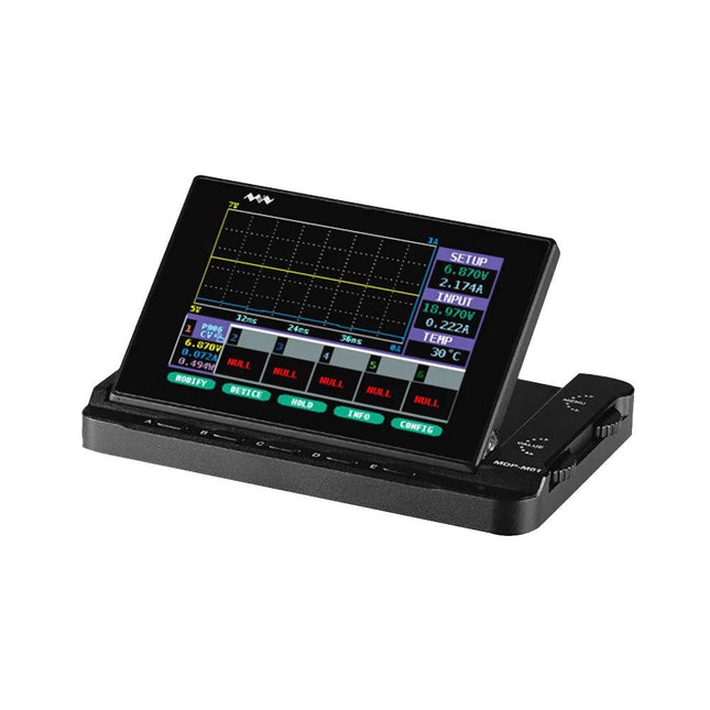
Miniware Miniware MDP-M01 Smart Digital Monitor
MDP-M01 is a display control module equipped with a 2.8-inch TFT display screen, the screen can be turned 90 degrees, which is convenient for users to view data and waveform. MDP-M01 can realize online display and control with MDP-P906 mini digital power supply modules and other modules of MDP system through 2.4 GHz wireless communication, and can control up to 6 sub-modules at the same time. Specifications Screen size 2.8" TFT Screen resolution 240 x 320 Power Micro USB power input, or taking power from sub-module via dedicated power cable Input DC 5 V/0.3 A Other functions Can control up to 6 sub-modulesUpgrade firmware through Micro USB Dimensions 107 x 66 x 13.6 mm Weight 133 g Included 1x MDP-M01 Smart Digital Monitor 1x Cable (2.5 mm jack to Micro USB) Downloads User Manual v3.4 Firmware v1.32
€ 79,00
-
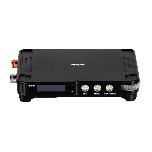
Miniware Miniware MDP-P906 Digital Power Supply (300 W)
MDP-P906 has a built-in cooling fan, and maximum output power of up to 300 W, which meets a wider range of testing needs and application scenarios. Through 2.4 GHz wireless communication, it can be connected to MDP-M01 Smart Digital Monitor module to realize the free combination of multiple channels of 300 W per channel. MDP-P906 has the index, stability and reliability comparable to a professional power supply. It can output pure current, and provide powerful functions such as programmable output, timing output, timing control, automatic compensation, boost mode, etc., making itself a real cost-effective, smart and customized programmable linear DC power supply. MDP-P906 adopts a precision CNC machined aluminum alloy shell, with fine workmanship, novel, mini and beautiful appearance, it completely subverts the rigid image of traditional desktop power supply. With stackable modular design and wireless communication function, MDP-P906 can work independently or paired, both on the workbench, and be carried out for on-site maintenance. MDP-P906 is a perfect solution for electronic engineer, especially field application engineers to meet different needs of power sources. Built-in silent cooling fan, instant cooling, ensure a stable and efficient output! Smart linear compensation, constant voltage & constant current Positive & negative output, series boost, parallel current sharing Applications Universal tests and teaching experiments in R&D laboratory Maintenance of digital products Property verification and fault diagnosis of devices and circuits Emergency power supply for model airplanes and vehicles Power supply testing of RF and microwave circuits or modules Quality control and quality inspection Supply purified power for high-accuracy digital-analog hybrid circuits and Hi-Fi audio devices Specifications Input DC 4.2-30 V/14 A (Max)QC 3.0/PD2.0, 20 V/5 A (Max) Output 0-30 V/0-10 A, 300 W (Max) Conversion efficiency 95% Output resolution 10 mV/2 mA, up to 1 mV/1 mA via Display Control module Output accuracy 0.03%+5 mV0.05%+2 mV Adjustment rate Load adjustment rate <±0.01%Power adjustment rate <±0.01% Ripple and noise <250 uVrms, 3 mVpp; 2 mArms Transient response <4 uS Safety protections Input over-voltage, under-voltage, reverse connection protection, output over-current, back-flow protection and over-temperature protection Others Automatically shut-down and enter micro-power modeSupport USB firmware upgrade Dimensions 112 x 66 x 20 mm Weight 181 g Included 1x MDP-P906 Digital Power Supply 2x Output Cable 1x User Manual Downloads User Manual v1.1 Firmware v1.32
€ 171,95
-

Elektor Digital MIT App Inventor Projects (E-book)
50+ Android Apps with Raspberry Pi, ESP32 and Arduino This book is about developing apps for Android compatible mobile devices using the MIT App Inventor online development environment. MIT App Inventor projects can be in either standalone mode or use an external processor. In standalone mode, the developed application runs only on the mobile device (e.g. Android). In external processor-based applications, the mobile device communicates with an external microcontroller-based processor, such as Raspberry Pi, Arduino, ESP8266, ESP32, etc. In this book, many tested and fully working projects are given both in standalone mode and using an external processor. Full design steps, block programs, circuit diagrams, QR codes and full program listings are given for all projects. The projects developed in this book include: Using the text-to-speech component Intonating a received SMS message Sending SMS messages Making telephone calls using a contacts list Using the GPS and Pin-pointing our location on a map Speech recognition and speech translation to another language Controlling multiple relays by speech commands Projects for the Raspberry Pi, ESP32 and Arduino using Bluetooth and Wi-Fi MIT APP Inventor and Node-RED projects for the Raspberry Pi The book is unique in that it is currently the only book that teaches how to develop projects using Wi-Fi and Node-RED with MIT App Inventor. The book is aimed at students, hobbyists, and anyone interested in developing apps for mobile devices. All projects presented in this book have been developed using the MIT App Inventor visual programming language. There is no need to write any text-based programs. All projects are compatible with Android-based mobile devices. Full program listings for all projects as well as detailed program descriptions are given in the book. Users should be able to use the projects as they are presented, modifying them to suit their own needs.
€ 32,95
Members € 26,36
-
Elektor Digital Modern High-End Valve Amplifiers (E-book)
Valve Amplifiers are regarded by many to be the ne plus ultra when it comes to processing audio signals. The combination of classical technology and modern components has resulted in a revival of the valve amplifier. The use of toraidal-core output transformers, developed by the author over the past 15 years, has contributed to this revival. The most remarkable features of these transformers are their extremely wide frequency ranges and their very low levels of linear and nonlinear distortion. This book explains the whys and wherefores of toroidal output transformers at various technical levels, starting with elementary concepts and culminating in complete mathematical descriptions. In all of this, the interactions of the output valves, transformer and loudspeaker form the central theme. Next come the practical aspects. The schematic diagram of a valve amplifier often appears to be very simple at first glance, but anyone who has built a modern valve amplifier knows that a lot of critical details are hidden behind this apparent simplicity. These are discussed extensively, in connection with designs for amplifiers with output powers ranging from 10 to 100 watts. Finally, the author gives some attention to a number of special valve amplifiers, and to the theory and practice of negative feedback. In summary, this book offers innovative solutions for achieving perfect audio quality. Do-it-yourself builders, as well as persons who want to gain a deeper technical understanding of the complex world of audio transformers, valve amplifiers and audio signal processing, will find this book a rich and useful source of information.
€ 34,95
Members € 27,96
-
MonkMakes MonkMakes ServoClip
An adapter for connecting a servo meter with croc/alligator clips. This is a handy little clip to connect a servo motor with 5.4 mm header socket using alligator clips. It is ideal for use with boards like the BBC micro:bit and Adafruit's Circuit Playground Express or Gemma. Width: 27 mm Height: 35 mm Downloads Datasheet
€ 3,95€ 1,58
Members identical
-
Elektor Digital Motor Control - Projects with Arduino & Raspberry Pi (E-book)
This book is about DC electric motors and their use in Arduino and Raspberry Pi Zero W based projects. The book includes many tested and working projects where each project has the following sub-headings: Title of the project Description of the project Block diagram Circuit diagram Project assembly Complete program listing of the project Full description of the program The projects in the book cover the standard DC motors, stepper motors, servo motors, and mobile robots. The book is aimed at students, hobbyists, and anyone else interested in developing microcontroller based projects using the Arduino Uno or the Raspberry Pi Zero W. One of the nice features of this book is that it gives complete projects for remote control of a mobile robot from a mobile phone, using the Arduino Uno as well as the Raspberry Pi Zero W development boards. These projects are developed using Wi-Fi as well as the Bluetooth connectivity with the mobile phone. Readers should be able to move a robot forward, reverse, turn left, or turn right by sending simple commands from a mobile phone. Full program listings of all the projects as well as the detailed program descriptions are given in the book. Users should be able to use the projects as they are presented, or modify them to suit to their own needs.
€ 29,95
Members € 23,96
-
Elektor Publishing MSP430 Microcontroller Essentials
Architecture, Programming and Applications The MSP430 is a popular family of microcontrollers from Texas Instruments. In this book we will work with the smallest type, which is the powerful MSP430G2553. We will look at the capabilities of this microcontroller in detail, as it is well-suited for self-made projects because it is available in a P-DIP20 package. We will take a closer look at the microcontroller and then build, step by step, some interesting applications, including a 'Hello World' blinking LED and a nice clock application, which can calculate the day of the week based on the date. You also will learn how to create code for the MSP microcontroller in assembler. In addition to that, we will work with the MSP-Arduino IDE, which makes it quite easy to create fast applications without special in-depth knowledge of the microcontrollers. All the code used in the book is available for download from the Elektor website.
€ 39,95
Members € 35,96
-
Elektor Digital MSP430 Microcontroller Essentials (E-book)
Architecture, Programming and Applications The MSP430 is a popular family of microcontrollers from Texas Instruments. In this book we will work with the smallest type, which is the powerful MSP430G2553. We will look at the capabilities of this microcontroller in detail, as it is well-suited for self-made projects because it is available in a P-DIP20 package. We will take a closer look at the microcontroller and then build, step by step, some interesting applications, including a 'Hello World' blinking LED and a nice clock application, which can calculate the day of the week based on the date. You also will learn how to create code for the MSP microcontroller in assembler. In addition to that, we will work with the MSP-Arduino IDE, which makes it quite easy to create fast applications without special in-depth knowledge of the microcontrollers. All the code used in the book is available for download from the Elektor website.
€ 32,95
Members € 26,36
-
Elektor Digital Multitasking with Raspberry Pi (E-book)
Multitasking and multiprocessing have become a very important topic in microcontroller-based systems, namely in complex commercial, domestic, and industrial automation applications. As the complexity of projects grows, more functionalities are demanded from the projects. Such projects require the use of multiple inter-related tasks running on the same system and sharing the available resources, such as the CPU, memory, and input-output ports. As a result of this, the importance of multitasking operations in microcontroller-based applications has grown steadily over the last few years. Many complex automation projects now make use of some form of a multitasking kernel. This book is project-based and its main aim is to teach the basic features of multitasking using the Python 3 programming language on Raspberry Pi. Many fully tested projects are provided in the book using the multitasking modules of Python. Each project is described fully and in detail. Complete program listings are given for each project. Readers should be able to use the projects as they are, or modify them to suit their own needs. The following Python multitasking modules have been described and used in the projects: Fork Thread Threading Subprocess Multiprocessing The book includes simple multitasking projects such as independently controlling multiple LEDs, to more complex multitasking projects such as on/off temperature control, traffic lights control, 2-digit, and 4-digit 7-segment LED event counter, reaction timer, stepper motor control, keypad based projects, car park controller, and many more. The fundamental multitasking concepts such as process synchronization, process communication, and memory sharing techniques have been described in projects concerning event flags, queues, semaphores, values, and so on.
€ 32,95
Members € 26,36
-
Elektor Publishing Node-RED and Raspberry Pi Pico W
From basics to flows for sensors, automation, motors, MQTT, and cloud services This book is a learning guide and a reference. Use it to learn Node-RED, Raspberry Pi Pico W, and MicroPython, and add these state-of-the-art tools to your technology toolkit. It will introduce you to virtual machines, Docker, and MySQL in support of IoT projects based on Node-RED and the Raspberry Pi Pico W. This book combines several elements into a platform that powers the development of modern Internet of Things applications. These elements are a flow-based server, a WiFi-enabled microcontroller, a high-level programming language, and a deployment technology. Combining these elements gives you the tools you need to create automation systems at any scale. From home automation to industrial automation, this book will help you get started. Node-RED is an open-source flow-based development tool that makes it easy to wire together devices, APIs, and online services. Drag and drop nodes to create a flowchart that turns on your lights at sunset or sends you an email when a sensor detects movement. Raspberry Pi Pico W is a version of the Raspberry Pi Pico with added 802.11n Wi-Fi capability. It is an ideal device for physical computing tasks and an excellent match to the Node-RED. Quick book facts Project-based learning approach. Assumes no prior knowledge of flow-based programming tools. Learn to use essential infrastructure tools in your projects, such as virtual machines, Docker, MySQL and useful web APIs such as Google Sheets and OpenWeatherMap. Dozens of mini-projects supported by photographs, wiring schematics, and source code. Get these from the book GitHub repository. Step-by-step instructions on everything. All experiments are based on the Raspberry Pi Pico W. A Wi-Fi network is required for all projects. Hardware (including the Raspberry Pi Pico W) is available as a kit. Downloads GitHub
€ 49,95
Members € 44,96
-
Elektor Digital Node-RED and Raspberry Pi Pico W (E-book)
From basics to flows for sensors, automation, motors, MQTT, and cloud services This book is a learning guide and a reference. Use it to learn Node-RED, Raspberry Pi Pico W, and MicroPython, and add these state-of-the-art tools to your technology toolkit. It will introduce you to virtual machines, Docker, and MySQL in support of IoT projects based on Node-RED and the Raspberry Pi Pico W. This book combines several elements into a platform that powers the development of modern Internet of Things applications. These elements are a flow-based server, a WiFi-enabled microcontroller, a high-level programming language, and a deployment technology. Combining these elements gives you the tools you need to create automation systems at any scale. From home automation to industrial automation, this book will help you get started. Node-RED is an open-source flow-based development tool that makes it easy to wire together devices, APIs, and online services. Drag and drop nodes to create a flowchart that turns on your lights at sunset or sends you an email when a sensor detects movement. Raspberry Pi Pico W is a version of the Raspberry Pi Pico with added 802.11n Wi-Fi capability. It is an ideal device for physical computing tasks and an excellent match to the Node-RED. Quick book facts Project-based learning approach. Assumes no prior knowledge of flow-based programming tools. Learn to use essential infrastructure tools in your projects, such as virtual machines, Docker, MySQL and useful web APIs such as Google Sheets and OpenWeatherMap. Dozens of mini-projects supported by photographs, wiring schematics, and source code. Get these from the book GitHub repository. Step-by-step instructions on everything. All experiments are based on the Raspberry Pi Pico W. A Wi-Fi network is required for all projects. Hardware (including the Raspberry Pi Pico W) is available as a kit. Downloads GitHub
€ 39,95
Members € 31,96
-
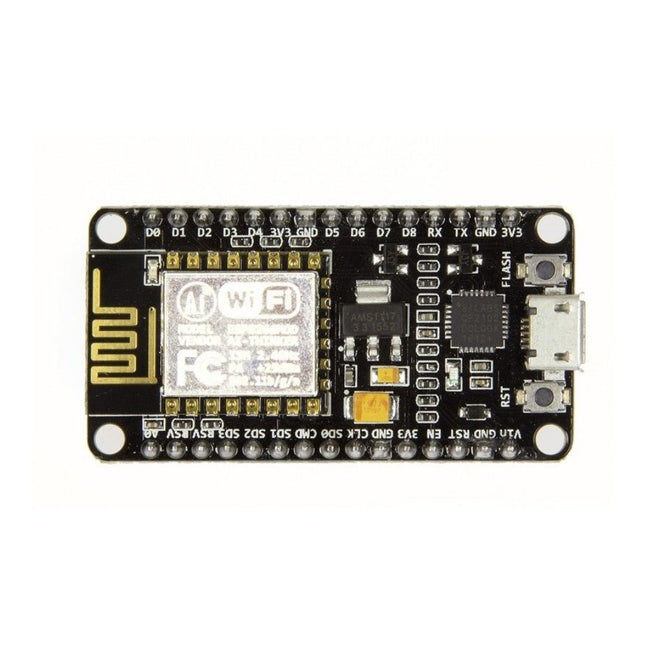
Espressif NodeMCU Microcontroller Board with ESP8266 and Lua
Note: NodeMCU is the name of both a firmware and a boardNodeMCU is an open source IoT platform, whose firmware runs on Espressif's SoC Wi-Fi ESP8266, based on the ESP8266 nonOS SDK. Its hardware is based on the ESP-12 module. The scripting language is Lua which allows to use many open source projects like lua-cjson and spiffs. Features Wi-Fi Module – ESP-12E module similar to ESP-12 module but with 6 extra GPIOs. USB – micro USB port for power, programming and debugging Headers – 2x 2.54 mm 15-pin header with access to GPIOs, SPI, UART, ADC, and power pins Reset & Flash buttons Power: 5V via micro USB port Dimensions: 49 x 24.5 x 13 mm
€ 9,95€ 3,98
Members identical
-

Zhongdi Nozzle Set for Hot Air Rework Stations (ZD Models)
This set contains 3 nozzles for Hot Air Rework Stations such as ZD-8922 or ZD-8968. Included 1x Hot air nozzle 79-3911 1x Hot air nozzle 79-3912 1x Hot air nozzle 79-3913
€ 12,95€ 5,18
Members identical
-

Elektor Digital Nucleo Boards Programming with the STM32CubeIDE (E-book)
Hands-on in more than 50 projects STM32 Nucleo family of processors are manufactured by STMicroelectronics. These are low-cost ARM microcontroller development boards. This book is about developing projects using the popular STM32CubeIDE software with the Nucleo-L476RG development board. In the early Chapters of the book the architecture of the Nucleo family is briefly described. The book covers many projects using most features of the Nucleo-L476RG development board where the full software listings for the STM32CubeIDE are given for each project together with extensive descriptions. The projects range from simple flashing LEDs to more complex projects using modules, devices, and libraries such as GPIO, ADC, DAC, I²C, SPI, LCD, DMA, analogue inputs, power management, X-CUBE-MEMS1 library, DEBUGGING, and others. In addition, several projects are given using the popular Nucleo Expansion Boards. These Expansion Boards plug on top of the Nucleo development boards and provide sensors, relays, accelerometers, gyroscopes, Wi-Fi, and many others. Using an expansion board together with the X-CUBE-MEMS1 library simplifies the task of project development considerably. All the projects in the book have been tested and are working. The following sub-headings are given for each project: Project Title, Description, Aim, Block Diagram, Circuit Diagram, and Program Listing for the STM32CubeIDE. In this book you will learn about STM32 microcontroller architecture; the Nucleo-L476RG development board in projects using the STM32CubeIDE integrated software development tool; external and internal interrupts and DMA; DEBUG, a program developed using the STM32CubeIDE; the MCU in Sleep, Stop, and in Standby modes; Nucleo Expansion Boards with the Nucleo development boards. What you need a PC with Internet connection and a USB port; STM32CubeIDE software (available at STMicroelectronics website free of charge) the project source files, available from the book’s webpage hosted by Elektor; Nucleo-L476RG development board; simple electronic devices such as LEDs, temperature sensor, I²C and SPI chips, and a few more; Nucleo Expansion Boards (optional).
€ 39,95
Members € 31,96
-

NXP Semiconductors NXP FRDM-MCXN947 Development Board
The FRDM-MCXN947 is a compact and versatile development board designed for rapid prototyping with MCX N94 and N54 microcontrollers. It features industry-standard headers for easy access to the MCU's I/Os, integrated open-standard serial interfaces, external flash memory, and an onboard MCU-Link debugger. Specifications Microcontroller MCX-N947 Dual Arm Cortex-M33 cores @ 150 MHz each with optimized performance efficiency, up to 2 MB dual-bank flash with optional full ECC RAM, External flash Accelerators: Neural Processing Unit, PowerQuad, Smart DMA, etc. Memory Expansion *DNP Micro SD card socket Connectivity Ethernet Phy and connector HS USB-C connectors SPI/I²C/UART connector (PMOD/mikroBUS, DNP) WiFi connector (PMOD/mikroBUS, DNP) CAN-FD transceiver Debug On-board MCU-Link debugger with CMSIS-DAP JTAG/SWD connector Sensor P3T1755 I³C/I²C Temp Sensor, Touch Pad Expansion Options Arduino Header (with FRDM expansion rows) FRDM Header FlexIO/LCD Header SmartDMA/Camera Header Pmod *DNP mikroBUS User Interface RGB user LED, plus Reset, ISP, Wakeup buttons Included 1x FRDM-MCXN947 Development Board 1x USB-C Cable 1x Quick Start Guide Downloads Datasheet Block diagram
€ 29,95€ 11,98
Members identical
-
Elektor Publishing Object-Oriented PLC Programming in CODESYS
Modular and Scalable Control Systems Using Structured Text This book offers a structured and practical approach to modern PLC development using object-oriented principles. It is a guide for engineers, programmers, and students seeking to harness the power of object-oriented programming (OOP) in the context of industrial automation with PLCs. The content focuses on the CODESYS development environment and Structured Text (ST), both of which support modern programming techniques while maintaining compatibility with real-time automation requirements. Through step-by-step demos and instructional examples, it demonstrates how modular, reusable code can enhance development efficiency, simplify ongoing maintenance, and enable scalable and flexible control system architectures. Key topics include: Structured Text fundamentals: conditions, loops, arrays, and functions Object-oriented concepts: classes, methods, and inheritance Advanced techniques: polymorphism, interfaces, and access control Modular design with reusable components and structured program flow Implementation of finite state machines and scalable application design Built around instructional demos and clear explanations, this book helps readers develop maintainable and modern control software in the CODESYS environment using proven programming techniques.
€ 34,95
Members € 31,46
-
Elektor Digital Object-Oriented PLC Programming in CODESYS (E-book)
Modular and Scalable Control Systems Using Structured Text This book offers a structured and practical approach to modern PLC development using object-oriented principles. It is a guide for engineers, programmers, and students seeking to harness the power of object-oriented programming (OOP) in the context of industrial automation with PLCs. The content focuses on the CODESYS development environment and Structured Text (ST), both of which support modern programming techniques while maintaining compatibility with real-time automation requirements. Through step-by-step demos and instructional examples, it demonstrates how modular, reusable code can enhance development efficiency, simplify ongoing maintenance, and enable scalable and flexible control system architectures. Key topics include: Structured Text fundamentals: conditions, loops, arrays, and functions Object-oriented concepts: classes, methods, and inheritance Advanced techniques: polymorphism, interfaces, and access control Modular design with reusable components and structured program flow Implementation of finite state machines and scalable application design Built around instructional demos and clear explanations, this book helps readers develop maintainable and modern control software in the CODESYS environment using proven programming techniques.
€ 29,95
Members € 23,96
-
Raspberry Pi Foundation Official 27 W Power Supply for Raspberry Pi 5 (UK, white)
The Raspberry Pi 27 W PD USB-C power supply is designed specifically to power the Raspberry Pi 5. It is also capable of delivering 5 V/3 A, 9 V/3 A, 12 V/2.25 A, 15 V/1.8 A to PD-compatible products, making it a good and cost-effective power supply for many general applications, such as charging smartphones and tablets. Specifications Input 100-240 V AC Output 5 A @ 5.1 V, 3 A @ 9 V, 2.25 A @ 12 V, 1.8 A @ 15 V Connector USB-C Length 1.2 m Color White Region UK
€ 13,95€ 6,95
Members identical


