This bundle contains the popular Elektor Sand Clock for Raspberry Pi Pico and the new Elektor Laser Head Upgrade, offering even more options for displaying the time. Not only can you "engrave" the current time in sand, you can now alternatively write it on a glow-in-the-dark foil or create green drawings.
Contents of the bundle
Elektor Sand Clock for Raspberry Pi Pico (normal price: €50)
NEW: Elektor Laser Head Upgrade for Sand Clock (normal price: €35)
Elektor Sand Clock for Raspberry Pi (Raspberry Pi-based Eye Catcher)
A standard sand clock just shows how time passes. In contrast, this Raspberry Pi Pico-controlled sand clock shows the exact time by "engraving" the four digits for hour and minute into the layer of sand. After an adjustable time the sand is flattened out by two vibration motors and everything begins all over again.
At the heart of the sand clock are two servo motors driving a writing pen through a pantograph mechanism. A third servo motor lifts the pen up and down. The sand container is equipped with two vibration motors to flatten the sand. The electronic part of the sand clock consists of a Raspberry Pi Pico and an RTC/driver board with a real-time clock, plus driver circuits for the servo motors.
A detailed construction manual is available for downloading.
Features
Dimensions: 135 x 110 x 80 mm
Build time: approx. 1.5 to 2 hours
Included
3x Precut acrylic sheets with all mechanical parts
3x Mini servo motors
2x Vibration motors
1x Raspberry Pi Pico
1x RTC/driver board with assembled parts
Nuts, bolts, spacers, and wires for the assembly
Fine-grained white sand
Elektor Laser Head Upgrade for Sand Clock
The new Elektor Laser Head transforms the Sand Clock into a clock that writes the time on glow-in-the-dark film instead of sand. In addition to displaying the time, it can also be used to create ephemeral drawings. The 5 mW laser pointer, with a wavelength of 405 nm, produces bright green drawings on the glow-in-the-dark film. For best results, use the kit in a dimly lit room. Warning: Never look directly into the laser beam!
The kit includes all the necessary components, but soldering three wires is required.
Note: This kit is also compatible with the original Arduino-based Sand Clock from 2017. For more details, see Elektor Magazine 1-2/2017 and Elektor Magazine 1-2/2018.
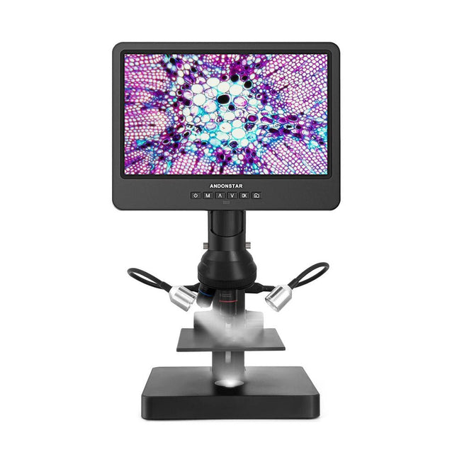
This versatile digital microscope covers a wide magnification range (18-720x, 1560-2040x, 2760-4080x) with 3 lenses for hobby, industrial and biologic purposes. Lens A (18-720x) can be used to observe whole coins or parts, circuit boards, plants, stones, etc. With lens B (1560-2040x) and C (2760-4080x) you can observe biological slides.
Specifications
Magnification
Lens A
18-720
Focus range
12-320 mm
Lens B
1560-2040
Focus range
7-8 mm
Lens C
2760-4080
Focus range
3-4 mm
Screen size
10 inch (25.7 cm)
Video resolution (max.)
UHD 2880x2160 (24fps)
Video format
MP4
Photo format
JPG
Photo resolution
5600x2400 (with interpolation)
Frame rate
Max. 120fps
HDMI output
Yes (only HDMI monitor displays)
PC output
Yes
Power supply
USB 5 V DC (not included)
Stand material
Pro Plastic
Stand size
20 x 19 x 30 cm
Included
1x Andonstar AD249S-P Digital Microscope
1x Pro plastic stand
1x Lens A (fixed)
1x Lens (B & C)
1x USB cable
1x HDMI cable
1x Remote control
1x Dimmer cable
3x Backdrop board
1x Slides kit
1x 32 GB microSD card
1x Observation box
1x Tweezers
1x Screw driver
1x User manual
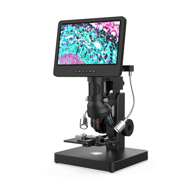
This versatile digital microscope covers a wide magnification range (18-720x, 1560-2040x, 2760-4080x, 3600-5100x, 60-240x) with 5 lenses for hobby, industrial and biologic purposes.
Lens A (18-720x) can be used to observe whole coins or parts, circuit boards, plants, stones, etc. With lens B (1560-2040x), C (2760-4080x) and M (3600-5100x) you can observe biological slides. Lens L is ideal for soldering and repair work.
In addition, the microscope has an endoscope for clear observation of the sides of components and inner tubes, allowing 360° viewing without blind spots.
Specifications
Magnification
Lens A
18-720x
Lens B
1560-2040x
Lens C
2760-4080x
Lens M
3600-5100x
Lens L
60-240x
Screen size
10 inch (25.7 cm)
Video resolution (max.)
UHD 2880x2160 (24fps)
Video format
MP4
Photo format
JPG
Photo resolution
5600x2400 (with interpolation)
Frame rate
Max. 120fps
HDMI output
Yes (only HDMI monitor displays)
PC output
Yes
Power supply
USB 5 V DC (not included)
Stand material
Metal
Stand size
20 x 19 x 40 cm
Included
1x Andonstar AD269S Digital Microscope
1x Metal stand with 2 LEDs
1x X-Y Moveable stage
1x Lens A
1x Lens set (B, C, M)
1x Lens L
1x Endoscope (+ accessories)
1x USB cable
1x HDMI cable
1x Remote control
1x Dimmer cable
3x Backdrop board
5x Biological slides
1x 32 GB microSD card
1x Observation box
1x Tweezers
1x Manual
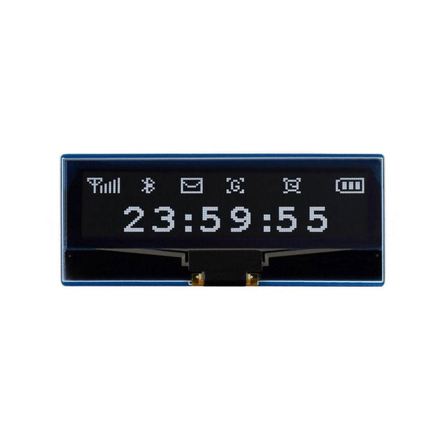
Features Adopts both 4-wire SPI and I²C interface, better compatibility, fast data rate Standard Raspberry Pi Pico header, supports Raspberry Pi Pico series boards Comes with development resources and manual (Raspberry Pi Pico C/C++ and MicroPython examples) Specifications Logical voltage 3.3 V Viewing angle >160° Operating voltage 3.3 V/5 V Resolution 128×32 pixels Communication interface 4-wire SPI, I²C Display size 55.02 × 13.10 mm Display panel OLED Pixel size 0.41 × 0.39 mm Driver SSD1305 Dimensions 63.00 × 26.00 mm
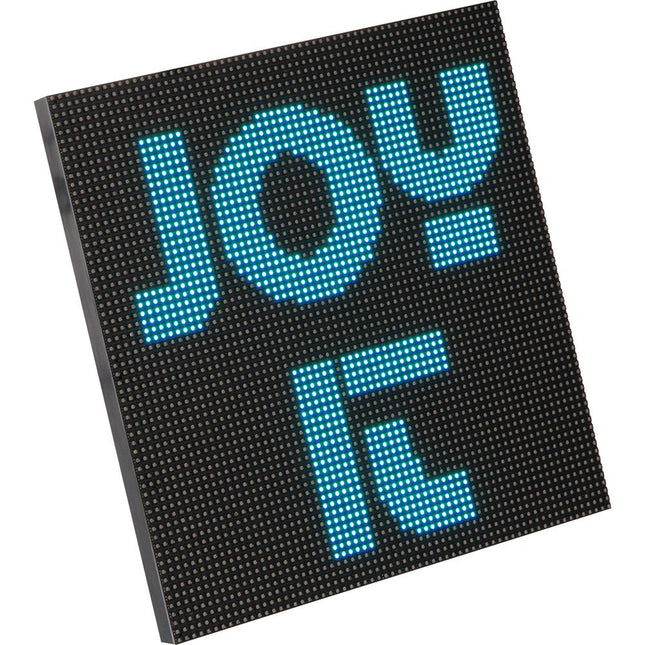
The RGB matrix module is equipped with 4096 LEDs and is characterized by a particularly small grid size of only 3mm. This makes it ideal for pictorial representations. Video sequences can also be displayed.
The module is supplied with the necessary cables. It is perfectly suited in combinations with single board computers like the Raspberry Pi, Arduino, BBC Microbit and many more.
Specifications
Display
RGB-LED
Resolution
64 x 64
Amount of LED
4096 LEDs
LED Size
3 mm Pitch
Supply Voltage
5 V
Max. Power Input
40 W
Control
1/32 Scan
Operating Temperature
-20~55°C
Viewing Angle
140°
Pixel Density
111111 Pixel/m²
Dimensions
192 x 192 x 14 mm
Weight
246 g
Items Shipped
LED-Matrix, Kabel
Downloads
Datasheet
Manual
The RP2040 contains two ARM Cortex-M0+ processors (up to 133 MHz) and features:
264 kB of embedded SRAM in six banks
6 dedicated IO for SPI Flash (supporting XIP)
30 multifunction GPIO:
Dedicated hardware for commonly used peripherals
Programmable IO for extended peripheral support
Four 12-bit ADC channels with internal temperature sensor (up to 0.5 MSa/s)
USB 1.1 Host/Device functionality
The RP2040 is supported with C/C++ and MicroPython cross-platform development environments, including easy access to runtime debugging. It has a UF2 boot and floating-point routines baked into the chip. While the chip has a large internal RAM, the board includes an additional 16 MB of external QSPI flash memory to store program code.
Features
Raspberry Pi Foundation's RP2040 microcontroller
16MB QSPI Flash Memory
JTAG PTH Pins
Thing Plus (or Feather) Form-Factor:
18x Multifunctional GPIO Pins
Four available 12-bit ADC channels with an internal temperature sensor (500 kSa/s)
Up to eight 2-channel PWM
Up to two UARTs
Up to two I²C buses
Up to two SPI buses
USB-C Connector:
USB 1.1 Host/Device functionality
2-pin JST Connector for a LiPo Battery (not included):
500 mA charging circuit
Qwiic Connector
Buttons:
Boot
Reset
LEDs:
PWR - Red 3.3 V power indicator
CHG - Yellow battery charging indicator
25 - Blue status/test LED (GPIO 25)
WS2812 - Addressable RGB LED (GPIO 08)
Four Mounting Holes:
4-40 screw compatible
Dimensions: 2.3' x 0.9'
RP2040 Features
Dual Cortex M0+ processors, up to 133 MHz
264 kB of embedded SRAM in 6 banks
6 dedicated IO for QSPI flash, supporting execute in place (XIP)
30 programmable IO for extended peripheral support
SWD interface
Timer with 4 alarms
Real-time counter (RTC)
USB 1.1 Host/Device functionality
Supported programming languages
MicroPython
C/C++
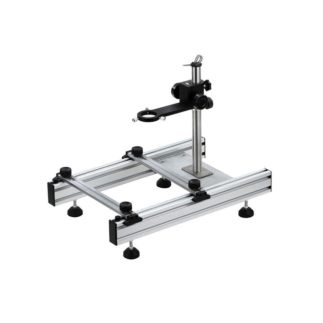
This multi-purpose tool offers an excellent all round solution, ideal for holding big size PCBs and desoldering work, etc.
Features
The arms of the repair station can move up and down conveniently, easy for operation.
The adjustable parts are made of the same material for microscope, with high quality, perfect stability and precision.
The rubber feet can move in all directions, ensuring the operation platform is always on a flat surface.
Suitable for desoldering BGA ICs.
Specifications
Rough adjusting range in height
0∼230 mm
Precise adjusting range in height
0∼60 mm
Max. holding size of PCB
250 mm (length or width)
Min. holding size of PCB
20 mm (length or width)
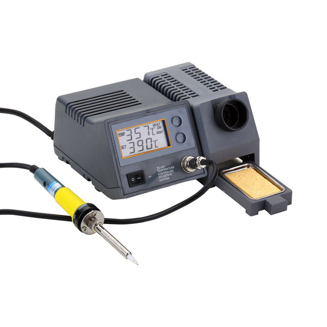
The powerful soldering station with LCD panel has been designed for a wide temperature range (from 150-450°C) and is ideal for general purpose soldering as well as specialized lead-free soldering applications. The soldering iron is controlled automatically by the microprocessor.
With its high-quality sensor the heat exchange system guarantees precise temperature control at the soldering tip. This digital temperature controlled soldering station includes a holder and cleaning sponge.
Specificaties
Operating voltage
220-240 V, 50 Hz
Power consumption
80 W
Soldering iron power
48 W
Operating voltage soldering iron
24 V
Temperature (adjustable)
150-450°C
Dimensions
195 x 87 x 165 mm
These high-precision, anti-static tweezers with black ESD coating can be used in electronics for placing SMD components when soldering and for repairing smartwatches, smartphones, tablets, PCs etc. It is ideal for picking up small components in hard to reach places.
Specifications
Length
115 mm
Width
9 mm
The M12 mount lens (12 MP, 2.7 mm) is ideal for use with the Raspberry Pi HQ Camera Module, offering sharp and detailed imaging for a wide range of applications.
Spencer is a DIY voice assistant that will teach you about AI, voice recognition, IoT, and speech synthesis.
Features
Ask about the weather forecast for your area
Hear a joke
Ask him to sing you a song
Set a stopwatch
Make Spencer display custom animations
Laugh at his corny popular culture references
Included
Spencer’s circuit board that includes a pre-soldered 144-pixel LED grid
The brain board – does smart stuff and includes a dual-core processor, a 16 MB flash memory chip, and power-management circuitry
Acrylic casing – this protects Spencer’s innards from the outside world
A big red button
Various smaller components such as resistors and pushbuttons
Micro USB cable for powering your Spencer
5W Speaker
Instruction booklet – ready for your offline knowledge consumption
Here you can find the assembly guide!
This is a kit for a pan-tilt mechanism explicitly designed for Pixy2. After assembling the kit and connecting it to Pixy2, you'll be able to follow colored objects using the Pan/Tilt demo.
It includes two laser-cut plastic pieces for the base, two different servos for the pan and tilt axes, and all the mounting hardware and cable ties you will need to assemble.
Features
The pan-tilt mechanism for Pixy2 is redesigned, making it smaller and faster than the pan-tilt for the original Pixy.
All necessary hardware is included.
The pan-tilt base is attached directly to an Arduino with Arduino-compatible hole-pattern and includes stand-offs and fasteners.
Several pan-tilt demos are provided that can run using either Arduino, Raspberry Pi or stand-alone (no controller).
Downloads
Manual
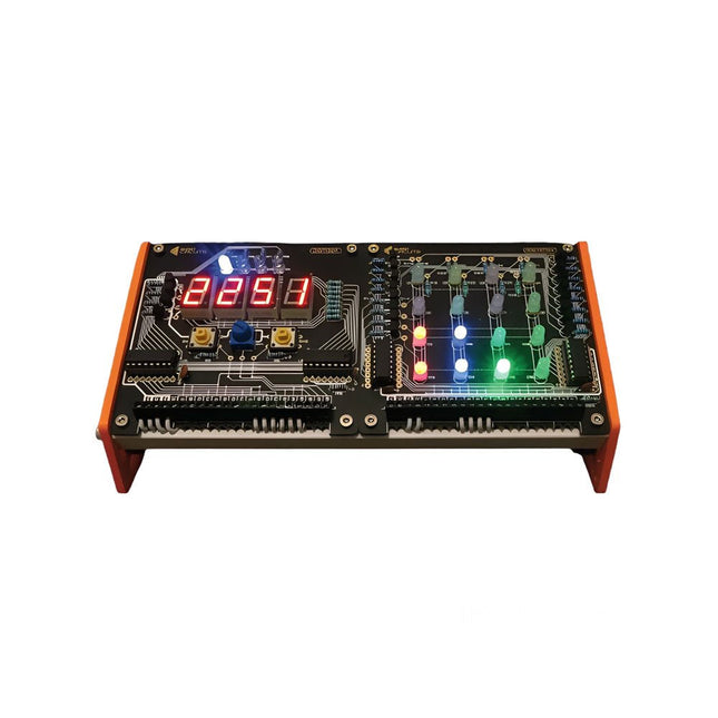
Get started with microcontroller based electronics
This Arduino-compatible bundle contains the Motherboard, Digitiser, Sensor Array and RGB Matrix. With these 4 boards you have everything you need to build a clock, score counter, timer, task reminder, thermometer, humidity display, sound meter, light meter, clap trigger, colored bar graph display, animated alarm, and much more!
The Motherboard has a built in real time clock module that keeps time even when unplugged.
The Digitiser can display 4 digits or characters and includes 2 buttons and a potentiometer to let you control what’s being displayed, or the brightness of the display.
The Sensor Array can read temperature, relative humidity, sound and light, with an SD card slot for data recording.
The RGB Matrix has 16 RGB LEDs that are controlled through shift registers, so only use 3 or 4 pins of the Motherboard.
Motherboard
The Motherboard is an Arduino-compatible microcontroller breakout board designed around the ATmega328P. The board comes in a solder-it-yourself kit with all the components you need to get started with microcontroller based electronics. All other boards connect to this.
Based on the ATmega328P
Arduino compatible
On-Board RTC (Real Time Clock)
FTDI Header for easy programming
Bluetooth Header
Terminal Block Connections
Digitiser
The Digitiser is a versatile display and input board. It let’s you visualise your data. Show your sensor information, clock digits, or even keep score for your favourite card game. The Digitiser also includes some buttons and a knob to let you take control.
4x 7-Segment Displays
Uses 595 Shift Registers
2 Switches and a Potentiometer
4 colored 'Mode' LEDs
Chainable with other 595 Boards
Terminal Block Connections
Sensor Array
As the name suggests, the Sensor Array is an array of sensors. Measure temperature and relative humidity via the DHT11, light via the light dependant resistor, and sound via the microphone and amplifier circuit. Then you can log the data using the on-board SD card slot.
DHT11 Temp & Humidity Sensor
Microphone and Amplifier Circuit
Light Dependent Resistor
MicroSD Slot for Saving Data
Logic Level Converter Circuit
Terminal Block Connections
RGB Matrix
Add color to your project by controlling 16 red, 16 green and 16 blue LEDs with just 3 pins of your microcontroller. The RGB Matrix uses shift registers, a matrix and switching transistors, so there’s plenty to learn and explore.
4x4 (16) RGB LEDs
Uses 595 Shift Registers
Chainable with other 595 Boards
Transistor Switches
Terminal Block Connections
Downloads (Manuals)
Motherboard
Digitiser
Sensor Array
RGB Matrix
As always with Arduino, every element of the platform – hardware, software, and documentation – is freely available and open-source. This means you can learn exactly how it's made and use its design as the starting point for your own circuits. Hundreds of thousands of Arduino Boards are already fueling people’s creativity all over the world, every day. The Arduino Ethernet Shield 2 allows an Arduino Board to connect to the internet. It is based on the Wiznet W5500 Ethernet chip. The Wiznet W5500 provides a network (IP) stack capable of both TCP and UDP. It supports up to eight simultaneous socket connections. Use the Ethernet library to write sketches that connect to the Internet using the Shield. The Ethernet Shield 2 connects to an Arduino Board using long wire-wrap headers extending through the Shield. This keeps the pin layout intact and allows another Shield to be stacked on top of it. The most recent revision of the board exposes the 1.0 pinout on rev 3 of the Arduino UNO Board. The Ethernet Shield 2 has a standard RJ-45 connection, with an integrated line transformer and Power over Ethernet enabled. There is an onboard micro-SD card slot, which can be used to store files for serving over the network. It is compatible with the Arduino Uno and Mega (using the Ethernet library). The onboard micro-SD card reader is accessible through the SD Library. When working with this library, SS is on Pin 4. The original revision of the Shield contained a full-size SD card slot; this is not supported. The Shield also includes a reset controller, to ensure that the W5500 Ethernet module is properly reset on power-up. Previous revisions of the Shield were not compatible with the Mega and needed to be manually reset after power-up.
SwiftIO offers a full Swift compiler and framework environment that runs on the microcontroller. The SwiftIO board is a compact electronic circuit board that runs Swift on the bare metal, giving you a system that can be used to control all kinds of electronic projects.
Features
NXP i.MX RT1052 Crossover Processor with ARM Cortex-M7 core @ 600 MHz
8 MB SPI Flash, 32 MB SDRAM
On-board DAPLink debugger
On-board USB to UART for serial communication
On-board RGB LED
On-board SD socket
46x GPIO, 12x ADC, 14x PWM, 4x UART, 2x I²C, 2x SPI etc.
Many additional advanced features to meet the needs of advanced users
Zephyr RTOS support
MadMachine IDE is the premier integrated development environment for SwiftIO, which makes it easy to write Swift code and download it to the board.
Celebrating the Arduino Uno with a miniaturized limited edition
The world's favorite development board has gone mini. Everything in this version of the Arduino Uno is unique. Black and gold, finishing, elegant design and packaging, all delivered to the highest standard. A little jewel to celebrate the Arduino community and what we’ve been doing together for all these years.
Each item is unique and numbered on the PCB, and includes a hand-signed letter from the founders. It’s a limited edition, so get while it’s in stock!
For serious Arduino Uno lovers
Arduino Uno Mini Limited Edition is a collector’s item for serious Arduino Lovers: hobbyists, students, makers, reimaginers, dreamers, hopers, fans, engineers, designers, questioners, cake-makers, problem-solvers, puzzlers, gamers, debaters, developers, entrepreneurs, architects, future-shapers, musicians, scientists... 10 million projects based on (official) Uno boards that have contributed to this incredible story.
Specifications
The Arduino Uno Mini Limited Edition is a microcontroller board based on the ATmega328P. It has 14 digital inputs/outputs (six of which can be used as PWM outputs), six analog inputs, a 16 MHz ceramic resonator, a USB-C connector, and a reset button. Contains everything needed to support the microcontroller. Simply connect it to a computer with a USB cable, use a power adapter, or connect a battery to get started.
Microcontroller
ATmega328P
USB connector
USB-C
Built-in LED Pins
13
Digital I/O Pins
14
Analog Input Pins
6
PWM Pins
6
UART
Yes
I²C
Yes
SPI
Yes
Circuit operating voltage
5 V
Input Voltage (limit)
6-12 V
Battery connector
None
DC current per I/O Pin
20 mA
DC current for 3.3 V Pin
50 mA
Main processor
ATmega328P (16 MHz)
USB-serial processor
ATmega16U2 (16 MHz)
Memory ATmega328P
2 KB SRAM, 32 KB Flash, 1 KB EEPROM
Weight
8.05 g
Dimensions
26.70 x 34.20 mm
Downloads
Datasheet
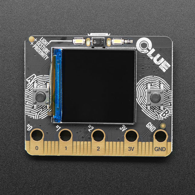
Features
Nordic nRF52840 Bluetooth LE processor – 1 MB of Flash, 256KB RAM, 64 MHz Cortex M4 processor
1.3″ 240×240 Color IPS TFT display for high-resolution text and graphics
Power it from any 3-6V battery source (internal regulator and protection diodes)
Two A / B user buttons and one reset button
ST Micro series 9-DoF motion – LSM6DS33 Accel/Gyro + LIS3MDL magnetometer
APDS9960 Proximity, Light, Color, and Gesture Sensor
PDM Microphone sound sensor
SHT Humidity
BMP280 temperature and barometric pressure/altitude
RGB NeoPixel indicator LED
2 MB internal flash storage for datalogging, images, fonts or CircuitPython code
Buzzer/speaker for playing tones and beeps
Two bright white LEDs in front for illumination / color sensing
Qwiic / STEMMA QT connector for adding more sensors, motor controllers, or displays over I²C. You can plug in GROVE I²C sensors by using an adapter cable.
Programmable with Arduino IDE or CircuitPython
The Raspberry Pi 500 (based on the Raspberry Pi 5) features a quad-core 64-bit Arm processor, RP1 I/O controller, 8 GB RAM, wireless networking, dual-display output, 4K video playback, and a 40-pin GPIO header. It's a powerful, compact all-in-one computer built into a portable keyboard.
The built-in aluminum heatsink provides improved thermal performance, allowing the Raspberry Pi 500 to run quickly and smoothly even under heavy load.
Specifications
SoC
Broadcom BCM2712
CPU
ARM Cortex-A76 (ARM v8) 64-bit
Clock rate
4x 2.4 GHz
GPU
VideoCore VII (800 MHz)
RAM
8 GB LPDDR4X (4267 MHz)
WiFi
IEEE 802.11b/g/n/ac (2.4 GHz/5 GHz)
Bluetooth
Bluetooth 5.0, BLE
Ethernet
Gigabit Ethernet (with PoE+ support)
USB
2x USB-A 3.0 (5 GBit/s)1x USB-A 2.01x USB-C (for power supply)
PCI Express
1x PCIe 2.0
GPIO
Standard 40-pin GPIO header
Video
2x micro-HDMI ports (4K60)
Multimedia
H.265 (4K60 decode)OpenGL ES 3.1, Vulkan 1.2
SD card
microSD
Power supply
5 V DC (via USB-C)
Keyboard layout
US (QWERTY)
Dimensions
286 x 122 x 23 mm
Downloads
Datasheet
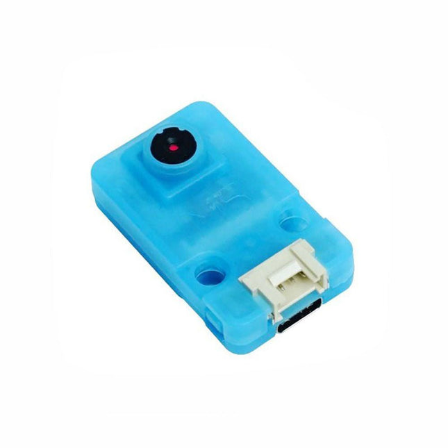
OV7740 is a AI Camera powered by Kendryte K210, an edge computing system-on-chip(SoC) with a dual-core 64bit RISC-V CPU and state-of-art neural network processor.
Features
Dual-Core 64-bit RISC-V RV64IMAFDC (RV64GC) CPU / 400Mhz(Normal)
Dual Independent Double Precision FPU
8MiB 64bit width On-Chip SRAM
Neural Network Processor(KPU) / 0.8Tops
Field-Programmable IO Array (FPIOA)
AES, SHA256 Accelerator
Direct Memory Access Controller (DMAC)
Micropython Support
Firmware encryption support
On-board Hardware:
Flash: 16M Camera :OV7740
2x Buttons
Status Indicator LED
External storage: TF card/Micro SD
Interface: HY2.0/compatible GROVE
Applications
Face recognition/detection
Object detection/classification
Obtain the size and coordinates of the target in real-time
Obtain the type of detected target in real-time
Shape recognition Video recorder
Included
1x UNIT-V(include 20cm 4P cable and USB-C cable)
The GTMEDIA V8 Finder2 is a handheld satellite meter that supports DVB-S/S2 and MPEG-2/4 H.264 (8-bit) standards. Designed for convenience, it boasts a compact size, lightweight build, user-friendly interface, extended battery life, and a comprehensive set of features.
This meter provides all the essential functions needed for efficient installation and verification of digital satellite TV services, whether for individual residences or multi-dwelling units.
Specifications
Frequency Range
950-2150 MHz
DC IN
13 V/18 V (max 350 mA)
Display
3.5" HD TFT LCD Screen (320 x 240)
Standard
DVB-S/S2/S2X
Battery
Built-in 7.4 V/4000 mAh Lithium battery
Dimensions
95 x 155 x 45 mm
Weight
450 g
Included
GTmedia V8 Finder 2
USB cable
Manual
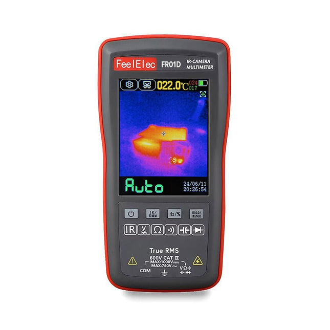
The FR01D (2-in-1) thermal imaging camera and multimeter is a compact and lightweight solution that simplifies diagnostic and maintenance tasks. The one-click function allows you to switch effortlessly between thermal imaging and multimeter mode, giving you two important tools in one portable device.
The multimeter is capable of measuring DC and AC voltage, resistance, diode checks, continuity testing, and capacitance.
The FR01D has a 2.8-inch touchscreen with a resolution of 320 x 480 pixels. The device is powered by an integrated rechargeable lithium battery and can be charged via USB.
With the FR01D, you can inspect and maintain circuit boards, check power supplies, repair electronic devices, and overhaul household appliances. Its compact size, multifunctionality, and user-friendliness make the FR01D the ideal companion for electronics and maintenance technicians.
General Specifications
Display size
2.8" (320 x 480)
Touchscreen
Resistive
Data transmission
USB-C
Image storage format
BMP
Battery
Li-ion battery
Storage temperature
−20°C~60°C(−4°F~140°F)
Operating temperature
0°C~50°C(32°F~122°F)
Operating humidity
<85% RH
Dimensions
134 x 69 x 25 mm
Weight
130 g
Thermal Imaging Specifications
Sensor
Vanadium oxide (VOx)
Image capture frequency
25 Hz
Thermal imaging pixels
192 x 192
Field of View (FOV)
50.0°(H) x 50°(V) / 72.1°(D)
Temperature range
−20°C ~ +550°C (−4°F~1022°F)
Gain mode
Auto
Accuracy
±2°C or ±2%
Measurement resolution
0.1°C / 0.1°F
Multimeter Specifications
DC input voltage (max.)
1000 V
AC input voltage (max.)
750 V
Resistance (max.)
99.99 MΩ
Capacitance (max.)
99.99 mF
Duty cycle test range
0.1% ~ 99.9%
Diode test range
0 V ~ 3 V
Continuity test
999.9 Ω
Display
9999 counts (Refreshes 3x per second)
Accuracy
Function
Range
Resolution
Accuracy
AC Voltage
400 mV
0.1 mV
2% +3
9.999 V
0.001 V
1.0% +3
99.99 V
0.01 V
999.9 V
0.1V
DC Voltage
400 mV
0.1 mV
2% +3
9.999 V
0.001 V
1.0% +3
99.99 V
0.01 V
999.9 V
0.1 V
Resistance
999.9 Ω
0.1 Ω
0.5% +3
9.999 KΩ
0.001 kΩ
99.99 KΩ
0.01 kΩ
999.9 KΩ
0.1 kΩ
9.999 MΩ
0.001 MΩ
99.99 MΩ
0.01 MΩ
1.5% +3
Diode Test
3.000 V
0.001 V
10%
Capacitance
9.999 nF
0.001 nF
2% +5
99.99 nF
0.01 nF
999.9 nF
0.1 nF
9.999 uF
0.001 uF
99.99 uF
0.01 uF
999.9 uF
0.1 uF
9.999 mF
0.001 mF
5% +5
99.99 mF
0.01 mF
Included
1x FR01D IR-Camera and Multimeter
2x Test Leads
1x USB Cable
1x Manual
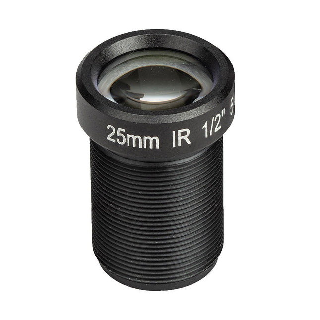
The M12 Mount Lens (5 MP, 25 mm) is ideal for use with the Raspberry Pi HQ Camera Module, offering sharp and detailed imaging for a wide range of applications.
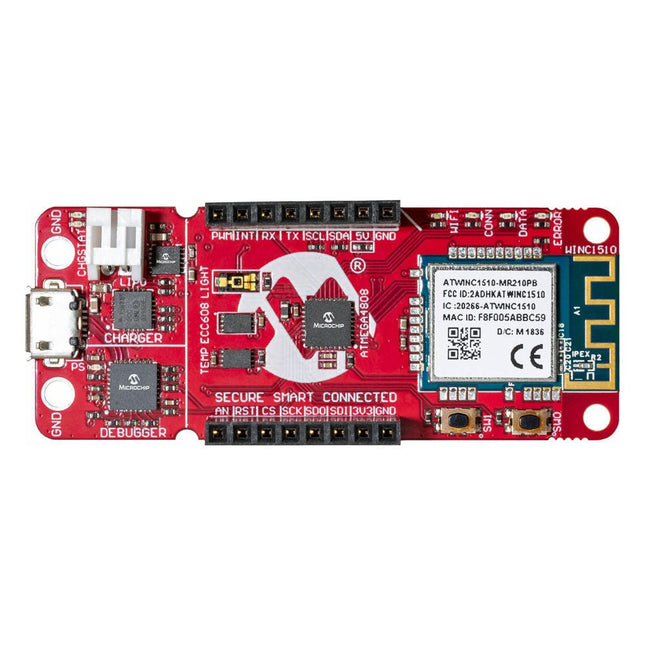
The AVR-IoT WA development board combines a powerful ATmega4808 AVR MCU, an ATECC608A CryptoAuthentication secure element IC and the fully certified ATWINC1510 Wi-Fi network controller – which provides the most simple and effective way to connect your embedded application to Amazon Web Services (AWS). The board also includes an on-board debugger, and requires no external hardware to program and debug the MCU.
Out of the box, the MCU comes preloaded with a firmware image that enables you to quickly connect and send data to the AWS platform using the on-board temperature and light sensors. Once you are ready to build your own custom design, you can easily generate code using the free software libraries in Atmel START or MPLAB Code Configurator (MCC).
The AVR-IoT WA board is supported by two award-winning Integrated Development Environments (IDEs) – Atmel Studio and Microchip MPLAB X IDE – giving you the freedom to innovate with your environment of choice.
Features
ATmega4808 microcontroller
Four user LED’s
Two mechanical buttons
mikroBUS header footprint
TEMT6000 Light sensor
MCP9808 Temperature sensor
ATECC608A CryptoAuthentication™ device
WINC1510 WiFi Module
On-board Debugger
Auto-ID for board identification in Atmel Studio and Microchip MPLAB X
One green board power and status LED
Programming and debugging
Virtual COM port (CDC)
Two DGI GPIO lines
USB and battery powered
Integrated Li-Ion/LiPo battery charger
The FNIRSI DSO153 is a highly practical and cost-effective handheld oscilloscope with a real-time sampling rate of 5 MSa/s, 1 MHz bandwidth, and complete triggering function (single, normal, auto). It can be used freely for both periodic analog signals and non-periodic digital signals, and can measure up to ±400 V voltage with an efficient one-click AUTO, which can display the measured waveform without complicated adjustments. Additionally, it features a function signal generator capable of outputting 14 types of signals (10 KHz).
Equipped with a 2.8-inch 320x240 resolution HD LCD screen and a built-in 1000 mAh high-quality lithium battery, it can be used for about 4 hours when fully charged.
Features
2.8-inch HD LCD display with 320x240 Resolution
Portable Pocket Oscilloscope with Signal Generator
Lightweight, mini-sized, assembled
Faster sampling: 5 MS/s, 1 MHz bandwidth
Versatile triggering: Single, Normal, Auto
User-friendly: One-button setup
Extended battery: 1000 mAh, 4 hours
Multi-functionality: 10 KHz Sine Wave Generator
Specifications
Bandwidth
1 MHz
Sampling rate
5 MSa/s
Vertical Sensitivity
10mV/Div – 20V/Div
Time Base Range
500ns/Div – 20s/Div
Voltage Range
X1: ±40 V (Vpp: 80 V)X10: ±400 V (Vpp: 800 V)
Trigger Method
Auto / Normal / Single
Coupling Method
AC/DC
Frequency Range
0-10 KHz
Duty Cycle Range
0-100%
Amplitude Range
0.1-3.3 V
Display
2.8 inches (Resolution: 320 x 240)
USB Charging
5 V/1 A
Lithium Battery Capacity
1000 mAh
Dimensions
99 x 68.3 x 19.5 mm
Weight
100 g
Included
1x FNIRSI DSO153 Oscilloscope
1x P6100 oscilloscope probe
1x Adapter
1x Alligator clip probe
1x USB charging cable
1x Lanyard
1x Manual
Downloads
Manual
Firmware V1.1.8