Clearance Sale %
-
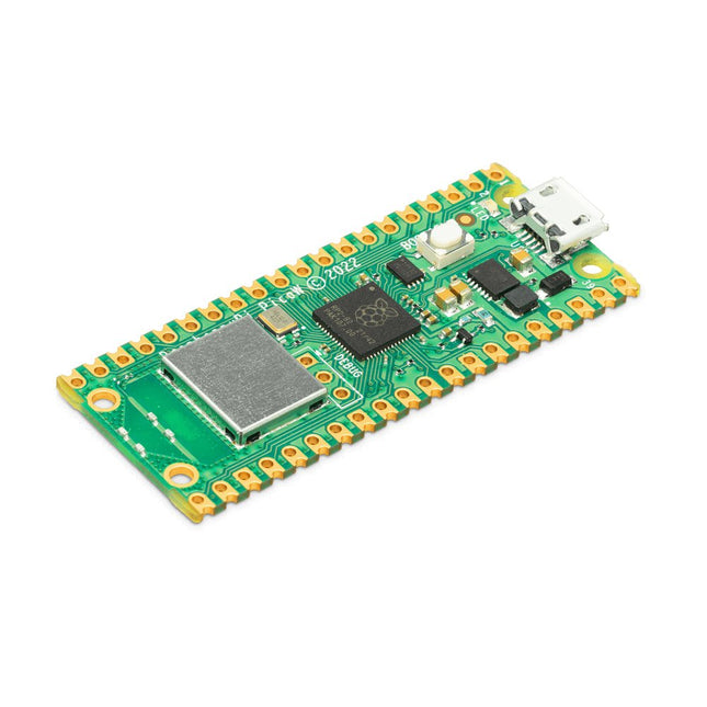
Raspberry Pi Foundation Raspberry Pi Pico W
Raspberry Pi Pico W is a microcontroller board based on the Raspberry Pi RP2040 microcontroller chip. The RP2040 microcontroller chip ('Raspberry Silicon') offers a dual-core ARM Cortex-M0+ processor (133 MHz), 256 KB RAM, 30 GPIO pins, and many other interface options. In addition, there is 2 MB of on-board QSPI flash memory for code and data storage. Raspberry Pi Pico W has been designed to be a low cost yet flexible development platform for RP2040 with a 2.4 GHz wireless interface using an Infineon CYW43439. The wireless interface is connected via SPI to the RP2040. Features of Pico W RP2040 microcontroller with 2 MB of flash memory On-board single-band 2.4 GHz wireless interfaces (802.11n) Micro USB B port for power and data (and for reprogramming the flash) 40 pin 21 x 51 mm 'DIP' style 1 mm thick PCB with 0.1' through-hole pins also with edge castellations Exposes 26 multi-function 3.3 V general purpose I/O (GPIO) 23 GPIO are digital-only, with three also being ADC capable Can be surface mounted as a module 3-pin ARM serial wire debug (SWD) port Simple yet highly flexible power supply architecture Various options for easily powering the unit from micro USB, external supplies or batteries High quality, low cost, high availability Comprehensive SDK, software examples and documentation Features of the RP2040 microcontroller Dual-core cortex M0+ at up to 133 MHz On-chip PLL allows variable core frequency 264 kByte multi-bank high performance SRAM External Quad-SPI Flash with eXecute In Place (XIP) and 16 kByte on-chip cache High performance full-crossbar bus fabric On-board USB1.1 (device or host) 30 multi-function general purpose I/O (four can be used for ADC) 1.8-3.3 V I/O voltage 12-bit 500 ksps analogue to digital converter (ADC) Various digital peripherals 2x UART, 2x I²C, 2x SPI, 16x PWM channels 1x timer with 4 alarms, 1x real time clock 2x programmable I/O (PIO) blocks, 8 state machines in total Flexible, user-programmable high-speed I/O Can emulate interfaces such as SD card and VGA Note: Raspberry Pi Pico W I/O voltage is fixed at 3.3 V. Downloads Datasheet Specifications of 3-pin Debug Connector
€ 7,95€ 3,95
Members identical
-
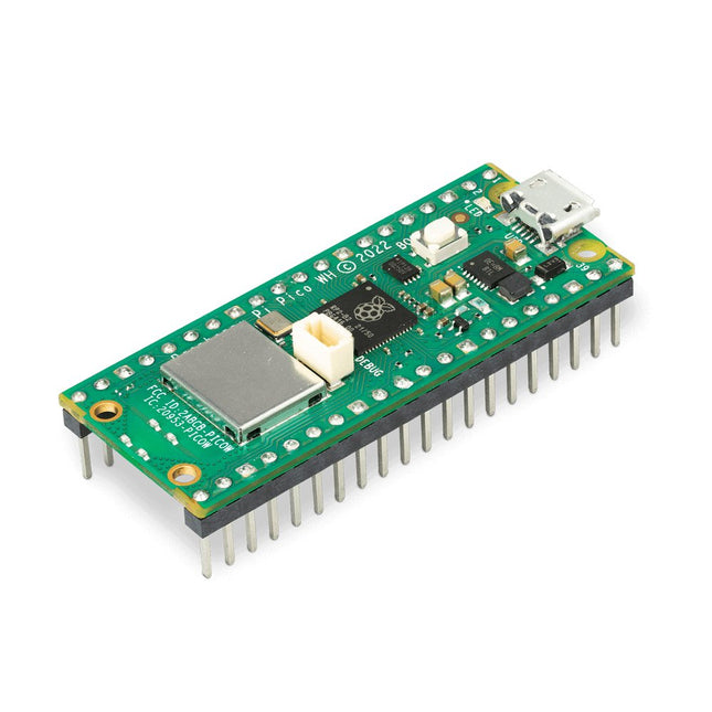
Raspberry Pi Foundation Raspberry Pi Pico WH
Raspberry Pi Pico WH is a microcontroller board based on the Raspberry Pi RP2040 microcontroller chip. The RP2040 microcontroller chip ('Raspberry Silicon') offers a dual-core ARM Cortex-M0+ processor (133 MHz), 256 KB RAM, 30 GPIO pins, and many other interface options. In addition, there is 2 MB of on-board QSPI flash memory for code and data storage. Raspberry Pi Pico WH has been designed to be a low cost yet flexible development platform for RP2040 with a 2.4 GHz wireless interface using an Infineon CYW43439. The wireless interface is connected via SPI to the RP2040. Features of Pico WH RP2040 microcontroller with 2 MB of flash memory On-board single-band 2.4 GHz wireless interfaces (802.11n) Micro USB B port for power and data (and for reprogramming the flash) 40 pin 21 x 51 mm 'DIP' style 1 mm thick PCB with 0.1' through-hole pins also with edge castellations Exposes 26 multi-function 3.3 V general purpose I/O (GPIO) 23 GPIO are digital-only, with three also being ADC capable Can be surface mounted as a module 3-pin ARM serial wire debug (SWD) port Simple yet highly flexible power supply architecture Various options for easily powering the unit from micro USB, external supplies or batteries High quality, low cost, high availability Comprehensive SDK, software examples and documentation Pre-populated headers and 3-pin debug connector Features of the RP2040 microcontroller Dual-core cortex M0+ at up to 133 MHz On-chip PLL allows variable core frequency 264 kByte multi-bank high performance SRAM External Quad-SPI Flash with eXecute In Place (XIP) and 16 kByte on-chip cache High performance full-crossbar bus fabric On-board USB1.1 (device or host) 30 multi-function general purpose I/O (four can be used for ADC) 1.8-3.3 V I/O voltage 12-bit 500 ksps analogue to digital converter (ADC) Various digital peripherals 2x UART, 2x I²C, 2x SPI, 16x PWM channels 1x timer with 4 alarms, 1x real time clock 2x programmable I/O (PIO) blocks, 8 state machines in total Flexible, user-programmable high-speed I/O Can emulate interfaces such as SD card and VGA Note: Raspberry Pi Pico W I/O voltage is fixed at 3.3 V. Downloads Datasheet Specifications of 3-pin Debug Connector
€ 9,95€ 4,95
Members identical
-
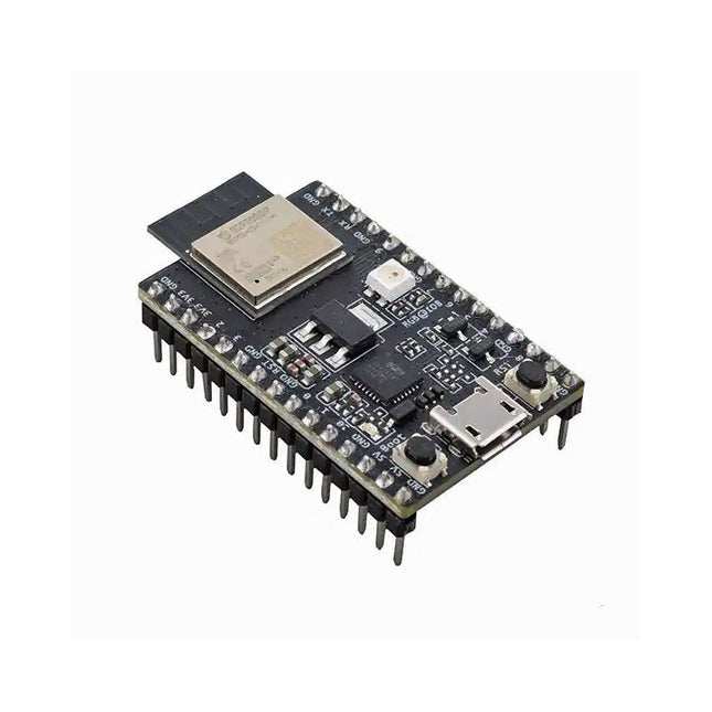
Espressif ESP32-C3-DevKitM-1
ESP32-C3-DevKitM-1 is an entry-level development board based on ESP32-C3-MINI-1, a module named for its small size. This board integrates complete Wi-Fi and Bluetooth LE functions. Most of the I/O pins on the ESP32-C3-MINI-1 module are broken out to the pin headers on both sides of this board for easy interfacing. Developers can either connect peripherals with jumper wires or mount ESP32-C3-DevKitM-1 on a breadboard. Specifications ESP32-C3-MINI-1 ESP32-C3-MINI-1 is a general-purpose Wi-Fi and Bluetooth LE combo module that comes with a PCB antenna. At the core of this module is ESP32-C3FN4, a chip that has an embedded flash of 4 MB. Since flash is packaged in the ESP32-C3FN4 chip, rather than integrated into the module, ESP32-C3-MINI-1 has a smaller package size. 5 V to 3.3 V LDO Power regulator that converts a 5 V supply into a 3.3 V output. 5 V Power On LED Turns on when the USB power is connected to the board. Pin Headers All available GPIO pins (except for the SPI bus for flash) are broken out to the pin headers on the board. For details, please see Header Block. Boot Button Download button. Holding down Boot and then pressing Reset initiates Firmware Download mode for downloading firmware through the serial port. Micro-USB Port USB interface. Power supply for the board as well as the communication interface between a computer and the ESP32-C3FN4 chip. Reset Button Press this button to restart the system. USB-to-UART Bridge Single USB-UART bridge chip provides transfer rates up to 3 Mbps. RGB LED Addressable RGB LED, driven by GPIO 8. Downloads ESP32-C3 Datasheet ESP32-C3-MINI-1 Datasheet ESP32-C3-DevKitM-1 Schematic ESP32-C3-DevKitM-1 PCB Layout ESP32-C3-DevKitM-1 Dimensions
€ 19,95€ 9,95
Members identical
-
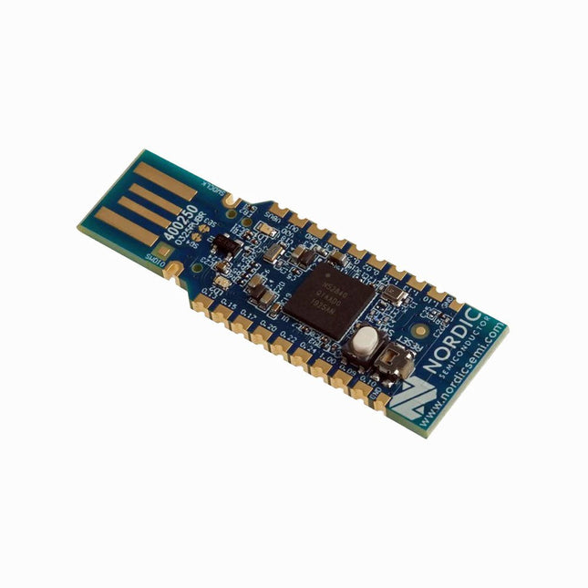
Nordic Semiconductor Nordic Semiconductor nRF52840 USB Dongle
The nRF52840 dongle is a small, low-cost USB dongle that supports Bluetooth 5.3, Bluetooth mesh, Thread, ZigBee, 802.15.4, ANT and 2.4 GHz proprietary protocols. The dongle is the perfect target hardware for use with nRF Connect for Desktop as it is low-cost but still support all the short range wireless standards used with Nordic devices. The dongle has been designed to be used as a wireless HW device together with nRF Connect for Desktop. For other use cases please do note that there is no debug support on the dongle, only support for programming the device and communicating through USB. It is supported by most of the nRF Connect for Desktop apps and will automatically be programmed if needed. In addition custom applications can be compiled and downloaded to the dongle. It has a user programmable RGB LED, a green LED, a user programmable button as well as 15 GPIO accessible from castellated solder points along the edge. Example applications are available in the nRF5 SDK under the board name PCA10059. The nRF52840 dongle is supported by nRF Connect for Desktop as well as programming through nRFUtil. Features Bluetooth 5.2 ready multiprotocol radio 2 Mbps Long Range Advertising Extensions Channel Selection Algorithm #2 (CSA #2) IEEE 802.15.4 radio support Thread ZigBee Arm Cortex-M4 with floating point support DSP instruction set ARM CryptoCell CC310 cryptographic accelerator 15 GPIO available via edge castellation USB interface direct to nRF52840 SoC Integrated 2.4 GHz PCB antenna 1 user-programmable button 1 user-programmable RGB LED 1 user-programmable LED 1.7-5.5 V operation from USB or external Downloads Datasheet Hardware Files
€ 19,95€ 9,95
Members identical
-
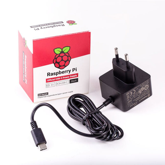
Raspberry Pi Foundation Official EU Power Supply for Raspberry Pi 4 (black)
The Raspberry Pi USB-C power supply is designed specifically to power the Raspberry Pi 4. The power supply features a USB-C cable and is available in four different models to suit different international power sockets, and in two colors. Specifications Output Output voltage +5.1 V DC Minimum load current 0 A Nominal load current 3.0 A Maximum power 15.3 W Load regulation ±5% Line regulation ±2% Ripple & noise 120 mVp-p Rise time 100 ms maximum to regulation limits for DC outputs Turn-on delay 3000 ms maximum at nominal input AC voltage and full load Protection Short circuit protectionOvercurrent protectionOver temperature protection Efficiency 81% minimum (output current from 100%, 75%, 50%, 25%)72% minimum at 10% load Output cable 1.5 m 18AWG Output connector USB-C Input Voltage range 100-240 V AC (rated)96-264 V AC (operating) Frequency 50/60 Hz ±3 Hz Current 0.5 A maximum Power consumption (no load) 0.075 W maximum Inrush current No damage shall occur, and the input fuse shall not blow Operating ambient temperature 0-40°C
€ 9,95€ 4,95
Members identical
-
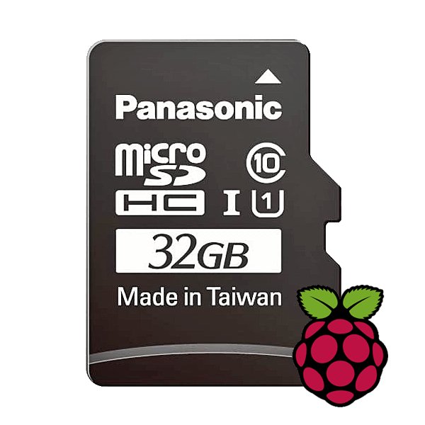
Raspberry Pi Foundation microSD Card pre-installed with Raspberry Pi OS (32 GB)
With this microSD (32 GB) with pre-installed Raspberry Pi OS you can start using your Raspberry Pi right away. Just plug it in and get started!
€ 10,95€ 5,50
Members identical
-

Raspberry Pi Foundation Official HDMI Cable for Raspberry Pi (black, 1 m)
The official Raspberry Pi micro HDMI to HDMI (A/M) cable (black, 1 m) designed for the Raspberry Pi 4 and 5. 19-pin HDMI Type D(M) to 19-pin HDMI Type A(M) 1 m cable (black) Nickel-plated plugs 4Kp60 compliant RoHS compliant 3 Mohm 300 VDC insulation, withstands 300 VDC for 0.1s
€ 6,95€ 3,50
Members identical
-
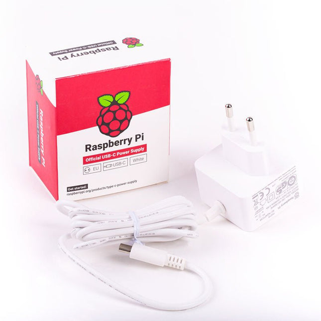
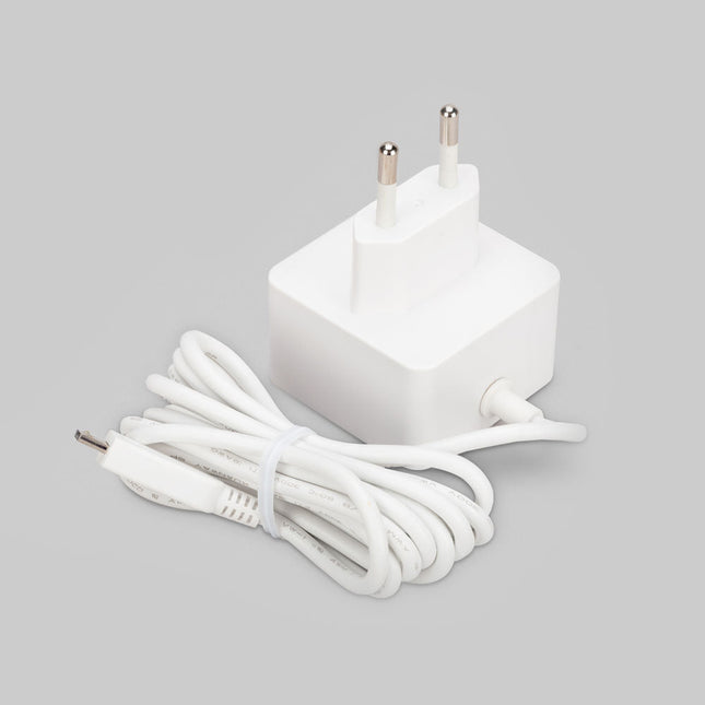
Raspberry Pi Foundation Official EU Power Supply for Raspberry Pi 4 (white)
The Raspberry Pi USB-C power supply is designed specifically to power the Raspberry Pi 4. The power supply features a USB-C cable and is available in four different models to suit different international power sockets, and in two colors. Specifications Output Output voltage +5.1 V DC Minimum load current 0 A Nominal load current 3.0 A Maximum power 15.3 W Load regulation ±5% Line regulation ±2% Ripple & noise 120 mVp-p Rise time 100 ms maximum to regulation limits for DC outputs Turn-on delay 3000 ms maximum at nominal input AC voltage and full load Protection Short circuit protectionOvercurrent protectionOver temperature protection Efficiency 81% minimum (output current from 100%, 75%, 50%, 25%)72% minimum at 10% load Output cable 1.5 m 18AWG Output connector USB-C Input Voltage range 100-240 V AC (rated)96-264 V AC (operating) Frequency 50/60 Hz ±3 Hz Current 0.5 A maximum Power consumption (no load) 0.075 W maximum Inrush current No damage shall occur, and the input fuse shall not blow Operating ambient temperature 0-40°C
€ 9,95€ 4,95
Members identical
-
Elektor Classics The Complete Linear Audio Library (USB Stick)
Jan Didden created Linear Audio in 2010 and published 14 Volumes between 2010 and 2017. Each 200-page Volume contains on average 10 articles by expert authors in the field of audio, acoustics, and instrumentation. Whether you are interested in tube amplifiers, solid-state equipment, loudspeaker design, capacitor and resistor distortion or distortion measurement, you are certain to find helpful advice and interesting discussions. From beginner to advanced level, for the audio professional or the serious hobbyist, this ExpertCollection will advance your understanding and offer new perspectives on common issues. Bonus material included with this collection is a 5-part YouTube series on negative feedback as applied to audio by renowned author Jan Didden, and nine additional landmark audio articles and presentations. If you are seriously interested in audio, acoustics, and instrumentation, you can’t afford to miss this! The published material is indexed and fully searchable and will provide an almost limitless resource for many years to come. You can read about Linear Audio’s authors, and the Table of Contents of each Volume, at linearaudio.net.
€ 149,95€ 74,95
Members identical
-
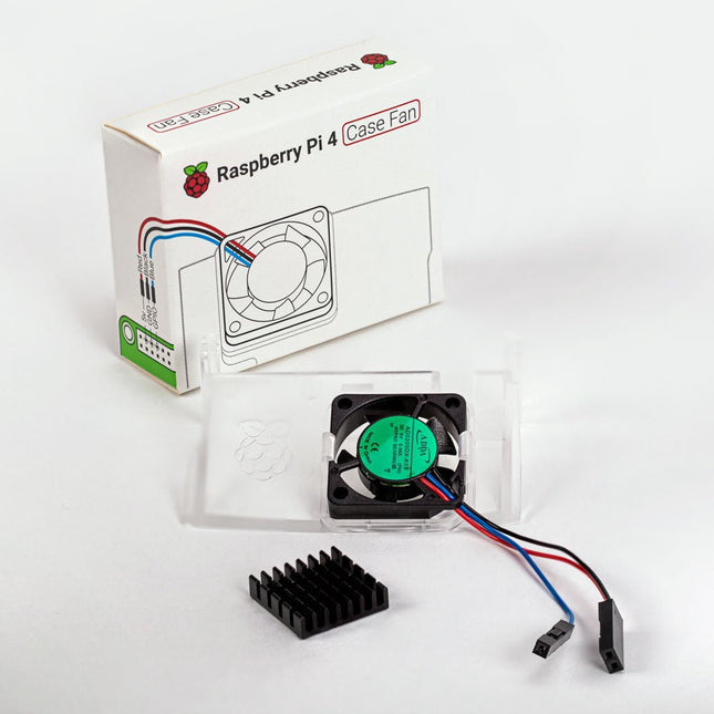
Raspberry Pi Foundation Raspberry Pi 4 Case Fan
Designed for overclockers and other power users, this fan keeps your Raspberry Pi 4 at a comfortable operating temperature even under heavy load. The temperature-controlled fan delivers up to 1.4 CFM of airflow over the processor, memory, and power management IC. The bundled heatsink (18 x 8 x 10 mm) with self-adhesive pad improves heat transfer from the processor. The Raspberry Pi 4 Case Fan works with Raspberry Pi 4 and the official Raspberry Pi 4 case.
€ 6,95€ 3,50
Members identical
-

Raspberry Pi Foundation Official HDMI Cable for Raspberry Pi (white, 1 m)
The official Raspberry Pi micro HDMI to HDMI (A/M) cable designed for the Raspberry Pi 4 and 5. 19-pin HDMI Type D(M) to 19-pin HDMI Type A(M) 1 m cable (white) Nickel-plated plugs 4Kp60 compliant RoHS compliant 3 Mohm 300 VDC insulation, withstands 300 VDC for 0.1s
€ 6,95€ 3,50
Members identical
-
Elektor Classics Elektor Audio Collection (USB Stick)
Some Highlights from the contents Surround-sound decoder Compact amp Sampling rate converter Battery powered preamplifier Titan 2000 amplifier Crescendo Millennium amplifier Audio-DAC/ADC IR-S/PDFI receiver and transmitter High-End Power Amp Hi-fi Wireless Headset Paraphase Tone Control and more… Using Adobe Reader you are able to browse and search the articles on your computer, as well as print texts, circuit diagrams and PCB layouts.
€ 69,95€ 34,95
Members identical
-
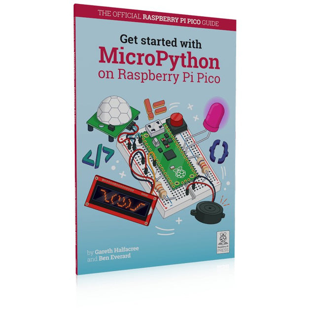
Raspberry Pi Foundation Get Started with MicroPython on Raspberry Pi Pico
In Get Started with MicroPython on Raspberry Pi Pico, you will learn how to use the beginner-friendly language MicroPython to write programs and connect up hardware to make your Raspberry Pi Pico interact with the world around it. Using these skills, you can create your own electro‑mechanical projects, whether for fun or to make your life easier. Microcontrollers, like RP2040 at the heart of Raspberry Pi Pico, are computers stripped back to their bare essentials. You don’t use monitors or keyboards, but program them to take their input from, and send their output to the input/output pins. Using these programmable connections, you can light lights, make noises, send text to screens, and much more. In Get Started with MicroPython on Raspberry Pi Pico, you will learn how to use the beginner-friendly language MicroPython to write programs and connect up hardware to make your Raspberry Pi Pico interact with the world around it. Using these skills, you can create your own electro‑mechanical projects, whether for fun or to make your life easier. The robotic future is here – you just have to build it yourself. We’ll show you how. About the authors Gareth Halfacree is a freelance technology journalist, writer, and former system administrator in the education sector. With a passion for open-source software and hardware, he was an early adopter of the Raspberry Pi platform and has written several publications on its capabilities and flexibility. Ben Everard is a geek who has stumbled into a career that lets him play with new hardware. As the editor of HackSpace magazine, he spends more time than he really should experimenting with the latest (and not-solatest) DIY tech.
€ 19,95€ 9,95
Members identical
-
Raspberry Pi Foundation Official Micro-USB Power Supply for Raspberry Pi
Official Micro-USB Power Supply for Raspberry Pi (12.5 W) Input: 100-240 VAC Output: 5.1 V / 2.5 A power supply Connector: micro USB Length: 1.5 m
€ 9,95€ 4,95
Members identical
-
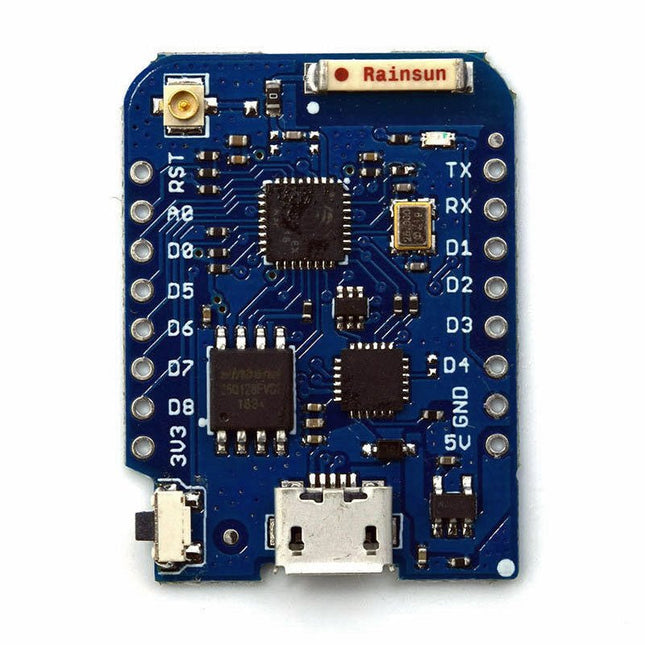
Wemos Wemos D1 mini Pro - ESP8266 based WiFi Module
This mini WiFi board has 16 MB flash, external antenna connector and built-in ceramic antenna based on ESP8266EX. Features 11 digital input/output pins Interrupt/pwm/I²C/one-wire 1 analog input (3.2 V max input) 16 MB Flash External antenna connector Built-in ceramic antenna CP2104 USB-TO-UART IC Specifications Operating Voltage 3.3 V Digital I/O Pins 11 Analog Input Pins 1 (3.2 V max) Clock Speed 80/160 MHz Flash 16 MB Size 34.2 x 25.6 mm Weight 3 g Pin Configuration Pin Function ESP8266 Pin RX RXD RXD A0 Analog input, max 3.2 V A0 D0 IO GPIO16 D1 IO, SCL GPIO5 D2 IO, SDA GPIO4 D3 IO, 10k Pull-up GPIO0 D4 IO, 10k Pull-up, BUILTIN_LED GPIO2 D5 IO, SCK GPIO14 D6 IO, MISO GPIO12 D7 IO, MOSI GPIO13 D8 IO, 10k Pull-down, SS GPIO15 G Ground GND 5V 5 V - 3V3 3.3 V 3.3 V RST Reset RST Included 1x Wemos D1 mini Pro (based on ESP8266EX) 2x Pin header (short) 2x Female connector strip (short) 2x Female connector strip (long)
€ 14,95€ 7,50
Members identical
-
Elektor Classics The Elektor Power Supply Collection (USB Stick)
More than 200 power supply designs for home construction This USB Stick contains over 200 different power supply circuits from the volumes 2001-2022 of Elektor. The article search feature allows you to search full-text content. The results are always displayed as pre-formatted PDF documents. Highlights Cuk Converter Automatic Battery Switchover Battery Voltage LED Digital Benchtop Power Supply Lithium-Ion Charger Solar Cell Charger Electronic Fuse High Voltage Regulator Power Supply for USB Devices Step-up Converter for LEDs Battery Management and much more... On the Stick you will also find a folder with additional material such as PCB layouts, Gerber files and software.
€ 49,95€ 24,95
Members identical
-
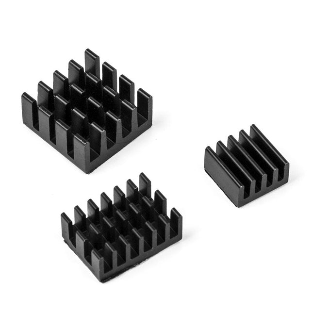
Kuongshun Heatsink Set for Raspberry Pi (black)
3-in-1 Aluminum Heatsink Set for Raspberry Pi 4 and 5 Contents 1x 14x14x6 mm 1x 15x10x5 mm 1x 8.8x8.8x5 mm
€ 3,95€ 1,95
Members identical
-
The RF & Communications Collection (USB Stick)
This USB stick holds a selection of more than 350 articles on RF, Radio and Communication published in Elektor Magazine. The content consists of both background articles and projects with the following topics: Basic radio-related circuits as well as more complex circuits like filters, oscillators, and amplifiers. Design, construction, and theory of antennas for transmitting and receiving radio signals efficiently. Design and analysis of RF circuits including filters, mixers, PLLs, and frequency synthesizers. Tools and techniques for predicting radio wave propagation paths and measuring RF signal strength. Techniques for processing digital signals in RF systems, including modulation and demodulation methods. Projects on radio receivers, AM, FM, SSB, CW, DRM, DAB, DAB+, Software Defined Radio, and more. Projects on Wi-Fi, Bluetooth, LoRaWAN, and more. You can use the article search function to locate specific content in the full text. The results are always shown as preformatted PDF documents. You can use Adobe Reader to browse articles, and you can use Adobe Reader’s integrated search functions to find instances of individual words and expressions.
€ 49,95€ 24,95
-
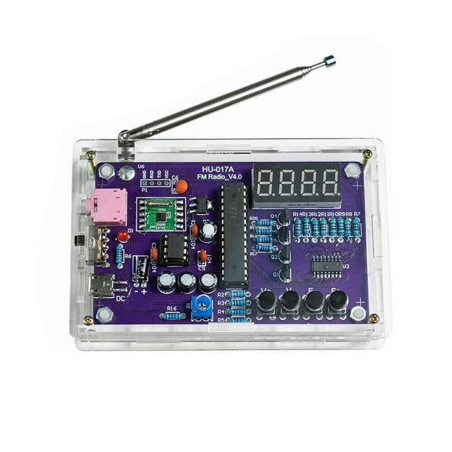
Generic FM Radio Kit
This DIY kit (HU-017A) is a wireless FM radio receiver with a 4-digit 7-segment display. It operates within the global FM receiving frequency band of 87.0-108.0 MHz, making it suitable for use in any country or region. The kit offers two power supply modes, allowing you to use it both at home and outdoors. This DIY electronic product will help you understand circuits and improve your soldering skills. Features 87.0-108.0 MHz FM Radio: Built-in RDA5807 FM data processor with a standard FM receiving frequency band. The FM frequency can be adjusted using the F+ and F- buttons. Adjustable Volume: Two volume adjustment methods – button and potentiometer. There are 15 volume levels. Active & Passive Audio Output: The kit has a built-in 0.5 W power amplifier to drive 8 Ω speakers directly. It also outputs audio signals to headsets or loudspeakers with AUX interfaces, allowing personal listening and sharing of FM audio. Configured with a 25 cm dedicated FM antenna and a (red) 4-digit 7-segment display for real-time display of FM radio frequency. The transparent acrylic shell protects the internal circuit board. It supports dual power supply methods – 5 V USB and 2x 1.5 V (AA) batteries. DIY Hand Soldering: The kit comes with various components that need to be installed manually. It helps exercise and improve soldering skills, making it suitable for electronics hobbyists, beginners, and educational purposes. Specifications Operating voltage DC 3 V/5 V Output impedance 8 Ω Output power 0.5 W Output channel Mono Receiver frequency 87.0 MHz~108.0 MHz Frequency accuracy 0.1 MHz Operating temperature −40°C to +85°C Operating humidity 5% to 95% RH Dimensions 107 x 70 x 23 mm IMPORTANT: Remove the batteries when powering the radio over to USB. Included 1x PCB 1x RDA5807M FM Receiver 1x STC15W404AS MCU 1x IC Socket 1x 74HC595D Register 1x TDA2822M Amplifier 1x IC Socket 1x AMS1117-3.3 V Voltage Converter 18x Metal Film Resistor 1x Potentiometer 4x Ceramic Capacitor 5x Electrolytic Capacitor 4x S8550 Transistor 1x Red LED 1x 4-digit 7-segment Display 1x Toggle Switch 1x SMD Micro USB Socket 1x Radio Antenna 1x AUX Audio Socket 4x Black Button 4x Button Cap 1x 0.5 W/8 Ω Speaker 1x Red/Black Wire 2x Double-sided adhesive 1x AA Battery Box 1x USB cable 6x Acrylic Board 4x Nylon Column Screw 4x M3 Screw 4x M3 Nut 4x M2x22 mm Screw 1x M2x6 mm Screw 5x M2 Nut
€ 29,95€ 14,95
Members identical
-

PiKVM PiKVM V3 KVM over IP for Raspberry Pi 4
PiKVM V3 is an open-source Raspberry Pi-based KVM over IP device. It will help you to manage servers or workstations remotely, whatever the state of the operating system or whether one is installed. PiKVM V3 allows you to turn on/off or restart your computer, configure the UEFI/BIOS, and even reinstall the OS using the virtual CD-ROM or flash drive. You can use your remote keyboard and mouse or PiKVM can simulate a keyboard, mouse, and a monitor, which are then presented in a web browser as if you were working on a remote system directly. Features HDMI Full HD capture based on the TC358743 chip (extra low latency ~100 ms and many features like compression control). OTG Keyboard & mouse; Mass Storage Drive emulation. Ability to simulate 'removal and insertion' for USB. Onboard ATX power control Onboard fan controller Real-time clock (RTC) RJ-45 and USB serial console port (to manage PiKVM OS or to connect with the server). Optional AVR-based HID (for some rare and strange motherboards whose BIOS doesn't understand the OTG emulated keyboard). Optional OLED screen to display network status or other desired information. Ready-made board. No need for soldering or breadboarding. PiKVM OS – the software is fully open. Included PiKVM V3 HAT board for Raspberry Pi 4 USB-C bridge board – to connect the HAT with Pi over USB-C ATX controller adapter board and wiring – to connect the HAT to the motherboard (if you want to manage power supply through hardware). 2 flat CSI cables Screws and brass standoffs Required Raspberry Pi 4 MicroSD card USB-C to USB-A cable HDMI cable Straight Ethernet cable (for the ATX expansion board connection) Power supply unit (5.1 V/3 A USB-C, officiel RPi power supply is recommended) Downloads User Guide Images GitHub Links The PiKVM Project and Lessons Learned: Q&A with PiKVM creator and developer Maxim Devaev PiKVM: Raspberry Pi as a KVM Remote Control
€ 229,00€ 114,50
Members identical
-
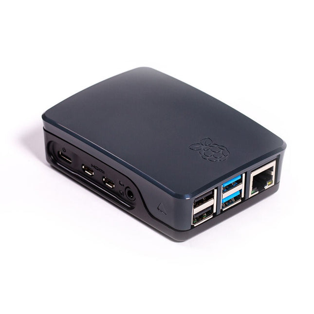
Raspberry Pi Foundation Official Case for Raspberry Pi 4 (black/gray)
Official Case for Raspberry Pi 4 (black/gray)
€ 7,95€ 3,95
Members identical
-
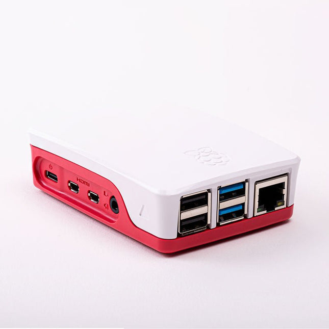
Raspberry Pi Foundation Official Case for Raspberry Pi 4 (white/red)
Official Case for Raspberry Pi 4 (white/red)
€ 7,95€ 3,95
Members identical
-

Raspberry Pi Foundation Official Raspberry Pi Mini-HDMI to HDMI Adapter Cable
This short cable (10 cm) connects a standard HDMI cable to the Mini-HDMI port of a Raspberry Pi Zero.
€ 3,95€ 1,95
Members identical
-
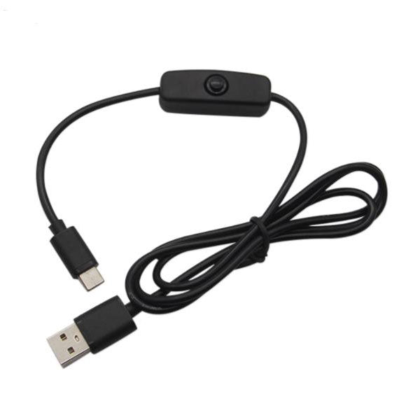
Kuongshun USB-A to USB-C Cable with ON/OFF Switch
Features Type C cable USB type C is suitable for new version Raspberry Pi 4 No need to pull the cable to restart or reboot your Pi, just press the button to turn your Pi on and off Can be used as power supply for the Pi up to 2 Amp Help prevent the Pi's USB connector from wear and tear due to frequently pulling and inserting the USB cable Specifications Interface: USB Type C Current: 3 A Length: 1.5 m Use for: Raspberry Pi 4 Model B Packing List: 1x USB Type C power cable
€ 4,95€ 2,50
Members identical


