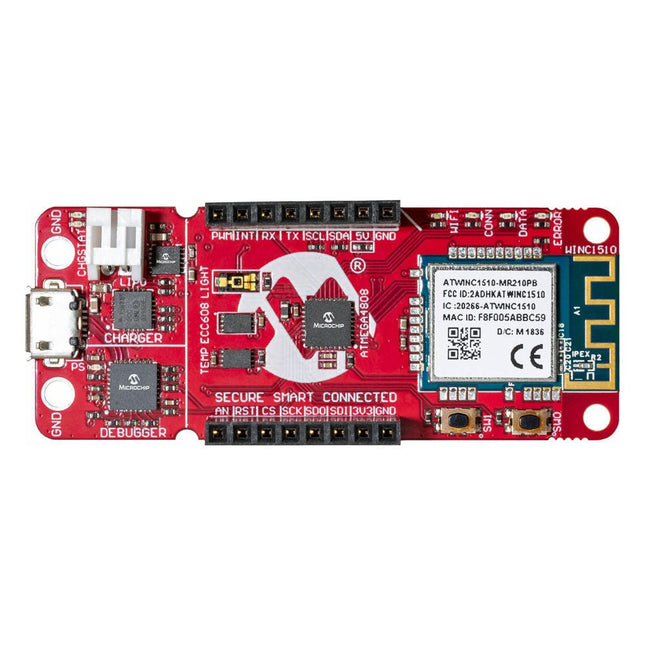
The AVR-IoT WA development board combines a powerful ATmega4808 AVR MCU, an ATECC608A CryptoAuthentication secure element IC and the fully certified ATWINC1510 Wi-Fi network controller – which provides the most simple and effective way to connect your embedded application to Amazon Web Services (AWS). The board also includes an on-board debugger, and requires no external hardware to program and debug the MCU.
Out of the box, the MCU comes preloaded with a firmware image that enables you to quickly connect and send data to the AWS platform using the on-board temperature and light sensors. Once you are ready to build your own custom design, you can easily generate code using the free software libraries in Atmel START or MPLAB Code Configurator (MCC).
The AVR-IoT WA board is supported by two award-winning Integrated Development Environments (IDEs) – Atmel Studio and Microchip MPLAB X IDE – giving you the freedom to innovate with your environment of choice.
Features
ATmega4808 microcontroller
Four user LED’s
Two mechanical buttons
mikroBUS header footprint
TEMT6000 Light sensor
MCP9808 Temperature sensor
ATECC608A CryptoAuthentication™ device
WINC1510 WiFi Module
On-board Debugger
Auto-ID for board identification in Atmel Studio and Microchip MPLAB X
One green board power and status LED
Programming and debugging
Virtual COM port (CDC)
Two DGI GPIO lines
USB and battery powered
Integrated Li-Ion/LiPo battery charger
The SparkFun RedBoard Qwiic is an Arduino-compatible board that combines features of different Arduinos with the Qwiic Connect System.
Features
ATmega328 microcontroller with Optiboot Bootloader
R3 Shield Compatible
CH340C Serial-USB Converter
3.3 V to 5 V Voltage Level Jumper
A4 / A5 Jumpers
AP2112 Voltage Regulator
ISP Header
Input voltage: 7 V - 15 V
1 Qwiic Connector
16 MHz Clock Speed
32 k Flash Memory
All SMD Construction
Improved Reset Button
Features
Compatible with Raspberry Pi 4 only
Cutout in lid for 40x30mm heatsink or Fan SHIM
Super-slimline profile
Fully HAT-compatible
Protects your beloved Pi
Clear top and base leave Raspberry Pi 4 visible
GPIO cut-out
Handy laser-etched port labels
Leaves all ports accessible
Made from lightweight, high-quality, cast acrylic
Great for hacking and tinkering!
Made in Sheffield, UK
Weighing just over 50 grams, the case is lightweight and ideal for mounting to any surface. No tools are required for assembly or disassembly. The dimensions are: 99 × 66 × 15 mm.
In the video below you can see a quick assembly guide.
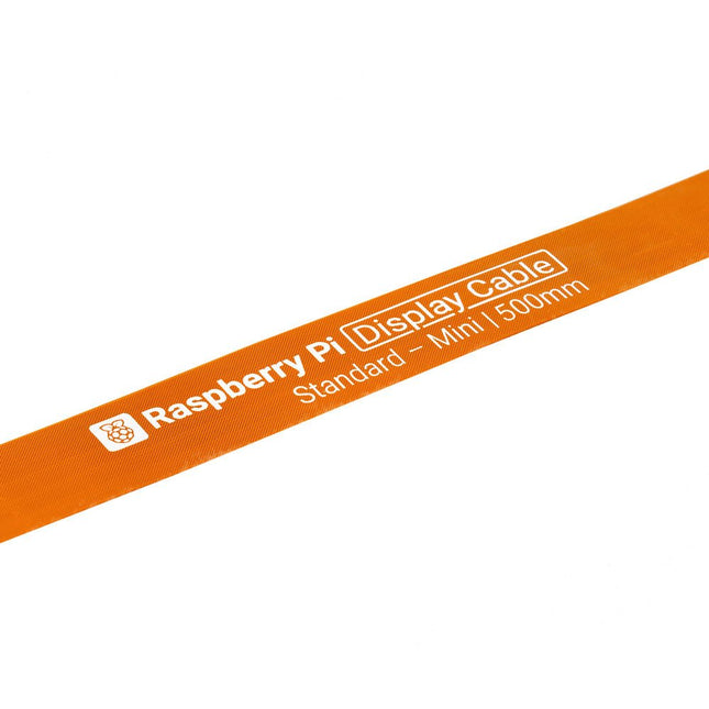
Raspberry Pi 5 provides two four-lane MIPI connectors, each of which can support either a camera or a display. These connectors use the same 22-way, 0.5 mm-pitch “mini” FPC format as the Compute Module Development Kit, and require adapter cables to connect to the 15-way, 1 mm-pitch “standard” format connectors on current Raspbery Pi camera and display products.These mini-to-standard adapter cables for cameras and displays (note that a camera cable should not be used with a display, and vice versa) are available in 200 mm, 300 mm and 500 mm lengths.
The Raspberry Pi A+ Case has been designed to fit both the Pi 3 Model A+ and the Pi 1 Model A+. The high-quality ABS construction consists of two parts. The base features cut-outs to allow access to the microSD Card and the the HDMI, audio/video and USB ports, as well as the power connector.
Plug a reader into the headers, use a Qwiic cable, scan your 125kHz ID tag, and the unique 32-bit ID will be shown on the screen. The unit comes with a read LED and buzzer, but don't worry, there is a jumper you can cut to disable the buzzer if you want. Utilizing SparkFun's handy Qwiic system, no soldering is required to connect it to the rest of your system. However, we still have broken out 0.1"-spaced pins if you prefer to use a breadboard.
Utilizing the onboard ATtiny84A, the Qwiic RFID takes the six byte ID tag of your 125kHz RFID card, attaches a timestamp to it, and puts it onto a stack that holds up to 20 unique RFID scans at a time. This information is easy to get at with some simple I²C commands.
Raspberry Pi 5 provides two four-lane MIPI connectors, each of which can support either a camera or a display. These connectors use the same 22-way, 0.5 mm-pitch “mini” FPC format as the Compute Module Development Kit, and require adapter cables to connect to the 15-way, 1 mm-pitch “standard” format connectors on current Raspbery Pi camera and display products.These mini-to-standard adapter cables for cameras and displays (note that a camera cable should not be used with a display, and vice versa) are available in 200 mm, 300 mm and 500 mm lengths.
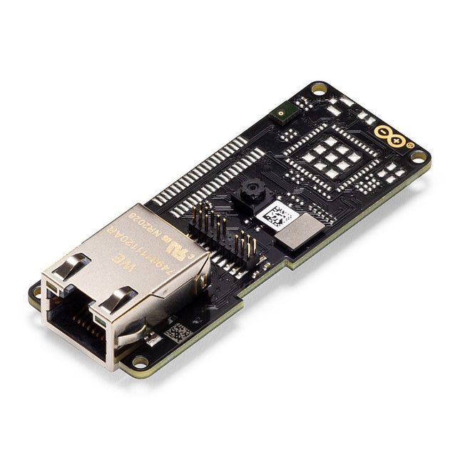
The Arduino Pro Portenta Vision Shield brings industry-rated features to your Portenta. This hardware add-on will let you run embedded computer vision applications, connect wirelessly or via Ethernet to the Arduino Cloud or your own infrastructure, and activate your system upon the detection of sound events.
Features
324x324 pixels camera sensor: use one of the cores in Portenta to run image recognition algorithms using the OpenMV for Arduino editor
100 Mbps Ethernet connector: get your Portenta H7 connected to the wired Internet
2 onboard microphones for directional sound detection: capture and analyse sound in real-time
JTAG connector: perform low-level debugging of your Portenta board or special firmware updates using an external programmer
SD-Card connector: store your captured data in the card, or read configuration files
The Vision Shield has been designed to fit on top of the Arduino Portenta family. The Portenta boards feature multicore 32-bit ARM Cortex processors running at hundreds of megahertz, with megabytes of program memory and RAM. Portenta boards come with WiFi and Bluetooth.
Embedded Computer Vision Made Easy
Arduino has teamed up with OpenMV to offer you a free license to the OpenMV IDE, an easy way into computer vision using MicroPython as a programming paradigm. Download the OpenMV for Arduino Editor from our professional tutorials site and browse through the examples we have prepared for you inside the OpenMV IDE. Companies across the whole world are already building their commercial products based on this simple-yet-powerful approach to detect, filter, and classify images, QR codes, and others.
Debugging With Professional Tools
Connect your Portenta H7 to a professional debugger through the JTAG connector. Use professional software tools like the ones from Lauterbach or Segger on top of your board to debug your code step by step. The Vision Shield exposes the required pins for you to plug in your external JTAG.
Camera
Himax HM-01B0 camera module
Resolution
320 x 320 active pixel resolution with support for QVGA
Image sensor
High sensitivity 3.6μ BrightSense pixel technology
Microphone
2 x MP34DT05
Length
66 mm
Width
25 mm
Weight
11 gr
For more information, check out the tutorials provided by Arduino here.
The Challenger RP2040 NFC is a small embedded computer, equipped with an advanced on-board NFC controller (NXP PN7150), in the popular Adafruit Feather form factor. It is based on an RP2040 microcontroller chip from the Raspberry Pi Foundation which is a dual-core Cortex-M0 that can run on a clock up to 133 MHz.
NFC
The PN7150 is a full featured NFC controller solution with integrated firmware and NCI interface designed for contactless communication at 13.56 MHz. It is fully compatible with NFC forum requirements and is greatly designed based on learnings from previous NXP NFC device generation. It is the ideal solution for rapidly integrating NFC technology in any application, especially small embedded systems reducing Bill of Material (BOM).
The integrated design with full NFC forum compliancy gives the user all the following features:
Embedded NFC firmware providing all NFC protocols as pre-integrated feature.
Direct connection to the main host or microcontroller, by I²C-bus physical and NCI protocol.
Ultra-low power consumption in polling loop mode.
Highly efficient integrated power management unit (PMU) allowing direct supply from a battery.
Specifications
Microcontroller
RP2040 from Raspberry Pi (133 MHz dual-core Cortex-M0)
SPI
One SPI channels configured
I²C
Two I²C channel configured (dedicated I²C for the PN7150)
UART
One UART channel configured
Analog inputs
4 analog input channels
NFC module
PN7150 from NXP
Flash memory
8 MB, 133 MHz
SRAM memory
264 KB (divided into 6 banks)
USB 2.0 controller
Up to 12 MBit/s full speed (integrated USB 1.1 PHY)
JST Battery connector
2.0 mm pitch
On board LiPo charger
450 mA standard charge current
Dimensions
51 x 23 x 3,2 mm
Weight
9 g
Note: Antenna is not included.
Downloads
Datasheet
Quick start example
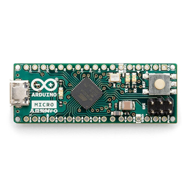
The Arduino Micro contains everything needed to support the microcontroller; simply connect it to a computer with a micro USB cable to get started. It has a form factor that enables it to be easily placed on a breadboard.
The Micro board is similar to the Arduino Leonardo in that the ATmega32U4 has built-in USB communication, eliminating the need for a secondary processor. This allows the Micro to appear to a connected computer as a mouse and keyboard, in addition to a virtual (CDC) serial / COM port.
Specifications
Microcontroller
ATmega32U4
Operating Voltage
5 V
Input Voltage
7 V - 12 V
Analog Input Pins
12
PWM Pins
7
DC I/O Pin
20
DC Current per I/O Pin
20 mA
DC Current for 3.3 V Pin
50 mA
Flash Memory
32 KB of which 4 KB used by the bootloader
SRAM
2.5 KB
EEPROM
1 KB
Clock Speed
16 MHz
LED_Builtin
13
Length
45 mm
Width
18 mm
Weight
13 g
Pico Breakout Garden Base sits underneath your Pico and lets you connect up to six of our extensive selection of Pimoroni breakouts to it. Whether it's environmental sensors so you can keep track of the temperature and humidity in your office, a whole host of little screens for important notifications and readouts, and, of course, LEDs. Scroll down for a list of breakouts that are currently compatible with our C++/MicroPython libraries!As well as a labelled landing area for your Pico, there's also a full set of broken out Pico connections, in case you need to attach even more sensors, wires, and circuitry. We've thrown in some rubber feet to keep the base nice and stable and to stop it from scratching your desk, or there are M2.5 mounting holes at the corners so that you can bolt it onto a solid surface if you prefer.The six sturdy black slots are edge connectors that connect the breakouts to the pins on your Pico. There's two slots for SPI breakouts, and four slots for I²C breakouts. Because I²C is a bus, you can use multiple I²C devices at the same time, providing they don't have the same I²C address (we've made sure that all of our breakouts have different addresses, and we print them on the back of the breakouts so they're easy to find).As well as being a handy way to add functionality to your Pico, Breakout Garden is also very useful for prototyping projects without the need for complicated wiring, soldering, or breadboards, and you can grow or change up your setup at any time.Features
Six sturdy edge-connector slots for breakouts
4x I²C slots (5 pins)
2x SPI slot (7 pins)
Landing area with female headers for Raspberry Pi Pico
0.1” pitch, 5 or 7 pin connectors
Broken-out pins
Reverse polarity protection (built into breakouts)
99% assembled – just need to stick on the feet!
Compatible with Raspberry Pi Pico
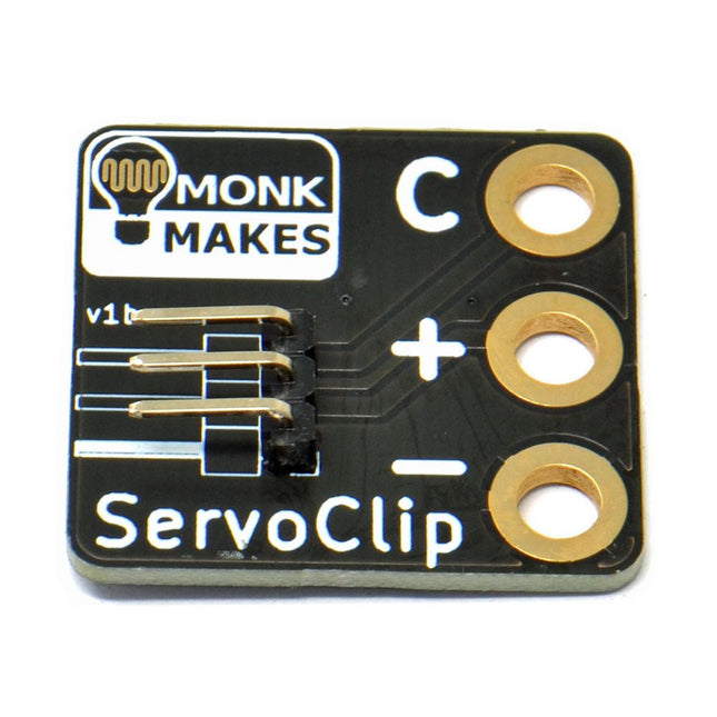
An adapter for connecting a servo meter with croc/alligator clips.
This is a handy little clip to connect a servo motor with 5.4 mm header socket using alligator clips. It is ideal for use with boards like the BBC micro:bit and Adafruit's Circuit Playground Express or Gemma.
Width: 27 mm
Height: 35 mm
Downloads
Datasheet
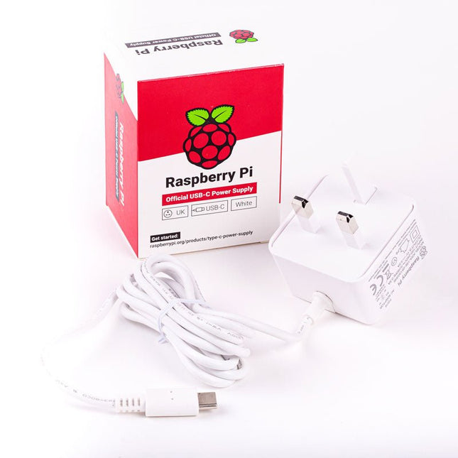
The Raspberry Pi USB-C power supply is designed specifically to power the latest Raspberry Pi 4 Model B computers.
The power supply features a USB-C cable and is available in four different models to suit different international power sockets, and in two colors.
Specifications
Output
Output voltage
+5.1 V DC
Minimum load current
0 A
Nominal load current
3.0 A
Maximum power
15.3 W
Load regulation
±5 %
Line regulation
±2 %
Ripple & noise
120 mVp-p
Rise time
100 ms maximum to regulation limits for DC outputs
Turn-on delay
3000 ms maximum at nominal input AC voltage and full load
Protection
Short circuit protectionOvercurrent protectionOver temperature protection
Efficiency
81% minimum (output current from 100%, 75%, 50%, 25%)72% minimum at 10% load
Output cable
1.5 m 18AWG
Output connector
USB Type-C
Input
Voltage range
100-240 VAC (rated)96-264 VAC (operating)
Frequency
50/60 Hz ±3 Hz
Current
0.5 A maximum
Power consumption (no load)
0.075 W maximum
Inrush current
No damage shall occur, and the input fuse shall not blow
Operating ambient temperature
0-40°C
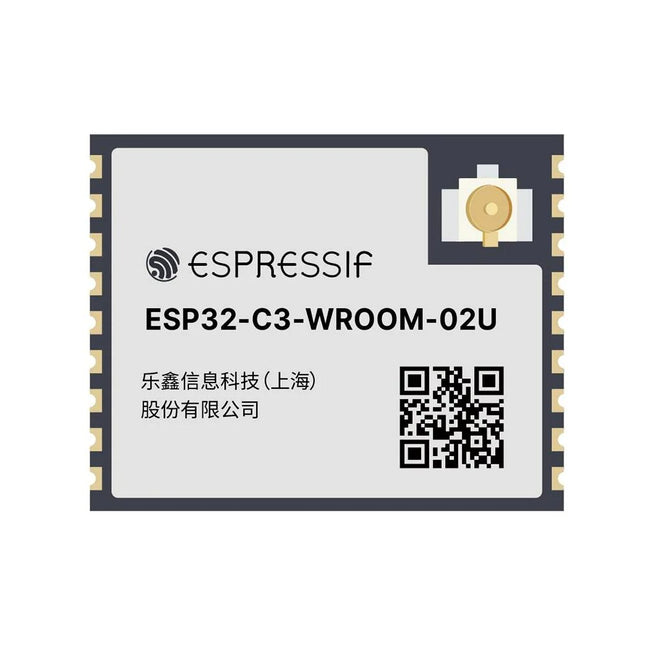
ESP32-C3-WROOM-02U is a general-purpose Wi-Fi and Bluetooth LE module. The rich set of peripherals and high performance make the module an ideal choice for smart homes, industrial automation, health care, consumer electronics, etc.
ESP32-C3-WROOM-02U features an external SPI flash and comes with a connector for an external antenna.
ESP32-C3-WROOM-02U has an operating ambient temperature option of –40∼85°C, embedded with the ESP32-C3 chip. ESP32-C3 has a 32-bit RISC-V single-core processor. It integrates a rich set of peripherals, ranging from UART, I²C, I²S, remote control peripheral, LED PWM controller, general DMA controller, TWAI controller, USB Serial/JTAG controller, temperature sensor, ADC, etc. It also includes SPI, Dual SPI and Quad SPI interfaces.
Features
Flash: 4 MB (Quad SPI)
Dimensions: 18.0 x 20.0 x 3.2 mm
Downloads
Datasheet
Waveshare DVK600 is an FPGA CPLD mother board that features expansion connectors for connecting FPGA CPLD core board and accessory boards. DVK600 provides an easy way to set up FPGA CPLD development system.
Features
FPGA CPLD core board connector: for easily connecting core boards which integrate an FPGA CPLD chip onboard
8I/Os_1 interface, for connecting accessory boards/modules
8I/Os_2 interface, for connecting accessory boards/modules
16I/Os_1 interface, for connecting accessory boards/modules
16I/Os_2 interface, for connecting accessory boards/modules
32I/Os_1 interface, for connecting accessory boards/modules
32I/Os_2 interface, for connecting accessory boards/modules
32I/Os_3 interface, for connecting accessory boards/modules
SDRAM interface
for connecting SDRAM accessory board
also works as FPGA CPLD pins expansion connectors
LCD interface, for connecting LCD22, LCD12864, LCD1602
ONE-WIRE interface: easily connects to ONE-WIRE devices (TO-92 package), such as temperature sensor (DS18B20), electronic registration number (DS2401), etc.
5 V DC jack
Joystick: five positions
Buzzer
Potentiometer: for LCD22 backlight adjustment, or LCD12864, LCD1602 contrast adjustment
Power switch
Buzzer jumper
ONE-WIRE jumper
Joystick jumper
Downloads
Schematics
Thanks to its six sturdy slots, Breakout Garden enables the users to simply plug and play with various tiny breakout board.
Just insert one or more boards into the slots in the Breakout Garden HAT and you’re ready to go. The mini breakouts feel secure enough in the edge-connector slots and are very unlikely to fall out.
There are a number of useful pins along the top of Breakout Garden, which lets you connect other devices and integrate them into your project.
You shouldn't be worried if you insert a board the wrong way thanks to provided reverse polarity protection. It doesn't matter which slot you use for each breakout either, because the I²C address of the breakout will be recognised by the software and it'll detect them correctly in case you move them around.
Features
Six sturdy edge-connector slots for Pimoroni breakouts
0.1” pitch, 5 pin connectors
Broken-out pins (1 × 10 strip of male header included)
Standoffs (M2.5, 10 mm height) included to hold your Breakout Garden securely
Reverse polarity protection (built into breakouts)
HAT format board
Compatible with Raspberry Pi 3 B+, 3, 2, B+, A+, Zero, and Zero W
It's suggested using the included standoffs to attache Breakout Garden to your Raspberry Pi.
Software
Breakout Garden doesn't require any software of its own, but each breakout you use will need a Python library. On the Breakout Garden GitHub page you'll find an automatic installer, which will install the appropriate software for a given breakout. There are also some examples that show you what else you can do with Breakout Garden.
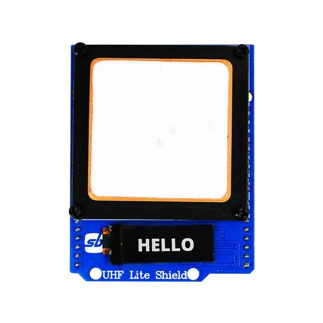
Designed with cutting-edge technology, this shield brings the power of Ultra High Frequency (UHF) RFID to your fingertips.
With the Ardi UHF Shield, you can effortlessly read up to an impressive 50 tags per second, allowing for fast and efficient data collection. The shield features an onboard UHF antenna, ensuring reliable and accurate tag detection even in challenging environments.
Equipped with a high-performance 0.91" OLED display, the Ardi UHF Shield provides clear and concise visual feedback, making it easy to monitor and interact with the RFID readings. Whether you're tracking inventory, managing access control, or implementing a smart attendance system, this shield has you covered.
With a remarkable 1-meter reading distance, the Ardi UHF Shield offers an extended range for capturing RFID data. Say goodbye to the limitations of proximity-based RFID systems and embrace the flexibility and convenience of a wider reading range.
The shield provides read-write capabilities, allowing you to not only retrieve information from RFID tags but also update or modify data as needed. This versatility opens up a world of possibilities for advanced applications and custom solutions.
Features
Onboard High-performance UHF RFID reader module
24 hours x 365 days’ work normally
0.91” OLED display for visual interaction with shield
Multi-tone Buzzer onboard for Audio alerts
Shield compatible with both 3.3 V and 5 V MCU
Mounts directly onto ArdiPi, Ardi32 or other Arduino compatible boards
Specifications
OLED resolution 128x32 pixels
I²C Interface for OLED
UHF Frequency Range (EU/UK): 865.1-867.9 MHz
UHF Module Type: Read/Write
Protocols Supported: EPCglobal UHF Class 1 Gen 2 / ISO 18000-6C
Reading Distance: 1 meters
Can identify over 50 tags simultaneously
Communication interface: TTL UART Interface for UHF
Communication baud rate: 115200 bps (default and recommend) – 38400 bps
Operation current: 180 mA @ 3.5 V (26 dBm Output, 25°C), 110 mA @ 3.5 V (18 dBm Output, 25°C)
Working humidity <95% (+25°C)
Heat-dissipating method Air cooling(no need out install cooling fin)
Tags storage capacity: 200 pcs tags @ 96 bit EPC
Output power: 18-26 dBm
Output power accuracy: +/-1 dB
Tags RSSI support
This is a high-performance cooling solution designed to effectively dissipate heat and ensure optimal operating temperatures for the Raspberry Pi. It is an essential accessory for users who want to enhance the performance and longevity of their Raspberry Pi device.
The compact design of the Water cooling kit for Raspberry Pi 5 allows it to be seamlessly installed on the top and bottom of the Raspberry Pi 5, ensuring efficient heat transfer and perfectly protecting the bottom of the Raspberry Pi. Its simple installation process eliminates the need for complex wiring or additional tools, making it friendly to both beginners and experienced Raspberry Pi enthusiasts.
With its powerful cooling performance, the water cooling kit for Raspberry Pi 5 for effectively dissipates heat generated by the Raspberry Pi during intensive tasks or prolonged usage. This helps prevent overheating and ensures stable performance. Efficient water-cooled cooling will allow you to connect multiple Raspberry Pi boards to a set of cooling devices. When using Raspberry Pi in a cluster, you can use a set of water-cooled devices to effectively cool multiple Raspberry Pi boards.
Features
Made for Raspberry Pi: Specially designed for Raspberry Pi 5, 1:1 mold opening, covering all heat sources, including CPU, Wi-Fi, power chip, and eMMC.
Cooling Performance: Effectively dissipates the heat generated by the Raspberry Pi, ensuring optimal operating temperatures and preventing overheating.
Easy to Use: The integrated design of the water pump and cooling fan is convenient for users to install.
RGB Color Lighting: RGB-colored lights are installed at the fan and water pump locations.
Included
1x Water cooling kit
1x Water cooling radiator
1x Black heatsink
2x Silicone hose
1x 12 V/2 A power adapter (US)
4x Hexagonal screw M2.5x10
1x L-key hex wrench
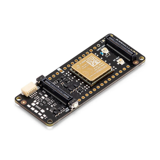
The Arduino Pro Portenta Cat. M1/NB IoT GNSS Shield allows you to enhance the connectivity features of your Portenta H7 applications. The shield leverages a Cinterion TX62 wireless module by Thales, designed for highly efficient, low-power IoT applications to deliver optimized bandwidth and performance.
The Portenta Cat. M1/NB IoT GNSS Shield combines with the strong edge computing power of the Portenta H7 to enable the development of asset tracking and remote monitoring applications in industrial settings, as well as in agriculture, public utilities and smart cities. The shield offers cellular connectivity to both Cat. M1 and NB-IoT networks with the option to use eSIM technology. Easily track your valuables – across the city or worldwide – with your choice of GPS, GLONASS, Galileo or BeiDou.
Features
Change connectivity capabilities without changing the board
Add NB-IoT, CAT. M1 and positioning to any Portenta product
Possibility to create a small multiprotocol router (WiFi - BT + NB-IoT/CAT. M1)
Greatly reduce communication bandwidth requirements in IoT applications
Low-power module
Compatible also with MKR boards
Remote Monitoring
Industrial and agricultural companies can leverage the Portenta Cat. M1/NB IoT GNSS Shield to remotely monitor gas detectors, optical sensors, machinery alarm systems, biological bug traps and more.
Technology providers providing smart city solutions can compound the power and reliability of the Portenta H7 with the Portenta Cat. M1/NB IoT GNSS Shield, to connect data and automate actions for a truly optimized use of resources and enhanced user experience.
Asset Monitoring
Add monitoring capabilities to any asset by combining the performance and edge computing features of the Portenta family boards. The Portenta Cat. M1/NB IoT GNSS Shield is ideal to monitor valuable goods and also for monitoring industrial machinery and equipment.
Specifications
Connectivity
Cinterion TX62 wireless module; NB-IoT - LTE CAT.M1; 3GPP Rel.14 Compliant Protocol LTE Cat. M1/NB1/NB2; UMTS BANDS: 1 / 2 / 3 / 4 / 5 / 8 / 12(17) / 13 / 18 / 19 / 20 / 25 / 26 / 27 / 28 / 66 / 71 / 85; LTE Cat.M1 DL: max. 300 kbps, UL: max. 1.1 Mbps; LTE Cat.NB1 DL: max. 27 kbps, UL: max. 63 kbps; LTE Cat.NB2 DL: max. 124 kbps, UL: max. 158 kbps
Short messaging service (SMS)
Point-to-point mobile terminated (MT) and mobile originated (MO) Text Mode; Protocol Data Unit (PDU) Mode
Localization support
GNSS capability (GPS/BeiDou/Galileo/GLONASS)
Other
Embedded IPv4 and IPv6 TCP/IP stack access; Internet Services: TCP server/client, UDP client, DNS, Ping, HTTP client, FTP client, MQTT client Secure Connection with TLS/DTLS Secure boot
Dimensions
66 x 25.4 mm
Operating temperature
-40° C to +85° C (-104° F to 185°F)
Downloads
Datasheet
Schematics