Mastering Surface Mount Technology takes you on a crash course in techniques, tips and know-how to successfully introduce surface mount technology in your workflow. Even if you are on a budget you too can jumpstart your designs with advanced fine pitch parts.
Besides explaining methodology and equipment, attention is given to SMT parts technologies and soldering methods. In a step by step way, several projects introduce you to handling surface mount parts and the required skills to successfully build SMT assemblies. Many practical tips and tricks are disclosed that bring surface mount technology into everyone's reach without breaking the bank.
From SRPP and Mu-Follower to OTL Designs
Tube amplifiers suffer from distortion. Fortunately, circuits such as the SRPP amplifier, mu-follower, and beta-follower produce minimal distortion even at output voltages of 50 to 100 Vpeak.
These designs are often published with errors. Without a sound understanding of the theory, it is easy to arrive at a flawed design.
In the first section of this book, we investigate the origin of distortion, while in the second we investigate the design of and SRPP and a mu-follower.
On the internet we can find the most exotic designs. Evaluating them teaches us that these designs often make matters worse rather than better. In the chapter on incorrect SRPPs and mu-followers, we sometimes see bizarre and misguided designs where using a simple single-triode amplifier would perform much better.
Push-pull output stages also exist. A great number of them are examined, and their similarity to the SRPP is discussed. This is done especially with the help of the theory behind the OTL based on the ‘mother’ of all OTLs, the Philips HF303.
Finally, attention is given to frequency characteristics and technical matters such as the supply voltage and the filament power supply.
To illustrate these points, there are a few designs covering the subjects discussed.
This book presents much new theory that has not been published before. It is often an eye-opener, showing that many things have a beautiful and unexpected simplicity.
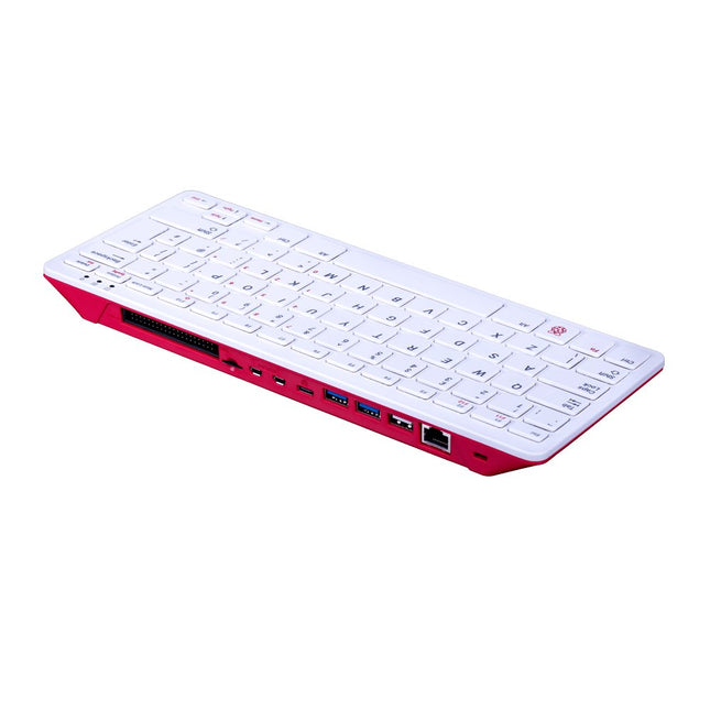
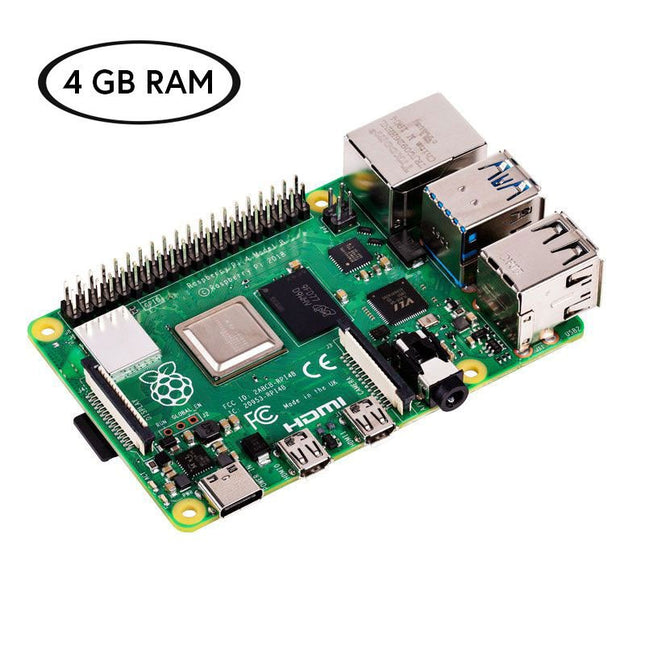
The Raspberry Pi 400 offers a quad-core 64-bit processor, 4 GB RAM, wireless networking, dual-display output, 4K video playback, and a 40-pin GPIO header. It's a powerful, compact computer built into a portable keyboard.
Specifications
Processor
Broadcom BCM2711 quad-core Cortex-A72 (ARM v8) 64-bit SoC @ 1.8 GHz
RAM
4 GB LPDDR4-3200
Connectivity
Dual-band (2.4 GHz and 5.0 GHz) IEEE 802.11b/g/n/ac wireless LANBluetooth 5.0, BLEGigabit Ethernet2x USB 3.0 and 1x USB 2.0 ports
GPIO
Horizontal 40-pin GPIO header
Video & Sound
2 × micro HDMI ports (supports up to 4Kp60)
Multimedia
H.265 (4Kp60 decode)H.264 (1080p60 decode, 1080p30 encode)OpenGL ES 3.0 graphics
SD card support
MicroSD card slot for operating system and data storage
Keyboard
US keyboard
Power
5 V DC via USB connector
Operating temperature
0°C to +40°C
Dimensions
286 x 122 x 23 mm (maximum)
Learn to program displays and GUIs with Python
This book is about Raspberry Pi 4 display projects. The book starts by explaining how to install the latest Raspbian operating system on an SD card, and how to configure and use the GPIO ports.
The core of the book explains the following topics in simple terms with fully tested and working example projects:
Simple LED projects
Bar graph LED projects
Matrix LED projects
Bitmap LED projects
LED strips
LCDs
OLED displays
E-paper displays
TFT displays
7-inch touch screen
GUI Programming with Tkinder
One unique feature of this book is that it covers almost all types of display that readers will need to use in their Raspberry Pi based projects. The operation of each project is fully given, including block diagrams, circuit diagrams, and commented full program listings. It is therefore an easy task to convert the given projects to run on other popular platforms, such as Arduino or PIC microcontrollers.
Python program listings of all Raspberry Pi projects developed in this book are available for download at Elektor.com. Readers can use these programs in their projects. Alternatively, they can modify the programs to suit their applications.
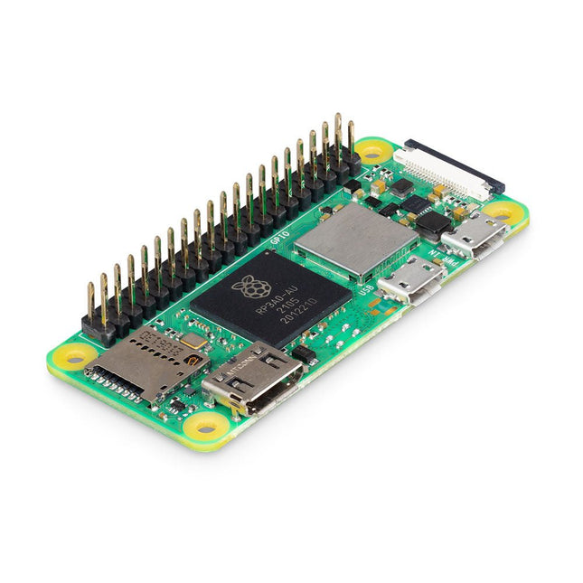
Raspberry Pi Zero 2 WH is the successor to the breakthrough Raspberry Pi Zero W(H). The board incorporates a quad-core 64-bit Arm Cortex-A53 CPU, clocked at 1 GHz. At its heart is a Raspberry Pi RP3A0 system-in-package (SiP), integrating a Broadcom BCM2710A1 die with 512 MB of LPDDR2 SDRAM. The upgraded processor provides Raspberry Pi Zero 2 WH with 40% more single-threaded performance, and five times more multi-threaded performance, than the original single-core Raspberry Pi Zero.
Features
64-bit quad-core processor
VideoCore IV GPU
512 MB LPDDR2 DRAM
802.11b/g/n wireless LAN
Bluetooth 4.2 / Bluetooth Low Energy (BLE)
MicroSD card slot
Mini HDMI and USB 2.0 OTG ports
Micro USB power
With mounted 40-pin header
Composite video and reset pins via solder test points
CSI camera connector
Specifications
SoC
Broadcom BCM2710A1
CPU
64-bit ARM Cortex-A53 (4x 1 GHz)
GPU
Broadcom VideoCore VI
RAM
512 MB LPDDR2
Wireless LAN
2.4 GHz IEEE 802.11b/g/n
Bluetooth
Bluetooth 4.2, BLE
USB
1x micro USB (for data)1x micro USB (for power supply)
GPIO
HAT-compatible 40-pin GPIO header
Video & Audio
1080P HD video & stereo audio via mini-HDMI connector
SD card
microSD (for operating system and storage)
Power
5 VDC / 2.5 A (supplied via micro USB connector)
Dimensions
65 x 30 x 5 mm
Raspberry Pi Zero 2 WH is footprint-compatible with earlier Zero models.
Most people are increasingly confronted with the applications of Artificial Intelligence (AI). Music or video ratings, navigation systems, shopping advice, etc. are based on methods that can be attributed to this field.
The term Artificial Intelligence was coined in 1956 at an international conference known as the Dartmouth Summer Research Project. One basic approach was to model the functioning of the human brain and to construct advanced computer systems based on this. Soon it should be clear how the human mind works. Transferring it to a machine was considered only a small step. This notion proved to be a bit too optimistic. Nevertheless, the progress of modern AI, or rather its subspecialty called Machine Learning (ML), can no longer be denied.
In this book, several different systems will be used to get to know the methods of machine learning in more detail. In addition to the PC, both the Raspberry Pi and the Maixduino will demonstrate their capabilities in the individual projects. In addition to applications such as object and facial recognition, practical systems such as bottle detectors, person counters, or a “talking eye” will also be created.
The latter is capable of acoustically describing objects or faces that are detected automatically. For example, if a vehicle is in the field of view of the connected camera, the information 'I see a car!' is output via electronically generated speech. Such devices are highly interesting examples of how, for example, blind or severely visually impaired people can also benefit from AI systems.
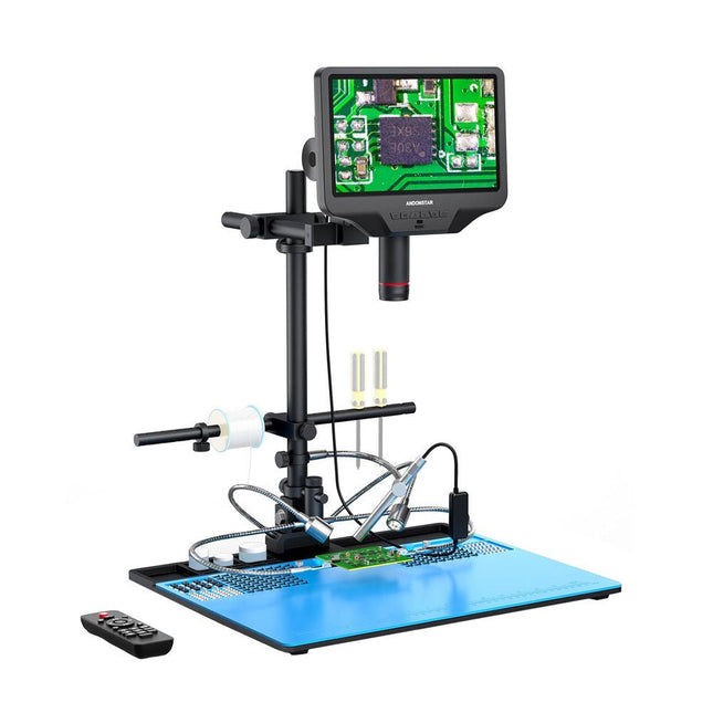
The Andonstar AD409 Max-ES boosts a high-quality metal lens and a unique UV filter design. Crafted from top-tier industrial-grade materials, it delivers unmatched precision and durability, ensuring a reliable product experience. The UV filter positioned in front of the metal lens blocks soldering heat, smoke, and dust, safeguarding the lens and making it perfect for soldering and maintenance professionals.
The AD409 Max-ES features an oversized Max station (46 x 37 x 47.5 cm) and an advanced tool set, expanding the soldering station area by 370%. This upgrade meets the demands of professional soldering tasks and provides ample workspace for larger projects.
The easy-to-use tool holder keeps tools within reach, ensuring they are always accessible. Additionally, the soldering helping hands with rotatable clamps simplify soldering and repair tasks, enhancing efficiency and convenience.
The endoscope offers an all-around 360° view. This allows for clear observation of components from all sides and inside pipes, eliminating blind spots and ensuring thorough inspections.
Features
High-quality Metal Lens and Unique UV Filter Design
New Max station
Easy-to-use Tool Holder and Soldering Helping Hands
Microscope with Endoscope All-around View 360°
Professional HDMI Digital Microscope supports Multiple Output Methods
8 Levels adjustable LEDs
Convenient Wireless Remote Control
Specifications
Screen size
10.1 inch (1280x800)
Image sensor
4 MP
Video output
UHD 2880x2160 (24fps)FHD 1920x1080 (60fps/30fps)HD 1280x720 (120fps)
Video format
MP4
Magnification
Up to 300 times (27 inch HDMI monitor)
Photo resolution
Max. 24 MP (5600x4200)
Photo format
JPG
Focus range
Min. 5 cm
Frame Rate
Max. 120fps
Video interface
HDMI
Storage
microSD card (up to 64 GB)
PC support
Windows, PC software with measurement
Mobile phone, tablet terminal support
Support WiFi connection and measurement
Power source
5 V DC
Light source
2 LEDs with the stand
Endoscope
Yes
Stand size
46 x 37 x 47.5 cm (18.1 x 14.6 x 18.7")
Included
1x Andonstar AD409 Max-ES Digital Microscope
1x Endoscope
1x Stand with 2 LEDs
1x UV filter (already assembled in the lens)
1x Soldering mat
1x Beam
1x Column
1x Tool holder
1x Soldering Helping Hands
1x Power adapter
1x Power cable
1x HDMI cable
1x USB cable
1x IR remote
1x Manual
Downloads
Manual
Software
Now save €10 with this Starter Kit compared to buying them separately!
This special Raspberry Pi 4 Starter Kit includes everything you need to get started right away with the world's most popular mini computer as a development and multimedia device.
Kit Contents
Raspberry Pi 4 B (4 GB RAM)The Raspberry Pi 4 is a complete computer system in a small package that provides multimedia and desktop performance comparable to an entry-level x86 PC system.
Broadcom BCM2711 SoC 64-bit quad-core ARM Cortex-A72 (1.5 GHz)
VideoCore VI @ 500 MHz
4 GB LPDDR4 SDRAM
Gigabit Ethernet
802.11ac Wi-Fi
Bluetooth 5.0
2x USB 3.0, 2x USB 2.0 and 1x USB-C (for power supply)
2x micro-HDMI (up to 4Kp60)
1x MicroSD (for storage)
Official EU Power Supply (5.1 V, 3 A) for Raspberry Pi 4 (white)The official Raspberry Pi USB-C power supply (15.3 W) is designed specifically to power the Raspberry Pi 4.
microSD Card (32 GB, Class 10) with SD Adapter (Pre-Installed with NOOBS)This microSD with pre-installed NOOBS (New Out Of Box Software) is an easy-to-use operating system installation manager for the Raspberry Pi.
Official Case for Raspberry Pi 4 (white/red)This well-designed case protects the Raspberry Pi 4.
Official HDMI Cable for Raspberry Pi 4 (white, 1 m)The official Raspberry Pi micro-HDMI to HDMI (A/M) cable (white, 1 m) is designed for the Raspberry Pi 4.
Heatsink Set for Raspberry PiThese aluminum heatsinks cool the board and prevent the Raspberry Pi from overheating.
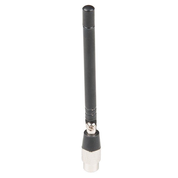
ANT700 from Great Scott Gadgets is a lightweight telescopic antenna designed for operation from 300 MHz to 1100 Hz. Its total length is configurable from 9.5 cm to 24.5 cm. ANT700 is constructed of stainless steel and features an SMA male connector, rotating shaft, and adjustable elbow.
ANT700 is a 50 ohm general purpose antenna. It is a perfect first antenna for use with HackRF One/Pro.
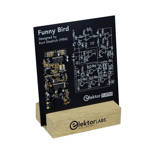
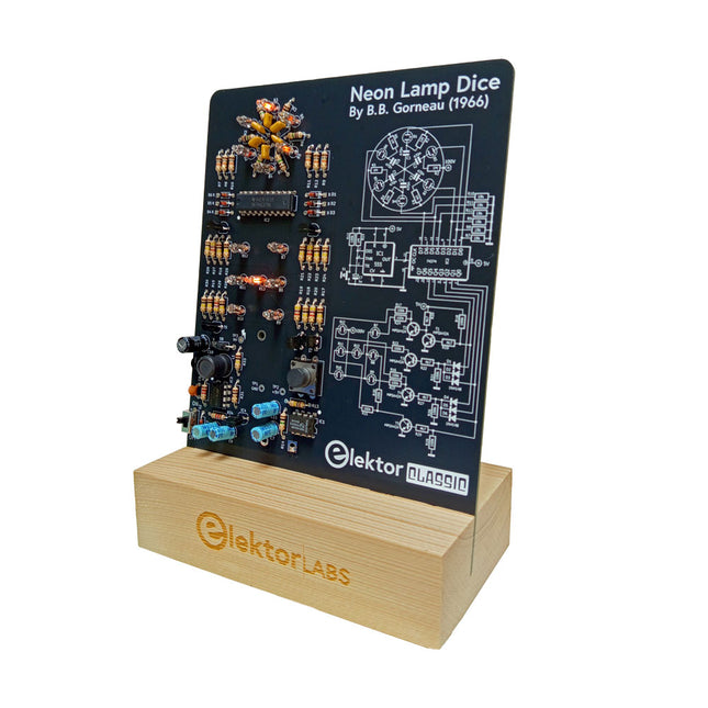
A Retro Roll with a Neon Soul
LED-based dice are common, but their light is cold. Not so for this electronic neon dice, which displays its value with the warm glow of neon lamps. It is perfect for playing games on cold, dark winter evenings. The pips of the dice are neon lamps and the random number generator has six neon lamps to show that it is working.
Even though the dice has an on-board 100-V power supply, it is completely safe. As with all Elektor Classic products, the dice too has its circuit diagram printed on the front while an explanation of how the circuit works can be found on the rear side.
The Neon Lamp Dice comes as a kit of easy-to-solder through-hole parts. The power supply is a 9-V battery (not included).
Features
Warm Vintage Glow
Elektor Heritage Circuit Symbols
Tried & Tested by Elektor Labs
Educational & Geeky Project
Through-Hole Parts Only
Included
Printed Circuit Board
All Components
Wooden Stand
Required
9 V battery
Component List
Resistors (THT, 150 V, 0.25 W)
R1, R2, R3, R4, R5, R6, R14 = 1 MΩ
R7, R8, R9, R10, R11, R12 = 18 kΩ
R13, R15, R16, R17, R18, R21, R23, R24, R25, R26, R28, R30, R33 = 100 kΩ
R32, R34 = 1.2 kΩ
R19, R20, R22, R27, R29 = 4.7 kΩ
R31 = 1 Ω
Capacitors
C1, C2, C3, C4, C5, C6 = 470 nF, 50 V, 5 mm pitch
C7, C9, C11, C12 = 1 µF, 16 V, 2 mm pitch
C8 = 470 pF, 50 V, 5 mm pitch
C10 = 1 µF, 250 V, 2.5 mm pitch
Inductors
L1 = 470 µH
Semiconductors
D1, D2, D3, D4, D5, D6, D7 = 1N4148
D8 = STPS1150
IC1 = NE555
IC2 = 74HC374
IC3 = MC34063
IC4 = 78L05
T1, T2, T3, T4, T5 = MPSA42
T6 = STQ2LN60K3-AP
Miscellaneous
K1 = PP3 9 V battery holder
NE1, NE2, NE3, NE4, NE5, NE6, NE7, NE8, NE9, NE10, NE11, NE12, NE13 = neon light
S2 = Miniature slide switch
S1 = Pushbutton (12 x 12 mm)
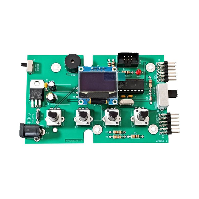
The Elektor Super Servo Tester can control servos and measure servo signals. It can test up to four servo channels at the same time.
The Super Servo Tester comes as a kit. All the parts required to assemble the Super Servo Tester are included in the kit. Assembling the kit requires basic soldering skills. The microcontroller is already programmed.
The Super Servo Tester features two operating modes: Control/Manual and Measure/Inputs.
In Control/Manual mode the Super Servo Tester generates control signals on its outputs for up to four servos or for the flight controller or ESC. The signals are controlled by the four potentiometers.
In Measure/Inputs the Super Servo Tester measures the servo signals connected to its inputs. These signals may come from for instance an ESC, a flight controller, or the receiver or another device. The signals are also routed to the outputs to control the servos or the flight controller or ESC. The results are shown on the display.
Specifications
Operating modes
Control/Manual & Measure/Inputs
Channels
3
Servo signal inputs
4
Servo signal outputs
4
Alarm
Buzzer & LED
Display
0.96' OLED (128 x 32 pixels)
Input voltage on K5
7-12 VDC
Input voltage on K1
5-7.5 VDC
Input current
30 mA (9 VDC on K5, nothing connected to K1 and K2)
Dimensions
113 x 66 x 25 mm
Weight
60 g
Included
Resistors (0.25 W)
R1, R3
1 kΩ, 5%
R2, R4, R5, R6, R7, R9, R10
10 kΩ, 5%
R8
22 Ω, 5%
P1, P2, P3, P4
10 kΩ, lin/B, vertical potentiometer
Capacitors
C1
100 µF 16 V
C2
10 µF 25 V
C3, C4, C7
100 nF
C5, C6
22 pF
Semiconductors
D1
1N5817
D2
LM385Z-2.5
D3
BZX79-C5V1
IC1
7805
IC2
ATmega328P-PU, programmed
LED1
LED, 3 mm, red
T1
2N7000
Miscellaneous
BUZ1
Piezo buzzer with oscillator
K1, K2
2-row, 12-way pinheader, 90°
K5
Barrel jack
K4
1-row, 4-way pin socket
K3
2-row, 6-way boxed pinheader
S1
Slide switch DPDT
S2
Slide switch SPDT
X1
Crystal, 16 MHz
28-way DIP socket for IC2
Elektor PCB
OLED display, 0.96', 128 x 32 pixels, 4-pin I²C interface
Links
Elektor Magazine
Elektor Labs
Learn to Build Intelligent Embedded Systems
Build smarter embedded systems with Arduino UNO Q. This book gives you the tools, knowledge, and confidence to turn ideas into intelligent, working solutions using the Arduino UNO Q platform. Discover how to build intelligent embedded systems with the Arduino UNO Q and AI.
Unlock the full potential of the Arduino UNO Q, a next-generation platform that combines the real-time power of the STM32U585 microcontroller with the flexibility of a Qualcomm Dragonwing QRB2210 microprocessor.
Learn how to rapidly prototype real-world applications using the Arduino IDE for low-level embedded control and Python in Arduino App Lab for high-level development.
Build confidence through hands-on projects that guide you step by step from basic board features to complete working systems.
Explore ready-to-use, AI based Arduino App Lab examples and see how they can jump-start your development and reduce time to deployment.
Step into the world of Edge AI with a clear, practical introduction to Edge Impulse Studio—no prior AI experience required.
Follow a complete, real-world workflow to create a Keyword Spotting AI application, covering data collection, model training, optimization, and on-device inference using the Edge Impulse Studio.
Bridge the gap between embedded systems and machine learning and learn how to bring intelligence directly onto your hardware.
Perfect for embedded engineers, educators, students, and makers looking to stay ahead in AI-enabled product development.
Projects with Thonny-IDE, uPyCraft-IDE, and ESP32
The 'Python' programming language has enjoyed an enormous upswing in recent years. Not least, various single-board systems such as the Raspberry Pi have contributed to its popularity. But Python has also found widespread use in other fields, such as artificial intelligence (AI) or machine learning (ML). It is obvious, therefore, to use Python or the 'MicroPython' variant for use in SoCs (Systems on Chip) as well.
Powerful controllers such as the ESP32 from Espressif Systems offer excellent performance as well as Wi-Fi and Bluetooth functionality at an affordable price. With these features, the Maker scene has been taken by storm. Compared to other controllers, the ESP32 has a significantly larger flash and SRAM memory, as well as a much higher CPU speed. Due to these characteristics, the chip is not only suitable for classic C applications, but also for programming with MicroPython.
This book introduces the application of modern one-chip systems. In addition to the technical background, the focus is on MicroPython itself. After the introduction to the language, the programming skills learned are immediately put into practice. The individual projects are suitable for use in the laboratory as well as for everyday applications. So, in addition to the actual learning effect, the focus is also on the joy of building complete and useful devices. By using laboratory breadboards, circuits of all kinds can be realized with little effort, turning the testing and debugging of the 100% homebrew projects into an instructive pleasure.
The various applications, such as weather stations, digital voltmeters, ultrasound range finders, RFID card readers or function generators, make the projects presented ideally suited for practical courses or subject and study work in the natural sciences, or in science and technology classes.
Example projects with Node-RED, MQTT, WinCC SCADA, Blynk, and ThingSpeak
This comprehensive guide unlocks the power of Modbus TCP/IP communication with Arduino. From the basics of the Modbus protocol right up to full implementation in Arduino projects, the book walks you through the complete process with lucid explanations and practical examples.
Learn how to set up Modbus TCP/IP communication with Arduino for seamless data exchange between devices over a network. Explore different Modbus functions and master reading and writing registers to control your devices remotely. Create Modbus client and server applications to integrate into your Arduino projects, boosting their connectivity and automation level.
With detailed code snippets and illustrations, this guide is perfect for beginners and experienced Arduino enthusiasts alike. Whether you‘re a hobbyist looking to expand your skills or a professional seeking to implement Modbus TCP/IP communication in your projects, this book provides all the knowledge you need to harness the full potential of Modbus with Arduino.
Projects covered in the book:
TCP/IP communication between two Arduino Uno boards
Modbus TCP/IP communication within the Node-RED environment
Combining Arduino, Node-RED, and Blynk IoT cloud
Interfacing Modbus TCP/IP with WinCC SCADA to control sensors
Using MQTT protocol with Ethernet/ESP8266
Connecting to ThingSpeak IoT cloud using Ethernet/ESP8266
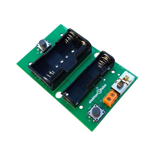
The Elektor Milliohmmeter Adapter uses the precision of a multimeter to measure very low resistance values. It is an adapter that converts a resistance into a voltage that can be measured with a standard multimeter.
The Elektor Milliohmmeter Adapter can measure resistances below 1 mΩ using a 4-wire (Kelvin) method. It is useful for locating short circuits on printed circuit boards (PCB).
The adapter features three measurement ranges – 1 mΩ, 10 mΩ, and 100 mΩ – selectable via a slide switch. It also includes onboard calibration resistors. The Elektor Milliohmmeter Adapter is powered by three 1.5 V AA batteries (not included).
Specifications
Measurement ranges
1 mΩ, 10 mΩ, 100 mΩ, 0.1%
Power supply
3x 1.5 V AA batteries (not included)
Dimensions
103 x 66 x 18 mm (compatible with Hammond 1593N-type enclosure, not included)
Special feature
On-board calibration resistors
Downloads
Documentation
An 8-in-1 test & measurement instrument for the electronics workbench
A well-equipped electronics lab is crammed with power supplies, measuring devices, test equipment and signal generators. Wouldn‘t it be better to have one compact device for almost all tasks? Based on the Arduino, a PC interface is to be developed that’s as versatile as possible for measurement and control. It simply hangs on a USB cable and – depending on the software – forms the measuring head of a digital voltmeter or PC oscilloscope, a signal generator, an adjustable voltage source, a frequency counter, an ohmmeter, a capacitance meter, a characteristic curve recorder, and much more.
The circuits and methods collected here are not only relevant for exactly these tasks in the "MSR" electronics lab, but many details can also be used within completely different contexts.
Resonances From Aether Days
A Pictorial and Technical Analysis from WWII to the Internet Age
From the birth of radio to the late 1980s, much of real life unfolded through shortwave communication. World War II demonstrated—beyond a shadow of a doubt—that effective communications equipment was a vital prerequisite for military success. In the postwar years, shortwave became the backbone on which many of the world's most critical services depended every day.
All the radio equipment—through whose cathodes, grids, plates, and transistors so much of human history has flowed—is an exceptional subject of study and enjoyment for those of us who are passionate about vintage electronics. In this book, which begins in the aftermath of World War II, you’ll find a rich collection of information: descriptions, tips, technical notes, photos, and schematics that will be valuable for anyone interested in restoring—or simply learning about—these extraordinary witnesses to one of the most remarkable eras in technological history.
My hope is that these pages will help preserve this vast treasure of knowledge, innovation, and history—a heritage that far transcends the purely technical.
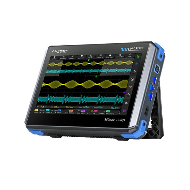
2 Channels • 350 MHz • 1 GSa/s • 50,000 wfm/s • 7 inch Touchscreen
The FNIRSI DPOS350P is a sleek 4-in-1 powerhouse in tablet form! This compact and portable device packs serious functionality: it combines a 2-channel oscilloscope (350 MHz), a signal generator (50 MHz), a frequency response analyzer (50 MHz), and a spectrum analyzer (200 kHz–350 MHz) – all in one unit.
Whether you're in R&D, troubleshooting, or field testing, the DPOS350P delivers the tools you need to measure, generate, analyze, and visualize electronic signals with precision and clarity. Its responsive high-resolution touchscreen and intuitive controls make signal analysis fast, flexible and efficient.
Features
Powerful Multi-Function Integration
350 MHz 2-channel oscilloscope with 1 GSa/s real-time sampling
50 MHz signal generator with 14 standard + custom waveforms
Spectrum analyzer (200 kHz–350 MHz): Perfect for EMI, RF & HF testing
Frequency response analyzer (FRA) up to 50 MHz
High-Performance Waveform Capture
50,000 wfm/s refresh rate for real-time signal clarity
350 MHz bandwidth (single-channel mode)
Detects rare and low-probability anomalies
Crisp Display & Smooth Operation
7" IPS touchscreen (1024 x 600 resolution)
Switch between grayscale and color temperature display
Easy to operate in various test environments
Reliable, Protected & Fast-Charging
High-voltage protection up to 400 V
Fast charging with QC 18 W (full charge in 2 hours)
Built for stable long-term operation
Data Storage & Export
Save up to 500 waveform records + 90 screenshots
USB export for easy reporting and offline analysis
Specifications
General
Display
7 inch (IPS full viewing angle)
Resolution
1024 x 600 pixels
Interaction mode
Capacitive touch screen
Total power consumption
10 W
Power-on configuration
5 presets
Charging
QC 18 W, 12 V/1.5 A (USB-C)
Battery
3.7 V, 8000 mAh lithium battery
Battery life
approx. 3 hours in operation, 5 hours standby
Heat dissipation
Air cooling
Expansion interface
USB data port
Automatic shutdown
15~60 minutes / off
Firmware upgrade
Support .iso image upgrade
Languages
English / Portuguese / Russian / Chinese
Dimensions
190 x 128 x 37 mm
Oscilloscope
Analog channels
2
Analog bandwidth
350 MHz
Rise time
1ns
Real-time sampling rate
1 GSa/s
Memory depth
60 Kpts
Input impedance
1 MΩ / 14PF
Time base range
5ns ~ 50s
Roll time base
50ms ~ 50s
Vertical sensitivity
2 mV ~ 20 V (1X)
Vertical range
16 mV ~ 160 V (1X)
DC accuracy
±2%
Time accuracy
±0.01%
Input coupling
DC / AC
Probe attenuation
1X / 10X / 100X
Hardware bandwidth limit
150M / 20M
High resolution mode
8bit ~ 16bit
Parameter measurements
12 types
Cursor measurement
Time, period, frequency, level, voltage
Trigger detection
Digital trigger
Trigger channel
CH1 / CH2
Trigger mode
Auto / Single / Normal
Trigger edge
Rising edge / Falling edge
Trigger suppression
L1 ~ L3
Trigger level
Manual / automatic 10% ~ 90%
Screenshot storage
90 pictures
Waveform storage
500 groups
Background grid
Display / hide
Waveform movement
Coarse adjustment / fine adjustment
Overvoltage protection
Withstand voltage 400 V
Waveform brightness
Adjustable
Simple FFT display
Yes
Digital fluorescence
Yes
Color temperature display
Yes
X-Y mode
Yes
ZOOM time base
Yes
One-key automatic adjustment
Yes
One-key return to zero
Yes
Data browser
Yes
Signal Generator
Waveform types
14 standard functions + captured waveform
Frequency
0~50 MHz (sine wave only, other waveforms up to 10M/5M/3M)
Amplitude
0~5 VPP
Offset
-2.5 V ~ +2.5V
Duty cycle
0.1~99.9%
Frequency resolution
1 Hz
Amplitude resolution
1 mV
Offset resolution
1 mV
Duty cycle resolution
0.1%
Customizable captured waveform
500 groups
Frequency Response Analyzer (FRA)
Excitation signal frequency
100 Hz ~ 50 MHz
Excitation signal amplitude
0~5 VPP
Excitation signal offset
-2.5V ~ +2.5V
Excitation frequency count
20~500
Cursor measurement
Frequency / gain / phase
Operating mode
Single / cyclic
System calibration
Yes
Spectrum Analyzer
Conversion method
FFT
FFT length
4K ~ 32K
Frequency range
200 KHz ~ 350 MHz
Level range
-60 dBmV ~ +260 dBmV
Cursor measurement
Frequency / amplitude
Marking parameter
Maximum energy harmonic
Waterfall chart
Yes
3D waterfall chart
Yes
Automatic adjustment
Yes
System calibration
Yes
Included
1x FNIRSI DPOS350P Oscilloscope (4-in-1)
2x 350 MHz Probes
1x QC 18 W Fast Charger (EU)
1x USB-C Cable
1x Alligator Clip
1x Storage Bag
1x Manual
Downloads
Manual
Firmware
SD card quality is crucial for a good Raspberry Pi experience. Raspberry Pi's A2 microSD cards support higher bus speeds and command queuing, improving random read performance and narrowing the gap with NVMe SSDs. These cards are rigorously tested for optimal performance with Raspberry Pi models.
Features
Capacity: 64 GB
Support for DDR50 and SDR104 bus speeds and command queueing (CQ) extension
Speed Class: C10, U3, V30, A2
Random 4 KB read performance: 3,200 IOPS (Raspberry Pi 4, DDR50) 5,000 IOPS (Raspberry Pi 5, SDR104)
Random 4 K write performance: 1,200 IOPS (Raspberry Pi 4, DDR50) 2,000 IOPS (Raspberry Pi 5, SDR104)
Shock-proof, X-ray–proof, and magnet-proof
microSDHC/microSDXC formats
Downloads
Datasheets
From Simple Ciphers to Secure Systems
Understanding how to apply cryptography on modern microcontrollers is essential for building secure, reliable, and trustworthy systems. This book explains cryptography in the context of embedded hardware, from classical ciphers that illustrate core principles to modern techniques such as AES for practical high-security applications.
By combining mathematical theory with real-world microcontroller implementations, readers learn not only how cryptography works, but also how to implement it effectively on systems with limited processing power and memory. The book is intended for students starting out in cryptography, hobbyists securing personal projects, and engineers looking for a structured guide to embedded security.
The book covers these key topics in applied cryptography:
Classical ciphers on Arduino Uno and Raspberry Pi Pico, with full programs: Spartan Scytale, Hebrew Atbash, Caesar, ROT13, Alberti Disk, Vigenère, Affine, Polybius, Playfair, Beaufort, Ottoman Codebook, and One-Time Pad.
Hacking classical ciphers using microcontrollers, with examples.
Pseudo-random (PRNG) and true random number generation (TRNG) on microcontrollers.
Symmetric-key cryptography with full programs: DES and AES-128/256.
Memory and speed constraints of cryptography on microcontrollers.
Asymmetric cryptography: public/private keys, digital signatures, key distribution and derivation (KDF), RSA, and SHA-256 implementations.
A complete secure communication program using RSA and AES-256.
A glossary of commonly used cryptography terms.
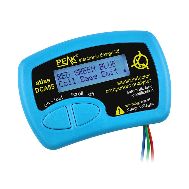
The Peak Atlas DCA55 is great for automatically identifying the type of semiconductor on the test leads as well as the pinout and many other parameters.
Supports transistors MOSFETs, JFETs (gate pin only can be identified), diodes, LEDs and lots more. Automatically identifies type of component, pinout and other important parameters. Now features transistor leakage measurement and Germanium/Silicon identification.
Component Support
Bipolar transistors (NPN/PNP inc Silicon/Germanium)
Darlington transistors (NPN/PNP)
Enhancement mode MOSFETs (N-Ch and P-Ch)
Depletion mode MOSFETs (N-Ch and P-Ch)
Junction FETs (N-Ch and P-Ch). Only gate lead identified
Diodes and diode networks (2 and 3 lead types)
LEDs and bi-colour LEDs (2 lead and 3 lead types)
Low power sensitive Triacs and Thyristors (<5 mA trigger and hold)
Measurements
Part type identification
Pinout identification
BJT current gain (hFE)
BJT base emitter voltage (Vbe)
BJT collector leakage current
MOSFET gate threshold voltage
Diode forward voltage drop (Vf)
Specifications
Analyzer type
Transistors, Diodes, LEDs, MOSFETs, JFETs
Pinout detection
Full pinout (only Gate on JFETs)
Pinout configuration
Connect any way round
Transistor measurements
Vbe, hFE, Iceo
MOSFET measurements
Vgs(on)
Diode measurements
Vf
Probe type
Universal grabber type
Battery
Single AAA cell (supplied). Life typically 1300 ops
Test conditions
Typically 5 mA, 5 V peak
Display type
Alphanumeric LCD (with backlight)
Included
Peak Atlas DCA55 Semiconductor Analyzer
Comprehensive illustrated user guide
Fitted universal hook probes
AAA Alkaline battery
Downloads
Datasheet (EN)
User Guide (EN)
User Guide (IT)
Kick off with the MAX1000 and VHDPlus
Ready to Master FPGA Programming? In this guide, we’re diving into the world of Field Programmable Gate Arrays (FPGAs) – a configurable integrated circuit that can be programmed after manufacturing. Imagine bringing your ideas to life, from simple projects to complete microcontroller systems!
Meet the MAX1000: a compact and budget-friendly FPGA development board packed with features like memory, user LEDs, push-buttons, and flexible I/O ports. It’s the ideal starting point for anyone wanting to learn about FPGAs and Hardware Description Languages (HDLs).
In this book, you’ll get hands-on with the VHDPlus programming language – a simpler version of VHDL. We’ll work on practical projects using the MAX1000, helping you gain the skills and confidence to unleash your creativity.
Get ready for an exciting journey! You’ll explore a variety of projects that highlight the true power of FPGAs. Let’s turn your ideas into reality and embark on your FPGA adventure – your journey starts now!
Exciting Projects You’ll Find in This Book
Arduino-Driven BCD to 7-Segment Display Decoder
Use an Arduino Uno R4 to supply BCD data to the decoder, counting from 0 to 9 with a one-second delay
Multiplexed 4-Digit Event Counter
Create an event counter that displays the total count on a 4-digit display, incrementing with each button press
PWM Waveform with Fixed Duty Cycle
Generate a PWM waveform at 1 kHz with a fixed duty cycle of 50%
Ultrasonic Distance Measurement
Measure distances using an ultrasonic sensor, displaying the results on a 4-digit 7-segment LED
Electronic Lock
Build a simple electronic lock using combinational logic gates with push buttons and an LED output
Temperature Sensor
Monitor ambient temperature with a TMP36 sensor and display the readings on a 7-segment LED
Downloads
Software
Understanding and Using Them Effectively
What happens in electronics is invisible to the naked eye. The instrument that allows to accurately visualize electrical signals, the one through which the effects of electronics become apparent to us, is the oscilloscope.
Alas, when one first ventures into electronics, it is often without an oscilloscope. And one is left fumbling, both physically and mentally. Observing an electrical signal on a screen for the first time is a revelation. Nobody wishes to forgo that marvel again. There is no turning back.
In electronics, if one wishes to progress with both enjoyment and understanding, an oscilloscope is essential. This marks the beginning of a period of questioning: how to choose one? And no sooner is that question answered than a whole string of others arises, which can be summed up in just one: how does one use the oscilloscope in such a way that what it displays truly reflects the reality of the signals?
Rémy Mallard is a passionate communicator with a gift for making complex technical subjects understandable and engaging. In this book, he provides clear answers to essential questions about using an oscilloscope and offers a wealth of guidance to help readers explore and understand the electrical signals behind electronic systems. With his accessible style and practical insights, this book is a valuable tool for anyone eager to deepen their understanding of electronics.