NEW
-

Elektor Publishing High-End Tube Amplifier Design
A Toolbox for Audio Lovers and Engineers Without any ambition to reach scientific levels, this book aims to be a toolbox for both audio lovers and high-end equipment designers. The elementary theory presented is the bare minimum for readers to grasp the operation and practical use of electrical, electromagnetic, physics, and electronic operations available in the designers’ toolbox. Each tool is explained in a minimum of words and theory without needless coverage of underlying equations or figures. The book chapters guide you through the process of designing quality amplifiers with vacuum tubes, from the very beginning, considering both technical and subjective requirements – in theory and practice. The book is a compilation of the author’s notes used in his professional and educational career but was nevertheless primarily written as a result of true love for the audiophile hobby.
€ 69,95
Members: € 62,96
-

Elektor Publishing Object-Oriented PLC Programming in CODESYS
Modular and Scalable Control Systems Using Structured Text This book offers a structured and practical approach to modern PLC development using object-oriented principles. It is a guide for engineers, programmers, and students seeking to harness the power of object-oriented programming (OOP) in the context of industrial automation with PLCs. The content focuses on the CODESYS development environment and Structured Text (ST), both of which support modern programming techniques while maintaining compatibility with real-time automation requirements. Through step-by-step demos and instructional examples, it demonstrates how modular, reusable code can enhance development efficiency, simplify ongoing maintenance, and enable scalable and flexible control system architectures. Key topics include: Structured Text fundamentals: conditions, loops, arrays, and functions Object-oriented concepts: classes, methods, and inheritance Advanced techniques: polymorphism, interfaces, and access control Modular design with reusable components and structured program flow Implementation of finite state machines and scalable application design Built around instructional demos and clear explanations, this book helps readers develop maintainable and modern control software in the CODESYS environment using proven programming techniques.
€ 34,95
Members: € 31,46
-

Elektor Circuit Special 2025 (EN)
Elektor GREEN and GOLD members can download their digital edition here. Not a member yet? Click here. USB Measurement AdapterTesting Current and Signal Quality of USB Ports 4...20 mA Current Output for Arduino UnoA Reliable, EMI-Insensitive Current Loop Interface Vacuum Cleaner Automatic ControlKeep Your Tools’ Work Area Clean DDS Generator with ATtiny Opamp-Tester V2New PCB – Now Also Suitable for SMDs 550-mW “Lamp” Audio AmplifierGet the Warm Sound of Vacuum Tubes With Ease Fuse GuardMonitoring a Fuse with a Flashing LED HQ RIAA PreamplifierGet the Most Out of Your Vinyl Records! Turntable Speed CalibratorAn Arduino-Based 100–120 Hz Strobe Light Generator Elektor Classics: video buffer/repeater Infrared Remote-Controlled DimmerControl Your Halogen or LED Floor Lamp Effortlessly and With Style How to Use switch…case on Strings in C++/Arduino IDE Magnet FinderWith a Simple Hall-Effect Sensor Raspberry Pi Smart Power ButtonA Solution for Raspberry Pi Up to Model 4 Essential Maker TipsProfessional Insights for Everyday Making Practical Projects with the 555 TimerDC Motor Control and Fast Reaction Challenges Basic AC-Load-On MonitorSave Energy with a Simple Device Power Banks in ParallelA Three-Day Continuous Power Solution VFO Up to 15 MHzAn Implementation With Raspberry Pi Pico Violin Tuner with ATtiny202 Elektor Classics: video amplifier for B/W television sets Capacitance Meter20 pF to 600 nF Quasi-Analog Clockwork Mk IITwo LED Rings for Hours and Minutes You Can Do Anything You Want(with the Arduino Ecosystem at Your Side) Neon Lamp Dice Elektor Classics: RTTY calibrator indicator Inspiring Hardware Designs for Your ESPs Elektor Classics: variable 3 A power supply RGB LEDs with Integrated Control CircuitLight with Precision: ICLEDs Set Standards Experiment: Towards a Mixed-Signal Theremin?Blending Modern Time-of-Flight Sensors With the Timeless XR2206 Analog Generator ESP32 Audio Transceiver Board (Part 1)SD Card WAV File Player Demo Infographics: Circuits and Circuit Design 2025 Small Audio MixerA Simple and Versatile Scalable Design Smart Staircase Light TimerSave More Money on the Energy Bill! Smarten Up Your ShuttersControlling Velux Hardware With an ESP32 and MQTT Solid-State Foot WarmerEnergy-Efficient Comfort Is the M5Stamp Fly Quadcopter the Next Tello? Boosting Wi-Fi Range of the ESP32-C3 SuperMiniA Simple and Effective Antenna Mod ZD-8968 Hot-Air Soldering StationA Budget-Friendly Workhorse or Just Hot Air? Parking Sensor TesterFinding Defects in the PDC System of a Car
€ 14,90
-

Elektor Labs Elektor AM Transmitter Kit
Build Your Own Vintage Radio Broadcaster The Elektor AM Transmitter Kit allows streaming audio to vintage AM radio receivers. Based on a Raspberry Pi Pico microcontroller module, the AM Transmitter can transmit on 32 frequencies in the AM band, from 500 kHz up to 1.6 MHz in 32 steps of approx. 35 kHz. The frequency is selected with a potentiometer and shown on a 0.96" OLED display. A pushbutton allows toggles the transmitting mode between On and Off. The range of the transmitter depends on the antenna. The onboard antenna provides a range of a few centimeters, requiring the AM Transmitter to be placed close to or inside the radio. An external loop antenna (not included) can be connected to increase the range. The Elektor AM Transmitter Kit comes as a kit of parts that you must solder to the board yourself. Features The board is compatible with a Hammond 1593N enclosure (not included).A 5 VDC power supply with micro-USB connector (e.g., an old phone charger) is needed to power the kit (not included). Current consumption is 100 mA. The Arduino software (requiring Earle Philhower’s RP2040 Boards Package) for the Elektor AM Transmitter Kit plus more information is available at the Elektor Labs page of this project. Component List Resistors R1, R4 = 100 Ω R2, R3, R8 = 10 kΩ R5, R6, R9, R10, R11 = 1 kΩ R7 = optional (not included) P1 = potentiometer 100 kΩ, linear Capacitors C1 = 22 µF 16V C2, C4 = 10 nF C3 = 150 pF Miscellaneous K1 = 4×1 pin socket K2, K3 = 3.5 mm socket Raspberry Pi Pico pushbutton, angle mount 0.96" monochrome I²C OLED display PCB 150292-1
€ 34,95€ 29,95Best Price
-

Elektor Bundles The ESP32 Cheap Yellow Display Bundle
Over 40 Fully Tested ESP32 Projects Using Arduino IDE and the LVGL Graphics Library This bundle includes the ESP32 Cheap Yellow Display (CYD) – a compact development board combining a standard ESP32 microcontroller with a 320x240 pixel TFT color display. The board also features multiple connectors for GPIO, serial communication (TX/RX), power, and ground. The built-in display is a major advantage, allowing users to create complex, graphics-based projects without the need for external LCDs or displays. The accompanying book introduces the CYD board's hardware and on-board connectors in detail. It provides a range of beginner to intermediate-level projects developed using the popular Arduino IDE 2.0. Both basic graphics functions and the powerful LVGL graphics library are covered, with practical projects illustrating each approach. All included projects have been fully tested and are ready to use. The book provides block diagrams, circuit schematics, complete code listings, and step-by-step explanations. With the LVGL library, readers can create modern, full-color graphical interfaces using widgets such as buttons, labels, sliders, calendars, keyboards, charts, tables, menus, animations, and more. ESP32 Cheap Yellow Display Board This development board (also known as "Cheap Yellow Display") is powered by the ESP-WROOM-32, a dual-core MCU with integrated Wi-Fi and Bluetooth capabilities. It operates at a main frequency of up to 240 MHz, with 520 KB SRAM, 448 KBROM, and a 4 MB Flash memory. The board features a 2.8-inch display with a resolution of 240x320 and resistive touch. Furthermore, the board includes a backlight control circuit, touch control circuit, speaker drive circuit, photosensitive circuit, and RGB-LED control circuit. It also provides a TF card slot, serial interface, DHT11 temperature and humidity sensor interface, and additional IO ports. The module supports development in Arduino IDE, ESP-IDE, MicroPython, and Mixly. Applications Image transmission for Smart Home device Wireless monitoring Smart agriculture QR wireless recognition Wireless positioning system signal And other IoT applications Specifications Microcontroller ESP-WROOM-32 (Dual-core MCU with integrated Wi-Fi and Bluetooth) Frequency Up to 240 MHz (computing power is up to 600 DMIPS) SRAM 520 KB ROM 448 KB Flash 4 MB Operating voltage 5 V Power consumption approx. 115 mA Display 2.8-inch color TFT screen (240 x 320) Touch Resistive Touch Driver chip ILI9341 Dimensions 50 x 86 mm Weight 50 g Downloads GitHub This bundle contains: The ESP32 Cheap Yellow Display Book (normal price: €35) ESP32 Cheap Yellow Display Board (normal price: €25) 1x ESP32 Dev Board with 2.8" Display and acrylic Shell 1x Touch pen 1x Connector cable 1x USB cable
€ 59,95€ 49,95Best Price
-

Elektor Publishing The ESP32 Cheap Yellow Display Book
Projects Using Arduino IDE and the LVGL Graphics Library The ESP32 is probably one of the most popular microcontrollers used by many people, including students, hobbyists, and professional engineers. Its low cost, coupled with rich features makes it a popular device to use in many projects. Recently, a board called the ESP32 Cheap Yellow Display (CYD for short) is available from its manufacturers. The board includes a standard ESP32 microcontroller together with a 320x240 pixel TFT display. Additionally, the board provides several connectors for interfaces such as GPIO, serial port (TX/RX), power and Ground. The inclusion of a TFT display is a real advantage as it enables users to design complex graphics-based projects without resorting to an external LCD or graphics displays. The book describes the basic hardware of the ESP32 CYD board and provides details of its on-board connectors. Many basic, simple, and intermediate-level projects are given in the book based on the ESP32 CYD, using the highly popular Arduino IDE 2.0 integrated development environment. The use of both the basic graphics functions and the use of the popular LVGL graphics library are discussed in the book and projects are given that use both types of approaches. All the projects given in the book have been tested and are working. The block diagram, circuit diagram, and the complete program listings and program descriptions of all the projects are given with explanations. Readers can use the LVGL graphics library to design highly popular eye-catching full-color graphics projects using widgets such as buttons, labels, calendars, keypads, keyboards, message boxes, spinboxes, sliders, charts, tables, menus, bars, switches, drop-down lists, animations, and many more widgets.
€ 34,95
Members: € 31,46
-

Elektor July/August 2025 (EN)
Elektor GREEN and GOLD members can download their digital edition here. Not a member yet? Click here. OBD2 Sensor DashboardOld Dials Sparked a Quest for Real Data OBD2: Add a Rev Counter and Gear Shift Indicator to Your CarRetro, but Super Useful LiDAR and Vision Sensors for Robotics Sensor+Test 2025 and PCIM 2025 Contact-Free E-Field Measurements (1)A Vibrating Membrane for Assessing DC Voltages or Static Electric Fields Wireless Mailbox NotifierFrom Optical Sensors to Radar, Exploring a Few Options Elektor Mini-WheelieA Self-Balancing Robot Solar CellsPeculiar Parts, the Series Getting Started With a Modern Radar SensorIs an Accurate Measurement on Your Radar? From Life’s ExperiencePaper Factory CybersecurityTough Times for Hackers Siglent Presents Next-Gen Multi-Channel OscilloscopesHigh-Performance Solutions for Modern Power and Embedded Systems Bluetooth 6.0 Brings Enhanced Distance-Ranging ApplicationsNew Version Offers Improved Device Positioning and Location Services Exploring Wireless Communication with BeagleY-AI Err-lectronicsCorrections, Updates, and Readers’ Letters Starting Out in Electronics……Concludes the Topic on Opamps A Powerful AI Code AssistantSpeed Up Your Development with Continue and Visual Studio Code Solar Charge Controller with MPPT (2)The Circuit Ultrasonic Obstacle DetectorA Simple Project to Help Those with Impaired Vision 2025: An AI OdysseyMid-Year Review Raspberry Pi Standalone MIDI Synthesizer (3)Making It Smarter and Adding a User Interface Meshtastic: A Demo ProjectAn Intelligent Mesh of LoRa Radios Analog Audio Frequency GeneratorHigh-Quality Adjustable Frequency Sine Wave Generator
€ 10,95
-

Elektor Digital Elektor Select: Embedded & AI (PDF)
This collection features the best of Elektor Magazine's articles on embedded systems and artificial intelligence. From hands-on programming guides to innovative AI experiments, these pieces offer valuable insights and practical knowledge for engineers, developers, and enthusiasts exploring the evolving intersection of hardware design, software innovation, and intelligent technology. Contents Programming PICs from the Ground UpAssembler routine to output a sine wave Object-Oriented ProgrammingA Short Primer Using C++ Programming an FPGA Tracking Down Microcontroller Buffer Overflows with 0xDEADBEEF Too Quick to Code and Too Slow to Test? Understanding the Neurons in Neural NetworksEmbedded Neurons MAUI Programming for PC, Tablet, and SmartphoneThe New Framework in Theory and Practice USB Killer DetectorBetter Safe Than Sorry Understanding the Neurons in Neural NetworksArtificial Neurons A Bare-Metal Programming Guide Part 1: For STM32 and Other Controllers Part 2: Accurate Timing, the UART, and Debugging Part 3: CMSIS Headers, Automatic Testing, and a Web Server Introduction to TinyMLBig Is Not Always Better Microprocessors for Embedded SystemsPeculiar Parts, the Series FPGAs for BeginnersThe Path From MCU to FPGA Programming AI in Electronics DevelopmentAn Update After Only One Year AI in the Electronics LabGoogle Bard and Flux Copilot Put to the Test ESP32 and ChatGPTOn the Way to a Self-Programming System… Audio DSP FX Processor Board Part 1: Features and Design Part 2: Creating Applications Rust + EmbeddedA Development Power Duo A Smart Object CounterImage Recognition Made Easy with Edge Impulse Universal Garden LoggerA Step Towards AI Gardening A VHDL ClockMade with ChatGPT TensorFlow Lite on Small MicrocontrollersA (Very) Beginner’s Point of View Mosquito DetectionUsing Open Datasets and Arduino Nicla Vision Artificial Intelligence Timeline Intro to AI AlgorithmsPrompt: Which Algorithms Implement Each AI Tool? Bringing AI to the Edgewith ESP32-P4 The Growing Role of Edge AIA Trend Shaping the Future
€ 9,95
Members: € 8,96
-

Elektor Publishing Mastering FPGA Chip Design
For Speed, Area, Power, and Reliability This book teaches the fundamentals of FPGA operation, covering basic CMOS transistor theory to designing digital FPGA chips using LUTs, flip-flops, and embedded memories. Ideal for electrical engineers aiming to design large digital chips using FPGA technology. Discover: The inner workings of FPGA architecture and functionality. Hardware Description Languages (HDL) like Verilog and VHDL. The EDA tool flow for converting HDL source into a functional FPGA chip design. Insider tips for reliable, low power, and high performance FPGA designs. Example designs include: Computer-to-FPGA UART serial communication. An open-source Sump3 logic analyzer implementation. A fully functional graphics controller. What you need: Digilent BASYS3 or similar FPGA eval board with an AMD/Xilinx FPGA. Vivado EDA tool suite (available for download from AMD website free of charge). Project source files available from author’s GitHub site.
€ 39,95
Members: € 35,96
-

Elektor Special: Sensors for Weather and the Environment
Build your textbook weather station or conduct environmental research together with the whole world. With many practical projects for Arduino, Raspberry Pi, NodeMCU, ESP32, and other development boards. Weather stations have enjoyed great popularity for decades. Every current and even every long discontinued electronics magazine has regularly featured articles on building your own weather station. Over the years, they have become increasingly sophisticated and can now be fully integrated into an automated home — although this often requires loyalty to an (expensive) brand manufacturer across all components. With your own weather and environmental data, you can keep up and measure things that no commercial station can. It’s also fun: expand your knowledge of electronics, current microcontroller development boards and programming languages in a fun and meaningful way. For less than 10 euros you can get started and record your first environmental data — with time and growing interest, you will continue to expand your system. In this Edition Which Microcontroller Fits My Project? The Right Development Environment Tracking Wind and Weather Weather Display with OpenWeatherMap and Vacuum Fluorescent Display Volatile Organic Compounds in the Air We Breathe Working with MQ Sensors: Measuring Carbon Monoxide — Odorless but Toxic CO2 Traffic Light with ThingSpeak IoT Connection An Automatic Plant Watering System Good Indoor Climate: Temperature and Humidity are Important criteria Classy Thermometer with Vintage Tube Technology Nostalgic Weather House for the Whole Family Measuring Air Pressure and Temperature Accurately Sunburn Warning Device DIY Sensor for Sunshine Duration Simple Smartphone Says: Fog or Clear View? Identifying Earthquakes Liquid Level Measurement for Vessels and Reservoirs Water pH Value Measurement Detecting Radioactive Radiation GPS: Sensor Location Service Across the Globe Saving and Timestamping Log Files on SD Cards LoRaWAN, The Things Network, and ThingSpeak Operating a LoRaWAN Gateway for TTN Defying "Wind and Weather" Mega Display with Weather Forecasz
€ 19,95
Members: € 17,96
-

Elektor Publishing ESP32 by Example
A Project-Based Introduction to Microcontrollers and Drone Control A Practical Introduction to Embedded Systems with the ESP32 This book is intended for readers who are new to embedded systems and looking for a structured, example-driven way to begin. If you’ve explored general-purpose electronics or Arduino-based resources but found them too broad or lacking in practical application, this guide offers a more focused alternative. With a small, affordable set of components – such as LEDs, sensors, an OLED screen and a motion sensor – you’ll build and work with the same hardware setup throughout the book. This allows you to focus on learning and experimenting without constant reconfiguration. Topics include: Understanding and programming the ESP32 microcontroller Using the Arduino IDE to write and deploy code Exploring cyber-physical systems, culminating in basic drone control No prior experience with Arduino or embedded development is required. Each section includes hands-on examples and mini-projects designed to reinforce core concepts and encourage deeper exploration. By the end, you’ll be equipped not only to reproduce the book’s examples, but also to extend them toward your own ideas and applications. Whether your interest is in learning embedded programming, building interactive systems, or exploring educational drone control, this book provides a clear and practical path to getting started.
€ 44,95
Members: € 40,46
-

Elektor Publishing How Humanity Turned Electricity into Electronics
From Rubbing Amber to Swiping Glass "The story of electricity, told one connection at a time."Why does rubbing amber attract dust? How did we go from that curious effect to a world where screens respond to a single touch? And how did we get from mysterious sparks to tiny chips packed with billions of transistors? For centuries, electricity puzzled and fascinated those who encountered its curious effects—long before it even had a name. From the earliest observations of static charge to the complex electronics that shape our lives today, this book traces the gradual, and often surprising, story of how humanity came to understand and harness this powerful force. This book offers an engaging and accessible account of the people, ideas, and inventions that transformed electricity from a scientific curiosity into the foundation of our digital age. Along the way, you’ll meet a host of inquisitive minds—some famous, others less so—whose persistence and creativity helped unravel the mysteries of the natural world and gave rise to the technologies we now take for granted. Covering everything from Leyden jars and batteries to transistors, microcontrollers and the internet, this book presents a clear and enjoyable overview of electronics and its relatively short, yet rich, history. Whether you have a technical background or simply a curiosity about how things work, From Rubbing Amber to Swiping Glass offers a thoughtful look at how far we’ve come—and a gentle nudge to wonder what might come next.
€ 39,95
Members: € 35,96
-
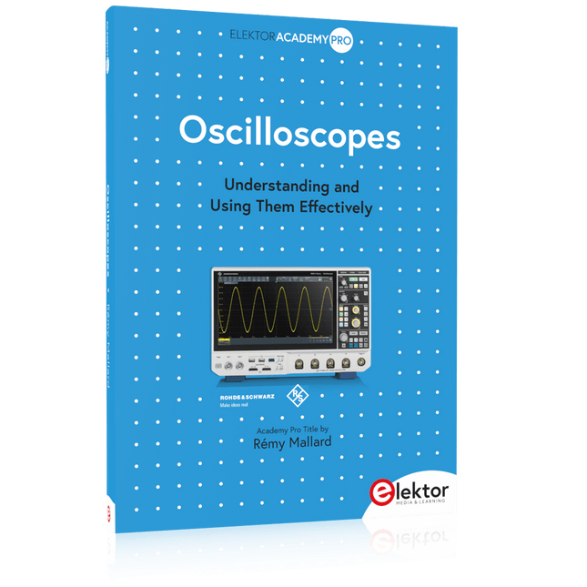
Elektor Publishing Oscilloscopes (Book)
Understanding and Using Them Effectively What happens in electronics is invisible to the naked eye. The instrument that allows to accurately visualize electrical signals, the one through which the effects of electronics become apparent to us, is the oscilloscope. Alas, when one first ventures into electronics, it is often without an oscilloscope. And one is left fumbling, both physically and mentally. Observing an electrical signal on a screen for the first time is a revelation. Nobody wishes to forgo that marvel again. There is no turning back. In electronics, if one wishes to progress with both enjoyment and understanding, an oscilloscope is essential. This marks the beginning of a period of questioning: how to choose one? And no sooner is that question answered than a whole string of others arises, which can be summed up in just one: how does one use the oscilloscope in such a way that what it displays truly reflects the reality of the signals? Rémy Mallard is a passionate communicator with a gift for making complex technical subjects understandable and engaging. In this book, he provides clear answers to essential questions about using an oscilloscope and offers a wealth of guidance to help readers explore and understand the electrical signals behind electronic systems. With his accessible style and practical insights, this book is a valuable tool for anyone eager to deepen their understanding of electronics.
€ 44,95
Members: € 40,46
-

Elektor May/June 2025 (EN)
Elektor GREEN and GOLD members can download their digital edition here. Not a member yet? Click here. PbMonitor v1.0A Battery-Monitoring System for UPS and Energy Storage Applications Solar Charge Controller with MPPT (1)Basic Principles of a Solar Controller for Stand-Alone Systems B-Field Integration Magnetometer With Home-Made Sensors Precise or Accurate?Your Instruments Need to Be Both! AD7124 A Precision ADC in PracticeFeatures for Sensor Signal Conditioning PID Control ToolOptimize Your Parameters Easily embedded world 2025 Starting Out in Electronics……Continues with Tone Control Academy Pro BoxBook + Online Course + Hardware Milliohmmeter AdapterUses the Precision of Your Multimeter The Next Leap in SemiconductorsOnward Toward 1.4 nm Through-Hole Technology ConnectorsThe Best of Two Worlds: THR Frequency CounterPortable and Auto-Calibrating Via GPS Analog MetersPeculiar Parts, the Series Stand-Alone Crystal TesterHow Accurate Is Your Clock Source? Low-Cost I²C TesterConnect I²C Devices Directly to Your PC From Life’s ExperienceWho Doesn’t Honor the Small Things? 2025: An AI OdysseyThe Transformative Impact on Software Development Err-lectronicsCorrections, Updates, and Readers’ Letters Raspberry Pi Standalone MIDI Synthesizer (2)Enhancing Our Setup with Intelligence Nortonized Wien Bridge OscillatorSmall Changes Yield Significant Improvements Putting a $0.10 Controller to the TestThe CH32V003 RISC-V Microcontroller and MounRiver Studio in Practice An FPGA-Based Audio Player with Equalizer (2)Adding Volume Control, Advanced Mixing, and a Web Interface
€ 10,95
-

Elektor Publishing Vintage Radio Equipment
Resonances From Aether Days A Pictorial and Technical Analysis from WWII to the Internet Age From the birth of radio to the late 1980s, much of real life unfolded through shortwave communication. World War II demonstrated—beyond a shadow of a doubt—that effective communications equipment was a vital prerequisite for military success. In the postwar years, shortwave became the backbone on which many of the world's most critical services depended every day. All the radio equipment—through whose cathodes, grids, plates, and transistors so much of human history has flowed—is an exceptional subject of study and enjoyment for those of us who are passionate about vintage electronics. In this book, which begins in the aftermath of World War II, you’ll find a rich collection of information: descriptions, tips, technical notes, photos, and schematics that will be valuable for anyone interested in restoring—or simply learning about—these extraordinary witnesses to one of the most remarkable eras in technological history. My hope is that these pages will help preserve this vast treasure of knowledge, innovation, and history—a heritage that far transcends the purely technical.
€ 79,95
Members: € 71,96
-

Elektor Publishing Wireless Power Design
From Theory to Practical Applications in Wireless Energy Transfer and Harvesting Wireless power transmission has gained significant global interest, particularly with the rise of electric vehicles and the Internet of Things (IoT). It’s a technology that allows the transfer of electricity without physical connections, offering solutions for everything from powering small devices over short distances to long-range energy transmission for more complex systems. Wireless Power Design provides a balanced mix of theoretical knowledge and practical insights, helping you explore the potential of wireless energy transfer and harvesting technologies. The book presents a series of hands-on projects that cover various aspects of wireless power systems, each accompanied by detailed explanations and parameter listings. The following five projects guide you through key areas of wireless power: Project 1: Wireless Powering of Advanced IoT Devices Project 2: Wireless Powered Devices on the Frontline – The Future and Challenges Project 3: Wireless Powering of Devices Using Inductive Technology Project 4: Wireless Power Transmission for IoT Devices Project 5: Charging Robot Crawler Inside the Pipeline These projects explore different aspects of wireless power, from inductive charging to wireless energy transmission, offering practical solutions for real-world applications. The book includes projects that use simulation tools like CST Microwave Studio and Keysight ADS for design and analysis, with a focus on practical design considerations and real-world implementation techniques.
€ 39,95
Members: € 35,96
-

Elektor Bundles Universal Maker Sensor Bundle
Over 180 Projects with Raspberry Pi, Pico W, Arduino, and ESP32 This bundle contains the Universal Maker Sensor Kit, which consists of many sensors, actuators, displays, and motors. It’s perfect for environmental monitoring, smart home projects, robotics, and game controllers. The new Elektor book describes the design of many projects using the kit together with the popular Raspberry Pi, Raspberry Pi Pico W, Arduino Uno, and the ESP32 family of development boards. You can choose any of these development boards for your projects and either use the provided programs as they are, or modify these programs to suit your applications. This bundle contains: Book: Universal Maker Sensor Kit (normal price: €45) Universal Maker Sensor Kit for Raspberry Pi, Pico W, Arduino, ESP32 (normal price: €70) Book: Universal Maker Sensor Kit Learn to use more than 35 Sensors and Actuators with C++, Python, and MicroPython This book contains over 180 projects for all four major development boards (Arduino, Raspberry Pi, Pico W, and ESP32). Depending on the development board, projects are available in the C, Python, or MicroPython programming languages. The project titles, brief descriptions, wiring diagrams, and full program listings together with their detailed descriptions are given in the guide. Universal Maker Sensor Kit (for Raspberry Pi, Pico W, Arduino, ESP32) Discover endless creativity with the Universal Maker Sensor Kit, designed for use with Raspberry Pi, Pico W, Arduino, and ESP32. This versatile kit offers compatibility across popular development platforms, including Arduino Uno R4 Minima/WiFi, Uno R3, Mega 2560, Raspberry Pi 5, 4, 3B+, 3B, Zero, Pico W, and ESP32. Featuring over 35 sensors, actuators, and displays, it's perfect for projects ranging from environmental monitoring and smart home automation to robotics and interactive gaming. Step-by-step tutorials in C/C++, Python, and MicroPython guide beginners and experienced makers alike through 169 exciting projects. Features Wide Compatibility: Fully supports Arduino (Uno R3, Uno R4 Minima/WiFi, Mega 2560), Raspberry Pi (5, 4, 3B+, 3B, Zero, Pico W), and ESP32, enabling extensive flexibility across numerous development platforms. Includes instructions for building 169 projects. Comprehensive Components: Features more than 35 sensors, actuators, and display modules suitable for diverse projects such as environmental monitoring, smart home automation, robotics, and interactive game controllers. Detailed Tutorials: Provides clear, step-by-step tutorials covering Arduino, Raspberry Pi, Pico W, ESP32, and each included component. Tutorials are available in C/C++, Python, and MicroPython, catering effectively to both beginners and experienced makers. Suitable for All Skill Levels: Offers structured projects designed to guide users seamlessly from beginner to advanced proficiency in electronics and programming, enhancing creativity and technical expertise. Kit includes Breadboard Button Module Capacitive Soil Moisture Module Flame Sensor Module Gas/Smoke Sensor Module (MQ2) Gyroscope & Accelerometer Module (MPU6050) Hall Sensor Module Infrared Speed Sensor Module IR Obstacle Avoidance Sensor Module Joystick Module PCF8591 ADC DAC Converter Module Photoresistor Module PIR Motion Module (HC-SR501) Potentiometer Module Pulse Oximeter and Heart Rate Sensor Module (MAX30102) Raindrop Detection Module Real Time Clock Module (DS1302) Rotary Encoder Module Temperature Sensor Module (DS18B20) Temperature and Humidity Sensor Module (DHT11) Temperature, Humidity & Pressure Sensor (BMP280) Time of Flight Micro-LIDAR Distance Sensor (VL53L0X) Touch Sensor Module Ultrasonic Sensor Module (HC-SR04) Vibration Sensor Module (SW-420) Water Level Sensor Module I²C LCD 1602 OLED Display Module (SSD1306) RGB LED Module Traffic Light Module 5 V Relay Module Centrifugal Pump L9110 Motor Driver Module Passive Buzzer Module Servo Motor (SG90) TT Motor ESP8266 Module JDY-31 Bluetooth Module Power Supply Module Documentation Online Tutorial
€ 114,95€ 94,95Best Price
-
Unitree Unitree Go2 Remote Controller
The Unitree Go2 Controller is a dedicated remote control device designed for seamless and precise operation of the Unitree Go2 Quadruped Robot. This bimanual remote features built-in data transmission and Bluetooth modules, facilitating reliable wireless communication with the robot. It offers an ultra-long control distance of over 100 meters in open environments, ensuring flexibility in various operational scenarios. Specifications Charging Voltage 5 V Charging Current 2 A Frequency 2.4 GHz Communication Modes Data transmission module and Bluetooth Battery Capacity 2500 mAh Operating Time approx. 4.5 hours Control Distance Over 100 meters in open environments
€ 299,00
Best Price
-

Elektor Labs Elektor Sand Clock for Raspberry Pi Pico (incl. Laser Head Upgrade)
This bundle contains the popular Elektor Sand Clock for Raspberry Pi Pico and the new Elektor Laser Head Upgrade, offering even more options for displaying the time. Not only can you "engrave" the current time in sand, you can now alternatively write it on a glow-in-the-dark foil or create green drawings. Contents of the bundle Elektor Sand Clock for Raspberry Pi Pico (normal price: €50) Elektor Laser Head Upgrade for Sand Clock (normal price: €35) Elektor Sand Clock for Raspberry Pi (Raspberry Pi-based Eye Catcher) A standard sand clock just shows how time passes. In contrast, this Raspberry Pi Pico-controlled sand clock shows the exact time by "engraving" the four digits for hour and minute into the layer of sand. After an adjustable time the sand is flattened out by two vibration motors and everything begins all over again. At the heart of the sand clock are two servo motors driving a writing pen through a pantograph mechanism. A third servo motor lifts the pen up and down. The sand container is equipped with two vibration motors to flatten the sand. The electronic part of the sand clock consists of a Raspberry Pi Pico and an RTC/driver board with a real-time clock, plus driver circuits for the servo motors. A detailed construction manual is available for downloading. Features Dimensions: 135 x 110 x 80 mm Build time: approx. 1.5 to 2 hours Included 3x Precut acrylic sheets with all mechanical parts 3x Mini servo motors 2x Vibration motors 1x Raspberry Pi Pico 1x RTC/driver board with assembled parts Nuts, bolts, spacers, and wires for the assembly Fine-grained white sand Elektor Laser Head Upgrade for Sand Clock The new Elektor Laser Head transforms the Sand Clock into a clock that writes the time on glow-in-the-dark film instead of sand. In addition to displaying the time, it can also be used to create ephemeral drawings. The 5 mW laser pointer, with a wavelength of 405 nm, produces bright green drawings on the glow-in-the-dark film. For best results, use the kit in a dimly lit room. Warning: Never look directly into the laser beam! The kit includes all the necessary components, but soldering three wires is required. Note: This kit is also compatible with the original Arduino-based Sand Clock from 2017. For more details, see Elektor Magazine 1-2/2017 and Elektor Magazine 1-2/2018.
€ 84,95€ 69,95Best Price
-

Elektor March/April 2025 (EN)
Elektor GREEN and GOLD members can download their digital edition here. Not a member yet? Click here. The RISC-V Open-Source Processor Architecture16 Boards and MCUs You Should Know An FPGA-Based Audio Player with Equalizer (1)Mixing Digital Audio with an Arduino MKR Vidor 4000 Laser Head for Pico-Based Sand ClockDrawing with Light Enter the STM32 Edge AI Contest A Multi-Sensor Environmental Monitoring System for PlantsWireless Measurement of Water Supply and Light Conditions Maixduino AI-Powered Automatic DoormanFace Detection with a Camera Embedded Electronics 2024AI Is Set to Redefine the Industry Charge-Based In-Memory Compute at EnCharge AI AI Inferencing at 10 Times Lower Power and 20 Fold Lower Cost Click Board Helps Develop and Train ML Models for Vibration Analysis The Elektor Mini-WheelieA Self-Balancing Robot Kit MCU, I See YouMCUViewer Open-Source Multiplatform Debugging Tool USB 2.0 IsolatorElectrically Isolated Connections for USB Devices Intervention Before DamagePredictive Maintenance in Practice SPoE – Electromagnetic CompatibilitySingle-Pair with Power-Over-Ethernet Through the Eyes of EMC Color TV: A Wonder of Its TimeCreating a New World ECG Graph MonitoringAn Implementation with Hexabitz Modules and an STM32CubeMonitor The Battle for AI at the Edge HaLow Hits Record 16-km Wi-Fi Distance at 900 MHz First CHERI RISC-V Embedded Chip and Early Access Programme Third-Generation Wildfire Detection Uses Satellite Links From Life’s ExperienceChoice Overload Starting Out in Electronics……Continues Filtering and Controls Tone Quasi-Analog ClockworkA Remake of an Elektor Classic A Modular Approach to Sensor TestingThe ESP32-S3-Based Sensor Evaluation Board 2025: An AI OdysseyThe Rise of Foundation Models and Their Role in Democratizing AI Raspberry Pi Standalone MIDI Synthesizer (1)Preparing a Platform for Some Edge AI Experiments Err-lectronicsCorrections, Updates, and Readers’ Letters Universal AI RISC-V Processor Does It All — CPU, GPU, DSP, FPGA CEO Interview: Ventiva’s Thin and Cool Tech Dual-Core Programming with a Raspberry Pi PicoVenture Into the World of Parallel Programming
€ 10,95
-
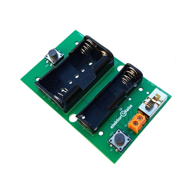
Elektor Labs Elektor Milliohmmeter Adapter
The Elektor Milliohmmeter Adapter uses the precision of a multimeter to measure very low resistance values. It is an adapter that converts a resistance into a voltage that can be measured with a standard multimeter. The Elektor Milliohmmeter Adapter can measure resistances below 1 mΩ using a 4-wire (Kelvin) method. It is useful for locating short circuits on printed circuit boards (PCB). The adapter features three measurement ranges – 1 mΩ, 10 mΩ, and 100 mΩ – selectable via a slide switch. It also includes onboard calibration resistors. The Elektor Milliohmmeter Adapter is powered by three 1.5 V AA batteries (not included). Specifications Measurement ranges 1 mΩ, 10 mΩ, 100 mΩ, 0.1% Power supply 3x 1.5 V AA batteries (not included) Dimensions 103 x 66 x 18 mm (compatible with Hammond 1593N-type enclosure, not included) Special feature On-board calibration resistors Downloads Documentation
€ 34,95
Members: € 31,46
-

Elektor Publishing The BeagleY-AI Handbook
A Practical Guide to AI, Python, and Hardware Projects Welcome to your BeagleY-AI journey! This compact, powerful, and affordable single-board computer is perfect for developers and hobbyists. With its dedicated 4 TOPS AI co-processor and a 1.4 GHz Quad-core Cortex-A53 CPU, the BeagleY-AI is equipped to handle both AI applications and real-time I/O tasks. Powered by the Texas Instruments AM67A processor, it offers DSPs, a 3D graphics unit, and video accelerators. Inside this handbook, you‘ll find over 50 hands-on projects that cover a wide range of topics—from basic circuits with LEDs and sensors to an AI-driven project. Each project is written in Python 3 and includes detailed explanations and full program listings to guide you. Whether you‘re a beginner or more advanced, you can follow these projects as they are or modify them to fit your own creative ideas. Here’s a glimpse of some exciting projects included in this handbook: Morse Code Exerciser with LED or BuzzerType a message and watch it come to life as an LED or buzzer translates your text into Morse code. Ultrasonic Distance MeasurementUse an ultrasonic sensor to measure distances and display the result in real time. Environmental Data Display & VisualizationCollect temperature, pressure, and humidity readings from the BME280 sensor, and display or plot them on a graphical interface. SPI – Voltmeter with ADCLearn how to measure voltage using an external ADC and display the results on your BeagleY-AI. GPS Coordinates DisplayTrack your location with a GPS module and view geographic coordinates on your screen. BeagleY-AI and Raspberry Pi 4 CommunicationDiscover how to make your BeagleY-AI and Raspberry Pi communicate over a serial link and exchange data. AI-Driven Object Detection with TensorFlow LiteSet up and run an object detection model using TensorFlow Lite on the BeagleY-AI platform, with complete hardware and software details provided.
€ 44,95
Members: € 40,46
-

Elektor Publishing Control Engineering with Fuzzy Logic
Practical Applications and Project with Arduino, ESP32, and RP2040 Immerse yourself in the fascinating world of control engineering with Arduino and ESP32! This book offers you a practical introduction to classic and modern control methods, including PID controllers, fuzzy logic, and sliding-mode controllers. In the first part, you will learn the basics of the popular Arduino controllers, such as the Arduino Uno and the ESP32, as well as the integration of sensors for temperature and pH measurement (NTC, PT100, PT1000, and pH sensor). You will learn how to use these sensors in various projects and how to visualize data on a Nextion TFT display. The course continues with an introduction to actuators such as MOSFET switches, H-bridges, and solid-state relays, which are used to control motors and actuators. You will learn to analyze and model controlled systems, including PT1 and PT2 control. The book focuses on the implementation of fuzzy and PID controllers for controlling temperature and DC motors. Both the Arduino Uno and the ESP32 are used. The sliding-mode controller is also introduced. In the second-to-last chapter, you will explore the basics of neural networks and learn how machine learning can be used on an Arduino. In the last chapter, there is a practical example of a fuzzy controller for feeding electricity into the household grid. This book is the perfect choice for engineers, students, and electronics engineers who want to expand their projects with innovative control techniques.
€ 44,95
Members: € 40,46
-

Elektor Bundles 555 Timer Projects (Bundle)
This bundle is all about designing projects based on the 555 timer IC. The book features over 45 fully tested and documented projects. Together with the kit, which contains more than 130 through-hole components, you can build all the projects described on a breadboard. The setup also makes it easy to modify and experiment with the projects. Over 45 Builds for the Legendary 555 Chip (and the 556, 558) Some of the projects in the book are: Alternately Flashing Two LEDs Changing LED Flashing Rate Touch Sensor On/Off Switch Switch On/Off Delay Light-Dependent Sound Dark/Light Switch Tone Burst Generator Long Duration Timer Chasing LEDs LED Roulette Game Traffic Lights Continuity Tester Electronic Lock Switch Contact Debouncing Toy Electronic Organ Multiple Sensor Alarm System Metronome Voltage Multipliers Electronic Dice 7-Segment Display Counter Motor Control 7-Segment Display Dice Electronic Siren Various Other Projects Kit Contents Resistors 1x 15 kΩ 1x 68 kΩ 2x 47 kΩ 1x 82 kΩ 2x 820 Ω 1x 8.2 kΩ 3x 10 kΩ 1x 1.8 kΩ 1x 6.8 kΩ 14x 2.2 kΩ 10x 680 Ω 1x 27 kΩ 1x 5.6 kΩ 1x 560 kΩ 1x 4.7 kΩ 1x 3.3 kΩ 3x 33 kΩ 1x 36 kΩ 2x 100 kΩ 5x 1 kΩ 1x 3.9 kΩ 2x 56 kΩ 2x 12 kΩ 1x 10 kΩ potentiometer 1x 1 MΩ potentiometer 2x 50 kΩ potentiometer 3x 20 kΩ potentiometer 1x 10 kΩ potentiometer 1x 10 kΩ potentiometer 1x 50 kΩ potentiometer 1x 100 kΩ potentiometer 1x 50 kΩ potentiometer Capacitors 1x 0.33 μF 1x 1 μF 1x 10 nF 1x 22 nF 1x 47 nF 1x 100 nF 1x 10 μF electrolytic 1x 33 μF electrolytic 2x 100 μF electrolytic LEDs 10x 5 mm red LED 10x 3 mm red LED 3x 3 mm yellow LED 3x 3 mm green LED 1x Common-cathode 7-segment LED Semiconductors 3x 555 timer 1x CD4017 counter 1x CD4026 counter 1x CD4011 NAND gate 4x 1N4148 diode 1x IRFZ46N MOSFET 1x Thermistor 1x Light dependent resistor (LDR) Miscellaneous 1x Passive buzzer 1x Active buzzer 1x SG90 servo 1x 8 Ω mini loudspeaker 1x 9 V DC brushed motor 1x 5 V relay 1x 9 V battery clip 7x Pushbutton switches 1x Breadboard 1x Breadboard jumper wires
€ 69,95€ 54,95Best Price


