The Elektor MultiCalculator Kit is an Arduino-based multifunction calculator that goes beyond basic calculations. It offers 22 functions including light and temperature measurement, differential temperature analysis, and NEC IR remote control decoding. The Elektor MultiCalculator is a handy tool for use in your projects or for educational purposes.
The kit features a Pro Mini module as the computing unit. The PCB is easy to assemble using through-hole components. The enclosure consists of 11 acrylic panels and mounting materials for easy assembly. Additionally, the device is equipped with a 16x2 alphanumeric LCD, 20 buttons, and temperature sensors.
The Elektor MultiCalculator is programmable with the Arduino IDE through a 6-way PCB header. The available software is bilingual (English and Dutch). The calculator can be programmed with a programming adapter, and it is powered through USB-C.
Modes of Operation
Calculator
4-Ring Resistor Code
5-Ring Resistor Code
Decimal to Hexadecimal and Character (ASCII) conversion
Hexadecimal to Decimal and Character (ASCII) conversion
Decimal to Binary and Character (ASCII) conversion
Binary to Decimal and Hexadecimal conversion
Hz, nF, capacitive reactance (XC) calculation
Hz, µH, inductive reactance (XL) calculation
Resistance calculation of two resistors connected in parallel
Resistance calculation of two resistors connected in series
Calculation of unknown parallel resistor
Temperature measurement
Differential temperature measurement T1&T2 and Delta (δ)
Light measurement
Stopwatch with lap time function
Item counter
NEC IR remote control decoding
AWG conversion (American Wire Gauge)
Rolling Dice
Personalize startup message
Temperature calibration
Specifications
Menu languages: English, Dutch
Dimensions: 92 x 138 x 40 mm
Build time: approx. 5 hours
Included
PCB and though-hole components
Precut acrylic sheets with all mechanical parts
Pro Mini microcontroller module (ATmega328/5 V/16 MHz)
Programming adapter
Waterproof temperature sensors
USB-C cable
Downloads
Software
Raspberry Pi-based Eye Catcher
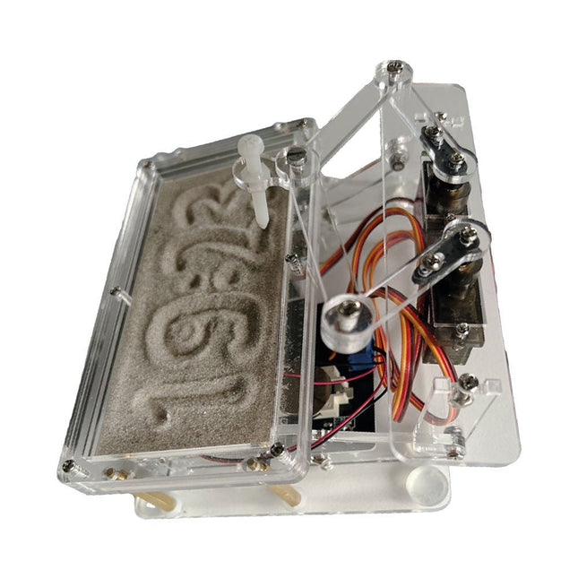
A standard sand clock just shows how time passes. In contrast, this Raspberry Pi Pico-controlled sand clock shows the exact time by “engraving” the four digits for hour and minute into the layer of sand. After an adjustable time the sand is flattened out by two vibration motors and everything begins all over again.
At the heart of the sand clock are two servo motors driving a writing pen through a pantograph mechanism. A third servo motor lifts the pen up and down. The sand container is equipped with two vibration motors to flatten the sand. The electronic part of the sand clock consists of a Raspberry Pi Pico and an RTC/driver board with a real-time clock, plus driver circuits for the servo motors.
A detailed construction manual is available for downloading.
Features
Dimensions: 135 x 110 x 80 mm
Build time: approx. 1.5 to 2 hours
Included
3x Precut acrylic sheets with all mechanical parts
3x Mini servo motors
2x Vibration motors
1x Raspberry Pi Pico
1x RTC/driver board with assembled parts
Nuts, bolts, spacers, and wires for the assembly
Fine-grained white sand
Arduino-compatible, ESP32-controlled, 2-wheeled Balancing Robot
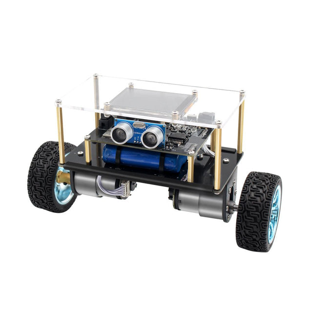
The Elektor Mini-Wheelie is an experimental autonomous self-balancing robot platform. Based on an ESP32-S3 microcontroller, the self-balancing robot is fully programmable using the Arduino environment and open-source libraries. Its wireless capabilities allow it to be controlled remotely over Wi-Fi, Bluetooth or ESP-NOW or to communicate with a user or even another robot.
An ultrasonic transducer is available for detecting obstacles. Its color display can be used for displaying cute facial expressions or, for the more down-to-earth users, cryptic debug messages.
The robot comes as a neat kit of parts that you must assemble yourself. Everything is included, even a screwdriver.
Note: The Mini-Wheelie is an educational development platform intended for learning, experimentation, and robotics development. It is not classified as a toy for children, and its features, documentation, and intended audience reflect this purpose. The product is aimed at students, educators, and developers who wish to explore robotics, programming, and hardware integration in an educational setting.
Specifications
ESP32-S3 microcontroller with Wi-Fi and Bluetooth
MPU6050 6-axis Inertial Measurement Unit (IMU)
Two independently controlled 12 V electric motors with tachometer
Ultrasonic transducer
2.9" TFT color display (320 x 240)
MicroSD card slot
Battery power monitor
3S rechargeable Li-Po battery (11.1 V/2200 mAh)
Battery charger included
Arduino-based open-source software
Dimensions (W x L x H): 23 x 8 x 13 cm
Included
1x ESP32-S3 Mainboard + MPU6050 module
1x LCD board (2.9 inch)
1x Ultrasonic sensor
1x Battery pack (2200 mAh)
1x Battery charger
1x Motor tyre kit
1x Case board
1x Acrylic board
1x Screwdriver
1x Protective strip
1x Flex cable B (8 cm)
1x Flex cable A (12 cm)
1x Flex cable C
4x Copper column A (25 mm)
4x Copper column B (55 mm)
4x Copper column C (5 mm)
2x Plastic nylon column
8x Screws A (10 mm)
24x Screws B (M3x5)
8x Nuts
24x Metal washers
2x Zip tie
1x MicroSD card (32 GB)
Downloads
Documentation
Build Your Own Vintage Radio Broadcaster
The Elektor AM Transmitter Kit allows streaming audio to vintage AM radio receivers. Based on a Raspberry Pi Pico microcontroller module, the AM Transmitter can transmit on 32 frequencies in the AM band, from 500 kHz up to 1.6 MHz in 32 steps of approx. 35 kHz.
The frequency is selected with a potentiometer and shown on a 0.96" OLED display. A pushbutton allows toggles the transmitting mode between On and Off. The range of the transmitter depends on the antenna. The onboard antenna provides a range of a few centimeters, requiring the AM Transmitter to be placed close to or inside the radio. An external loop antenna (not included) can be connected to increase the range.
The Elektor AM Transmitter Kit comes as a kit of parts that you must solder to the board yourself.
Features
The board is compatible with a Hammond 1593N enclosure (not included).A 5 VDC power supply with micro-USB connector (e.g., an old phone charger) is needed to power the kit (not included). Current consumption is 100 mA.
The Arduino software (requiring Earle Philhower’s RP2040 Boards Package) for the Elektor AM Transmitter Kit plus more information is available at the Elektor Labs page of this project.
Component List
Resistors
R1, R4 = 100 Ω
R2, R3, R8 = 10 kΩ
R5, R6, R9, R10, R11 = 1 kΩ
R7 = optional (not included)
P1 = potentiometer 100 kΩ, linear
Capacitors
C1 = 22 µF 16V
C2, C4 = 10 nF
C3 = 150 pF
Miscellaneous
K1 = 4×1 pin socket
K2, K3 = 3.5 mm socket
Raspberry Pi Pico
pushbutton, angle mount
0.96" monochrome I²C OLED display
PCB 150292-1
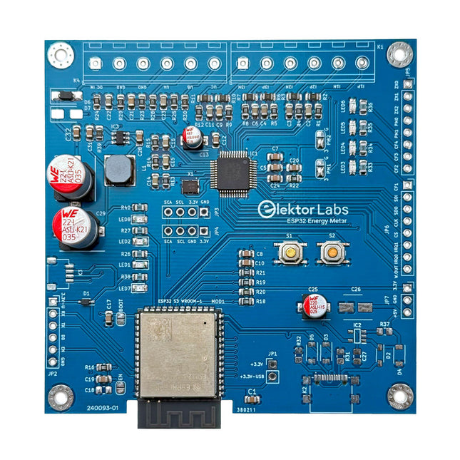
The Elektor ESP32 Energy Meter is a device designed for real-time energy monitoring and smart home integration. Powered by the ESP32-S3 microcontroller, it offers robust performance with modular and scalable features.
The device uses a 220 V-to-12 V step-down transformer for voltage sampling, ensuring galvanic isolation and safety. Its compact PCB layout includes screw-type terminal blocks for secure connections, a Qwiic connector for additional sensors, and a programming header for direct ESP32-S3 configuration. The energy meter is compatible with single-phase and three-phase systems, making it adaptable for various applications.
The energy meter is simple to set up and integrates with Home Assistant, offering real-time monitoring, historical analytics, and automation capabilities. It provides accurate measurements of voltage, current, and power, making it a valuable tool for energy management in homes and businesses.
Features
Comprehensive Energy Monitoring: Get detailed insights into your energy usage for smarter management and cost savings.
Customizable Software: Tailor functionality to your needs by programming and integrating custom sensors.
Smart Home Ready: Compatible with ESPHome, Home Assistant, and MQTT for full Smart Home integration.
Safe & Flexible Design: Operates with a 220 V-to-12 V step-down transformer and features a pre-assembled SMD board.
Quick Start: Includes one Current Transformer (CT) sensor and access to free setup resources.
Specifications
Microcontroller
ESP32-S3-WROOM-1-N8R2
Energy Metering IC
ATM90E32AS
Status Indicators
4x LEDs for power consumption indication2x Programmable LEDs for custom status notifications
User Input
2x Push buttons for user control
Display Output
I²C OLED display for real-time power consumption visualization
Input Voltage
110/220 V AC (via step-down transformer)
Input Power
12 V (via step-down transformer or DC input)
Clamp Current Sensor
YHDC SCT013-000 (100 A/50 mA) included
Smart Home Integration
ESPHome, Home Assistant, and MQTT for seamless connectivity
Connectivity
Header for programming, Qwiic for sensor expansion
Applications
Supports single-phase and three-phase energy monitoring systems
Dimensions
79.5 x 79.5 mm
Included
1x Partly assembled board (SMDs are pre-mounted)
2x Screw terminal block connectors (not mounted)
1x YHDC SCT013-000 current transformer
Required
Power transformer not included
Downloads
Datasheet (ESP32-S3-WROOM-1)
Datasheet (ATM90E32AS)
Datasheet (SCT013-000)
Frequently Asked Questions (FAQ)
From Prototype to Finished Product
What started as an innovative project to create a reliable and user-friendly energy meter using the ESP32-S3 microcontroller has evolved into a robust product. Initially developed as an open-source project, the ESP32 Energy Meter aimed to provide precise energy monitoring, smart home integration and more. Through meticulous hardware and firmware development, the energy meter now stands as a compact, versatile solution for energy management.
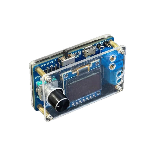
The DIY Mini Digital Oscilloscope Kit (with shell) is an easy-to-build kit for a tiny digital oscilloscope. Besides the power switch, it has only one other control, a rotary encoder with a built-in pushbutton. The kit's microcontroller comes preprogrammed. The 0.96" OLED display has a resolution of 128 x 64 pixels. The oscilloscope features one channel that can measure signals up to 100 kHz. The maximum input voltage is 30 V, the minimum voltage is 0 V.
The kit consists of through-hole components (THT) are surface-mount devices (SMD). Therefore, assembling the kit means soldering SMD parts, which requires some soldering experience.
Specifications
Vertical range: 0 to 30 V
Horizontal range: 100 µs to 500 ms
Trigger type: auto, normal and single
Trigger edge: rising and falling
Trigger level: 0 to 30 V
Run/Stop mode
Automatic frequency measurement
Power: 5 V micro-USB
10 Hz, 5 V sinewave output
9 kHz, 0 to 4.8 V square wave output
Display: 0.96-inch OLED screen
Dimensions: 57 x 38 x 26 mm
Downloads
Documentation
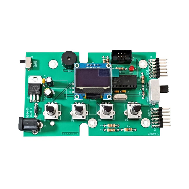
The Elektor Super Servo Tester can control servos and measure servo signals. It can test up to four servo channels at the same time.
The Super Servo Tester comes as a kit. All the parts required to assemble the Super Servo Tester are included in the kit. Assembling the kit requires basic soldering skills. The microcontroller is already programmed.
The Super Servo Tester features two operating modes: Control/Manual and Measure/Inputs.
In Control/Manual mode the Super Servo Tester generates control signals on its outputs for up to four servos or for the flight controller or ESC. The signals are controlled by the four potentiometers.
In Measure/Inputs the Super Servo Tester measures the servo signals connected to its inputs. These signals may come from for instance an ESC, a flight controller, or the receiver or another device. The signals are also routed to the outputs to control the servos or the flight controller or ESC. The results are shown on the display.
Specifications
Operating modes
Control/Manual & Measure/Inputs
Channels
3
Servo signal inputs
4
Servo signal outputs
4
Alarm
Buzzer & LED
Display
0.96' OLED (128 x 32 pixels)
Input voltage on K5
7-12 VDC
Input voltage on K1
5-7.5 VDC
Input current
30 mA (9 VDC on K5, nothing connected to K1 and K2)
Dimensions
113 x 66 x 25 mm
Weight
60 g
Included
Resistors (0.25 W)
R1, R3
1 kΩ, 5%
R2, R4, R5, R6, R7, R9, R10
10 kΩ, 5%
R8
22 Ω, 5%
P1, P2, P3, P4
10 kΩ, lin/B, vertical potentiometer
Capacitors
C1
100 µF 16 V
C2
10 µF 25 V
C3, C4, C7
100 nF
C5, C6
22 pF
Semiconductors
D1
1N5817
D2
LM385Z-2.5
D3
BZX79-C5V1
IC1
7805
IC2
ATmega328P-PU, programmed
LED1
LED, 3 mm, red
T1
2N7000
Miscellaneous
BUZ1
Piezo buzzer with oscillator
K1, K2
2-row, 12-way pinheader, 90°
K5
Barrel jack
K4
1-row, 4-way pin socket
K3
2-row, 6-way boxed pinheader
S1
Slide switch DPDT
S2
Slide switch SPDT
X1
Crystal, 16 MHz
28-way DIP socket for IC2
Elektor PCB
OLED display, 0.96', 128 x 32 pixels, 4-pin I²C interface
Links
Elektor Magazine
Elektor Labs
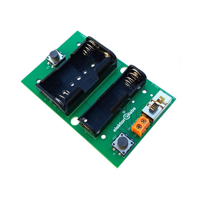
The Elektor Milliohmmeter Adapter uses the precision of a multimeter to measure very low resistance values. It is an adapter that converts a resistance into a voltage that can be measured with a standard multimeter.
The Elektor Milliohmmeter Adapter can measure resistances below 1 mΩ using a 4-wire (Kelvin) method. It is useful for locating short circuits on printed circuit boards (PCB).
The adapter features three measurement ranges – 1 mΩ, 10 mΩ, and 100 mΩ – selectable via a slide switch. It also includes onboard calibration resistors. The Elektor Milliohmmeter Adapter is powered by three 1.5 V AA batteries (not included).
Specifications
Measurement ranges
1 mΩ, 10 mΩ, 100 mΩ, 0.1%
Power supply
3x 1.5 V AA batteries (not included)
Dimensions
103 x 66 x 18 mm (compatible with Hammond 1593N-type enclosure, not included)
Special feature
On-board calibration resistors
Downloads
Documentation
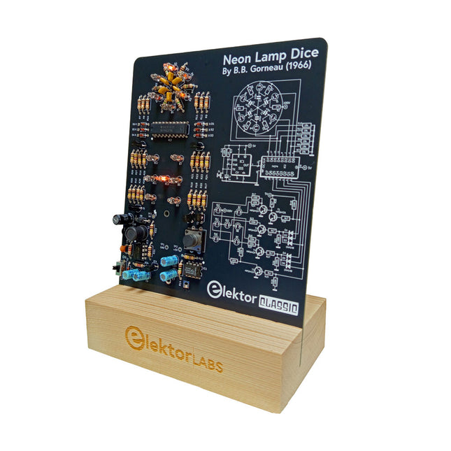
A Retro Roll with a Neon Soul
LED-based dice are common, but their light is cold. Not so for this electronic neon dice, which displays its value with the warm glow of neon lamps. It is perfect for playing games on cold, dark winter evenings. The pips of the dice are neon lamps and the random number generator has six neon lamps to show that it is working.
Even though the dice has an on-board 100-V power supply, it is completely safe. As with all Elektor Classic products, the dice too has its circuit diagram printed on the front while an explanation of how the circuit works can be found on the rear side.
The Neon Lamp Dice comes as a kit of easy-to-solder through-hole parts. The power supply is a 9-V battery (not included).
Features
Warm Vintage Glow
Elektor Heritage Circuit Symbols
Tried & Tested by Elektor Labs
Educational & Geeky Project
Through-Hole Parts Only
Included
Printed Circuit Board
All Components
Wooden Stand
Required
9 V battery
Component List
Resistors (THT, 150 V, 0.25 W)
R1, R2, R3, R4, R5, R6, R14 = 1 MΩ
R7, R8, R9, R10, R11, R12 = 18 kΩ
R13, R15, R16, R17, R18, R21, R23, R24, R25, R26, R28, R30, R33 = 100 kΩ
R32, R34 = 1.2 kΩ
R19, R20, R22, R27, R29 = 4.7 kΩ
R31 = 1 Ω
Capacitors
C1, C2, C3, C4, C5, C6 = 470 nF, 50 V, 5 mm pitch
C7, C9, C11, C12 = 1 µF, 16 V, 2 mm pitch
C8 = 470 pF, 50 V, 5 mm pitch
C10 = 1 µF, 250 V, 2.5 mm pitch
Inductors
L1 = 470 µH
Semiconductors
D1, D2, D3, D4, D5, D6, D7 = 1N4148
D8 = STPS1150
IC1 = NE555
IC2 = 74HC374
IC3 = MC34063
IC4 = 78L05
T1, T2, T3, T4, T5 = MPSA42
T6 = STQ2LN60K3-AP
Miscellaneous
K1 = PP3 9 V battery holder
NE1, NE2, NE3, NE4, NE5, NE6, NE7, NE8, NE9, NE10, NE11, NE12, NE13 = neon light
S2 = Miniature slide switch
S1 = Pushbutton (12 x 12 mm)
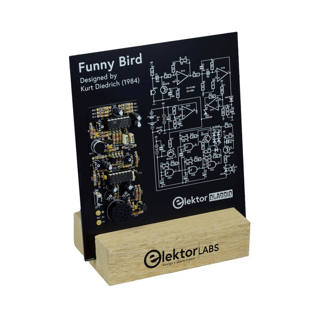
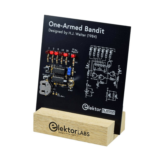
Pull Down Lever For Highest Score!
This Elektor Circuit Classic from 1984 shows a playful application of CMOS 400x series logic ICs in combination with LEDs, a highly popular combination at the time. The project imitates a spinning-digit type slot machine.
The Game
To play the game, first agree on the number of rounds. Player 1 actuates the switch lever as long as desired and releases it. The LEDs then show the score which is the sum of the 50-20-10-5 digits lit up. If the Play Again! LED lights, Player 1 has another, “free” round. If not, it’s Player 2’s turn. The players keep tab of their scores, and the highest score wins.
Features
LEDs Indicate Score
Multi-Player and Play Again!
Elektor Heritage Circuit Symbols
Tried & Tested by Elektor Labs
Educational & Geeky Project
Through-Hole Parts Only
Included
Printed Circuit Board
All Components
Wooden Stand
Bill of Materials
Resistors (5%, 250 mW)
R1,R2,R3,R4 = 100kΩ
R5,R6,R7,R8,R9,R10 = 1kΩ
Capacitors
C1 = 4.7nF, 10%, 50V, 5mm
C2 = 4.7μF, 10%, 63V, axial
C3,C4 = 100nF, 10 %, 50V, ceramic X7R, 5mm
Semiconductors
LED1-LED6 = red, 5mm (T1 3/4)
IC1 = 74HC4024
IC2 = 74HC132
Miscellaneous
S1 = switch, toggle, 21mm lever, SPDT, momentary
S2 = switch, tactile, 24V, 50mA, 6x6mm
S3 = switch, slide, SPDT
IC1,IC2 = IC socket, DIP14
BT1 = PCB-mount CR2032 battery retainer clip
Desktop Stand
PCB 230098-1
Not included: BT1 = CR2032 coin cell battery
Multilingual DIY Kit (incl. 27 RGB LEDs + Raspberry Pi Pico)
Bring some engineering magic to your festive season with the Wordy LED Christmas Tree, a unique DIY electronics kit designed by Elektor. This beautifully engineered 3D Christmas tree combines eleven PCBs, a Raspberry Pi Pico, and 27 addressable RGB LEDs to illuminate Christmas greetings in seven languages: Danish, Dutch, English, French, German, Italian, and Spanish.
Unlike ordinary LED trees, each word inside the tree has its own light chamber, creating a refined, softly glowing display without sound or flicker. The LEDs are fully WS2812-compatible and driven via the popular Adafruit NeoPixel library, making custom animations and color effects easy to create.
Perfect for makers, tinkerers, and festive electronics fans, this kit offers both an enjoyable build and a striking, conversation-worthy decoration. The Wordy Christmas Tree is your perfect holiday maker project!
Features
Multilingual greetings (7 languages) milled into the front panel
3D construction from 11 interlocking PCBs
Powered by Raspberry Pi Pico
27 individually addressable RGB LEDs (pre-mounted)
Smooth fade-in and fade-out animations
Fully programmable using the Arduino IDE
A 5-V power supply (with micro-USB connector) capable of ≥1 A is recommended for maximum brightness (not included)
Dimensions (H x W x D): 130 x 115 x 75 mm
Included
All required PCBs with LEDs and other SMD parts mounted
Raspberry Pi Pico (to be soldered & programmed by the user)
3-way pin header (to be soldered by the user)
3-way pin socket (to be soldered by the user)
4x Self-adhesive dome bumpers
Project Page
Elektor Labs
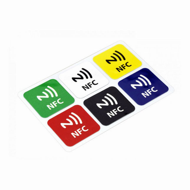
Features NFC chip material: PET + Etching antenna Chip: NTAG216 (compatible with all NFC phones) Frequency: 13.56 MHz (High Frequency) Reading time: 1 - 2 ms Storage capacity: 888 bytes Read and write times: > 100,000 times Reading distance: 0 - 5 mm Data retention: > 10 years NFC chip size: Diameter 30 mm Non-contact, no friction, the failure rate is small, low maintenance costs Read rate, verification speed, which can effectively save time and improve efficiency Waterproof, dustproof, anti-vibration No power comes with an antenna, embedded encryption control logic, and communication logic circuit Included 1x NFC Stickers (6-color kit)
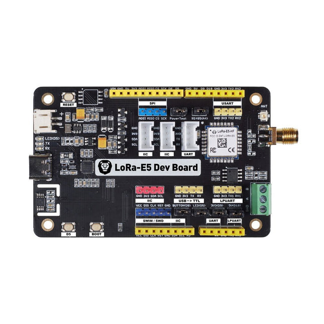
LoRa-E5 Development Kit is an easy-to-use compact development toolset for you to unlock the powerful performance of the LoRa-E5 STM32WLE5JC. It consists of a LoRa-E5 Dev Board, an antenna (EU868), a USB type C cable, and a 2-AA 3 V Battery Holder.
LoRa-E5 Dev Board embedded with LoRa-E5 STM32WLE5JC Module, which is the world-first combo of LoRa RF and MCU chip into one single tiny chip and is FCC and CE certified. It is powered by ARM Cortex-M4 core and Semtech SX126X LoRa chip, supports both LoRaWAN and LoRa protocol on the worldwide frequency and (G)FSK, BPSK, (G)MSK, and LoRa modulations.
The LoRa-E5 development board features a very long transmission range, extremely low power consumption and user-friendly interfaces.
LoRa-E5 Dev Board has a long-distance transmission range of LoRa-E5 up to 10 km in an open area. The sleep current of LoRa-E5 modules on board is as low as 2.1 uA (WOR mode). It is designed with industrial standards with a wide working temperature at -40℃ ~ 85℃, high sensitivity between -116.5 dBm ~ -136 dBm, and power output up to +20.8 dBm at 3.3 V.
LoRa-E5 Dev Board also has rich interfaces. Developed to unlock the full functionality of the LoRa-E5 module, LoRa-E5 Dev Board has led out full 28 pins of LoRa-E5 and provides with rich interfaces including Grove connectors, RS-485 terminal, male/female pin headers for you to connect sensors and modules with different connectors and data protocols, saving your time on wire soldering. You could also easily power the board by connecting the battery holder with 2-AA batteries, enabling temporary use when lacking an external power source. It is a user-friendly board for easy testing and rapid prototyping.
Specifications
Size
LoRa-E5 Dev Board: 85.6 x 54 mm
Voltage (supply)
3-5 V (Battery) / 5 V (USB-C)
Voltage (output)
EN 3V3 / 5 V
Power (output)
Up to +20.8 dBm at 3.3 V
Frequency
EU868
Protocol
LoRaWAN
Sensitivity
-116.5 dBm ~ -136 dBm
Interfaces
USB Type C / JST2.0 / 3x Grove (2x I²C/1x UART) / RS485 / SMA-K / IPEX
Modulation
LoRa, (G)FSK, (G)MSK, BPSK
Working temperature
-40℃ ~ 85℃
Current
LoRa-E5 module sleep current as low as 2.1 uA (WOR mode)
Included
1x LoRa-E5 Dev Board
1x Antenna (EU868)
1x USB Type C Cable (20 cm)
1x 2-AA 3 V Battery Holder
This bundle contains the popular Elektor Sand Clock for Raspberry Pi Pico and the new Elektor Laser Head Upgrade, offering even more options for displaying the time. Not only can you "engrave" the current time in sand, you can now alternatively write it on a glow-in-the-dark foil or create green drawings.
Contents of the bundle
Elektor Sand Clock for Raspberry Pi Pico (normal price: €50)
Elektor Laser Head Upgrade for Sand Clock (normal price: €35)
Elektor Sand Clock for Raspberry Pi (Raspberry Pi-based Eye Catcher)
A standard sand clock just shows how time passes. In contrast, this Raspberry Pi Pico-controlled sand clock shows the exact time by "engraving" the four digits for hour and minute into the layer of sand. After an adjustable time the sand is flattened out by two vibration motors and everything begins all over again.
At the heart of the sand clock are two servo motors driving a writing pen through a pantograph mechanism. A third servo motor lifts the pen up and down. The sand container is equipped with two vibration motors to flatten the sand. The electronic part of the sand clock consists of a Raspberry Pi Pico and an RTC/driver board with a real-time clock, plus driver circuits for the servo motors.
A detailed construction manual is available for downloading.
Features
Dimensions: 135 x 110 x 80 mm
Build time: approx. 1.5 to 2 hours
Included
3x Precut acrylic sheets with all mechanical parts
3x Mini servo motors
2x Vibration motors
1x Raspberry Pi Pico
1x RTC/driver board with assembled parts
Nuts, bolts, spacers, and wires for the assembly
Fine-grained white sand
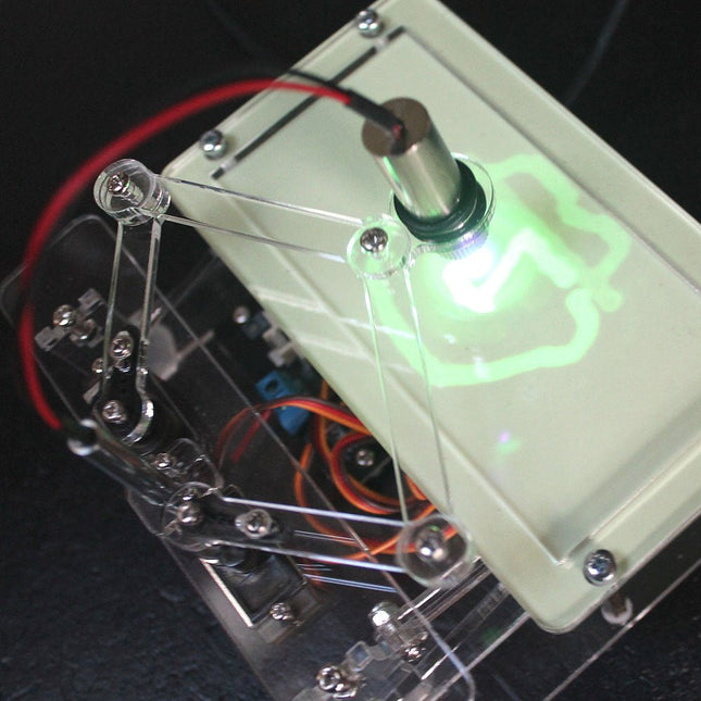
Elektor Laser Head Upgrade for Sand Clock
The new Elektor Laser Head transforms the Sand Clock into a clock that writes the time on glow-in-the-dark film instead of sand. In addition to displaying the time, it can also be used to create ephemeral drawings. The 5 mW laser pointer, with a wavelength of 405 nm, produces bright green drawings on the glow-in-the-dark film. For best results, use the kit in a dimly lit room. Warning: Never look directly into the laser beam!
The kit includes all the necessary components, but soldering three wires is required.
Note: This kit is also compatible with the original Arduino-based Sand Clock from 2017. For more details, see Elektor Magazine 1-2/2017 and Elektor Magazine 1-2/2018.
The Elektor Laser Head transforms the Elektor Sand Clock into a clock that writes the time on glow-in-the-dark film instead of sand. In addition to displaying the time, it can also be used to create ephemeral drawings. The 5 mW laser pointer, with a wavelength of 405 nm, produces bright green drawings on the glow-in-the-dark film. For best results, use the kit in a dimly lit room. Warning: Never look directly into the laser beam!
The kit includes all the necessary components, but soldering three wires is required.
Note: This kit is also compatible with the original Arduino-based Sand Clock from 2017. For more details, see Elektor Magazine 1-2/2017 and Elektor Magazine 1-2/2018.
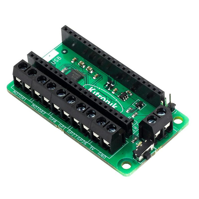
This board allows the Raspberry Pi Pico (connected via pin header) to drive two motors simultaneously with full forward, reverse & stop control, making it ideal for Pico controlled buggy projects. Alternatively, the board can be used to power a stepper motor. The board features the DRV8833 motor driver IC, which has built-in short circuit, over current and thermal protection.
The board has 4 external connections to GPIO pins and a 3 V and GND supply from the Pico. This allows for additional IO options for your buggy builds that can be read or controlled by the Pico. In addition there is an on/off switch and power status LED, allowing you to see at a glance if the board is powered up and save your batteries when your project is not in use.
To use the motor driver board, the Pico should have a soldered pin header and be inserted firmly into the connector. The board produces a regulated supply that is fed into the 40-way connector to power the Pico, removing the need to power the Pico directly. The motor driver board is powered via either screw terminals or a servo style connector.
Kitronik has developed a micro-python module and sample code to support the use of the Motor Driver board with the Pico. This code is available in the GitHub repo.
Features
A compact yet feature-packed board designed to sit at the heart of your Raspberry Pi Pico robot buggy projects.
The board can drive 2 motors simultaneously with full forward, reverse, and stop control.
It features the DRV8833 motor driver IC, which has built-in short circuit, over current and thermal protection.
Additionally, the board features an on/off switch and power status LED.
Power the board via a terminal block style connector.
The 3V and GND pins are also broken out, allowing external devices to be powered.
Code it with MicroPython via an editor such as the Thonny editor.
Dimensions: 63 mm (L) x 35 mm (W) x 11.6 mm (H)
Download
Datasheet
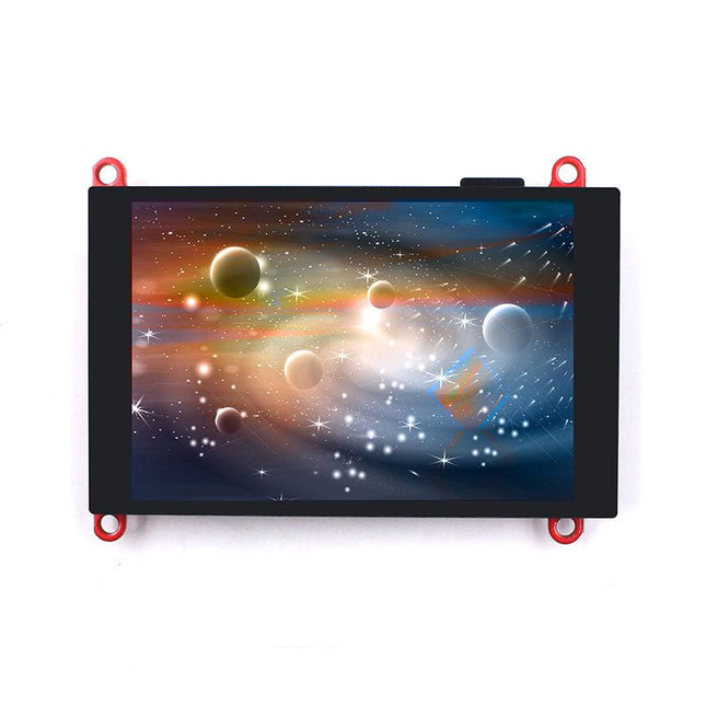
The ESP32-S3 Parallel TFT not only offers more SRAM and ROM (compared to the S2 version), but with Bluetooth 5.0 it is also suitable for applications such as local monitoring and controlling.
The built-in LCD driver ILI9488 uses 16-bit parallel lines to communicate with ESP32-S3, the main clock can be up to 20 MHz, which makes the display smooth enough for video displays. With this display, you can create more IoT display projects.
Features
Controller: ESP32-S3-WROOM-1, PCB Antenna, 16 MB Flash, 2 MB PSRAM, ESP32-S3-WROOM-1-N16R2
Wireless: Wifi & Bluetooth 5.0
LCD: 3.5-inch TFT LCD
Resolution: 480x320
Color: RGB
LCD Interface: 16-bit parallel
LCD Driver: ILI9488
Touch Panel: Capacitive
Touch Panel Driver: FT6236
USB: Dual USB Type-C (one for USB-to-UART and one for native USB)
UART to UART Chip: CP2104
Power Supply: USB Type-C 5.0 V (4.0 V~5.25 V)
Button: Flash button and reset button
Mabee Interface: 1x I²C, 1x GPIO
Backlight Controller: Yes
MicroSD: Yes
Arduino support: Yes
Type-C Power Delivery: Not supported
Operation temperature: -40℃ to +85℃
Dimension: 66 x 84.3 x 12 mm
Weight: 52 g
Downloads
ESP32-S3 Datasheet
GitHub
Wiki
LVGL Demo Code
Features
Build in USB to Serial interface
Build-in PCB antenna
Powered by Pineseed BL602 SoC using Pinenut model: 12S stamp
2 MB Flash
USB-C connection
Suitable to breadboard BIY project
On board three color LEDs output
Dimensions: 25.4 x 44.0 mm
Note: USB cable is not included.
The FRDM-MCXN947 is a compact and versatile development board designed for rapid prototyping with MCX N94 and N54 microcontrollers. It features industry-standard headers for easy access to the MCU's I/Os, integrated open-standard serial interfaces, external flash memory, and an onboard MCU-Link debugger.
Specifications
Microcontroller
MCX-N947 Dual Arm Cortex-M33 cores @ 150 MHz each with optimized performance efficiency, up to 2 MB dual-bank flash with optional full ECC RAM, External flash
Accelerators: Neural Processing Unit, PowerQuad, Smart DMA, etc.
Memory Expansion
*DNP Micro SD card socket
Connectivity
Ethernet Phy and connector
HS USB-C connectors
SPI/I²C/UART connector (PMOD/mikroBUS, DNP)
WiFi connector (PMOD/mikroBUS, DNP)
CAN-FD transceiver
Debug
On-board MCU-Link debugger with CMSIS-DAP
JTAG/SWD connector
Sensor
P3T1755 I³C/I²C Temp Sensor, Touch Pad
Expansion Options
Arduino Header (with FRDM expansion rows)
FRDM Header
FlexIO/LCD Header
SmartDMA/Camera Header
Pmod *DNP
mikroBUS
User Interface
RGB user LED, plus Reset, ISP, Wakeup buttons
Included
1x FRDM-MCXN947 Development Board
1x USB-C Cable
1x Quick Start Guide
Downloads
Datasheet
Block diagram
This Crowtail series 4G module is a high-performance LTE Cat1 wireless module. It uses the SIM A7670E communication module from Simcom and communicates through a UART interface, which enables 4G data transmission and voice communication. The module supports multiple LTE bands, including B1/B3/B5/B7/B8/B20, as well as WCDMA and GSM networks. In addition, it supports various protocols such as TCP/IP, FTP, HTTP, and multiple satellite navigation systems such as GPS, GLONASS, and BDS.
The module comes with a charging interface and can be powered by a 3.7 V lithium battery or a 5 V USB-C interface. It also has a 3.5 mm headphone jack, and by connecting a headphone with a microphone, it can be used for making and receiving phone calls. Its compact size makes it easy to integrate into various IoT devices and meet various application requirements. Furthermore, its low power consumption and reliable performance are also the reasons why it is widely used in IoT, smart home, automotive, and industrial control fields.
Features
Integrate the A7670E communication module, enabling 4G data transmission and voice communication with low power consumption and high reliability
Supports multiple LTE bands, including B1/B3/B5/B7/B8/B20, as well as WCDMA and GSM networks
Supports various protocols such as TCP/IP, FTP, HTTP, and multiple satellite navigation systems such as GPS, GLONASS, and BDS
Comes with a charging interface and a headphone jack, which can be used for making and receiving phone calls by connecting a headphone with a microphone
Small but powerful, compact size makes it easy to integrate into various IoT devices.
Specifications
Main Chip: SIM A7670E
LTE-FDD: B1/B3/B5/B7/B8/B20
GSM: 900/1800 MHz
GSM/GPRS power class
EGSM900: 4 (33 dBm ±2 dB)
DCS1800: 1 (30 dBm ±2 dB)
EDGE power class:
EGSM900: E2 (27 dBm ±3 dB)
DCS1800 : E1 (26 dBm +3 dB/-4 dB)
LTE power class: 3 (23 dBm ±7 dB)
Supply Voltage: 4 V ~ 4.2 V
Power: 3.8 V
LTE(Mbps): 10 (DL)/5 (UL)
GPRS/EDGE(Kbps): 236.8 (DL)/236.8 (UL)
Protocol: TCP/IP/IPV4/IPV6/Multi-PDP/FTP/FTPS /HTTP/HTTPS/DNS
Communication interface: USB / UART
Firmware Upgrade: USB/FOTA
Support phonebook types: SM/FD/ON/AP/SDN
Interfaces: 1x Power button, 1x BAT, 1x UART, 1x USB-C, 1x SIM Card slot
Dimensions: 35 x 50 mm
Included
1x Crowtail-4G SIM-A7670E
1x 4G GSM NB-IoT Antenna
1x GPS ceramic antenna
Downloads
Wiki
A7670 AT Command Manual
A7670 Datasheet
Source Code
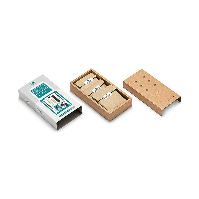
Learn the basics of electronics by assembling manually your Arduino Uno, become familiar with soldering by mounting every single component, and then unleash your creativity with the only kit that becomes a synth!
The Arduino Make-Your-Uno kit is really the best way to learn how to solder. And when you are done, the packaging allows you to build a synth and make your music.
A kit with all the components to build your very own Arduino Uno and audio synthesizer shield.
The Make-Your-Uno kit comes with a complete set of instructions in a dedicated content platform. This includes video material, a 3D interactive viewer for following detailed instructions, and how to program your board once it is finished.
This kit contains:
Arduino Make-Your-Uno
1x Make-Your-Uno PCB
1x USB C Serial adapter Board
7x Resistors 1k Ohm
2x Resistors 10k Ohm
2x Resistors 1M Ohm
1x Diode (1N4007)
1x 16 MHz Crystal
4x Yellow LEDs
1x Green LED
1x Push-Button
1x MOSFET
1x LDO (3.3 V)
1x LDO (5 V)
3x Ceramic capacitors (22pF)
3x Electrolytic capacitors (47uF)
7x Polyester capacitors (100nF)
1x Socket for ATMega 328p
2x I/O Connectors
1x Connector header 6 pins
1x Barrel jack connector
1x ATmega 328p Microcontroller
Arduino Audio Synth
1x Audio Synth PCB
1x Resistor 100k Ohm
1x Resistor 10 Ohm
1x Audio amplifier (LM386)
1x Ceramic capacitors (47nF)
1x Electrolytic capacitors (47uF)
1x Electrolytic capacitors (220uF)
1x Polyester capacitor (100nF)
4x connectors pin header
6x potentiometer 10k Ohm with plastic knobs
Spare parts
2x Electrolytic capacitors (47uF)
2x Polyester capacitor (100nF)
2x Ceramic capacitors (22pF)
1x Push-Button
1x Yellow LEDs
1x Green LED
Mechanical parts
5x Spacers 12 mm
11x Spacers 6 mm
5x screw nuts
2x screws 12 mm
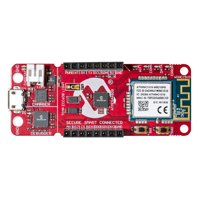
The AVR-IoT WA development board combines a powerful ATmega4808 AVR MCU, an ATECC608A CryptoAuthentication secure element IC and the fully certified ATWINC1510 Wi-Fi network controller – which provides the most simple and effective way to connect your embedded application to Amazon Web Services (AWS). The board also includes an on-board debugger, and requires no external hardware to program and debug the MCU.
Out of the box, the MCU comes preloaded with a firmware image that enables you to quickly connect and send data to the AWS platform using the on-board temperature and light sensors. Once you are ready to build your own custom design, you can easily generate code using the free software libraries in Atmel START or MPLAB Code Configurator (MCC).
The AVR-IoT WA board is supported by two award-winning Integrated Development Environments (IDEs) – Atmel Studio and Microchip MPLAB X IDE – giving you the freedom to innovate with your environment of choice.
Features
ATmega4808 microcontroller
Four user LED’s
Two mechanical buttons
mikroBUS header footprint
TEMT6000 Light sensor
MCP9808 Temperature sensor
ATECC608A CryptoAuthentication™ device
WINC1510 WiFi Module
On-board Debugger
Auto-ID for board identification in Atmel Studio and Microchip MPLAB X
One green board power and status LED
Programming and debugging
Virtual COM port (CDC)
Two DGI GPIO lines
USB and battery powered
Integrated Li-Ion/LiPo battery charger
The SparkFun RedBoard Qwiic is an Arduino-compatible board that combines features of different Arduinos with the Qwiic Connect System.
Features
ATmega328 microcontroller with Optiboot Bootloader
R3 Shield Compatible
CH340C Serial-USB Converter
3.3 V to 5 V Voltage Level Jumper
A4 / A5 Jumpers
AP2112 Voltage Regulator
ISP Header
Input voltage: 7 V - 15 V
1 Qwiic Connector
16 MHz Clock Speed
32 k Flash Memory
All SMD Construction
Improved Reset Button
Here you will find all kinds of parts, components and accessories you will need in various projects, starting from simple wires, sensors and displays to already pre-assembled modules and kits.