Bestsellers
-

Elektor Bundles Logic Analyzers in Practice (Bundle)
Book: Logic Analyzers in Practice Step-by-step instructions guide you through the analysis of modern protocols such as I²C, SPI, UART, RS-232, NeoPixel, WS28xx, HD44780 and 1-Wire. With the help of numerous experimental circuits based on the Raspberry Pi Pico, Arduino Uno and the Bus Pirate, you will learn the practical application of popular USB logic analyzers. All the experimental circuits presented in this book have been fully tested and are fully functional. The necessary program listings are included – no special programming or electronics knowledge is required for these circuits. The programming languages used are MicroPython and C along with the development environments Thonny and Arduino IDE. This book uses several models of flexible and widely available USB logic analyzers and shows the strengths and weaknesses of each price range. You will learn about the criteria that matter for your work and be able to find the right device for you. Whether Arduino, Raspberry Pi or Raspberry Pi Pico, the example circuits shown allow you to get started quickly with protocol analysis and can also serve as a basis for your own experiments. After reading this book, you will be familiar with all the important terms and contexts, conduct your own experiments, analyze protocols independently, culminating in a comprehensive knowledge set of digital signals and protocols. USB Logic Analyzer (8-ch, 24 MHz) This USB Logic Analyzer is an 8-channel logic analyzer with each input dual purposed for analog data recording. It is perfect for debugging and analyzing signals like I²C, UART, SPI, CAN and 1-Wire. It operates by sampling a digital input connected to a device under test (DUT) at a high sample rate. The connection to the PC is via USB. Specifications Channels 8 digital channels Maximum sampling rate 24 MHz Maximum input voltage 0 V ~ 5 V Operating temperature 0°C ~ 70°C Input impedance 1 MΩ || 10 pF Supported protocols I²C, SPI, UART, CAN, 1-Wire, etc. PC connection USB Dimensions 55 x 28 x 14 mm Downloads Software This bundle contains: Book 'Logic Analyzers in Practice' (normal price: €35) USB Logic Analyzer (8-ch, 24 MHz) (normal price: €20) USB Cable Jumper Wire Ribbon Cable
€ 54,95€ 44,95Best Price
-
Elektor Digital Raspberry Pi 5 Essentials (E-book)
Program, build, and master over 60 projects with Python The Raspberry Pi 5 is the latest single-board computer from the Raspberry Pi Foundation. It can be used in many applications, such as in audio and video media centers, as a desktop computer, in industrial controllers, robotics, and in many domestic and commercial applications. In addition to the well-established features found in other Raspberry Pi computers, the Raspberry Pi 5 offers Wi-Fi and Bluetooth (classic and BLE), which makes it a perfect match for IoT as well as in remote and Internet-based control and monitoring applications. It is now possible to develop many real-time projects such as audio digital signal processing, real-time digital filtering, real-time digital control and monitoring, and many other real-time operations using this tiny powerhouse. The book starts with an introduction to the Raspberry Pi 5 computer and covers the important topics of accessing the computer locally and remotely. Use of the console language commands as well as accessing and using the desktop GUI are described with working examples. The remaining parts of the book cover many Raspberry Pi 5-based hardware projects using components and devices such as LEDs and buzzers LCDs Ultrasonic sensors Temperature and atmospheric pressure sensors The Sense HAT Camera modules Example projects are given using Wi-Fi and Bluetooth modules to send and receive data from smartphones and PCs, and sending real-time temperature and atmospheric pressure data to the cloud. All projects given in the book have been fully tested for correct operation. Only basic programming and electronics experience are required to follow the projects. Brief descriptions, block diagrams, detailed circuit diagrams, and full Python program listings are given for all projects described.
€ 32,95
Members: € 29,66
-

FNIRSI FNIRSI HRM-10 Battery Internal Resistance & Voltage Tester
The FNIRSI HRM-10 is a portable, high-precision battery internal resistance and voltage tester. This device offers true four-wire measurement and is designed for both accuracy and ease of use. It automatically measures internal resistance and voltage values simultaneously, displaying the results on its HD color screen. Users have the option to manually adjust voltage and resistance ranges to suit their needs. The device also includes a sorting mode that automatically filters the good and bad batteries based on user-set thresholds. Additionally, it supports the storage of historical data and allows for exporting measurement records in table format. Features High Measurement Accuracy Tabular Data Export Auto-Evaluate Measurement Results 8 Threshold Settings HD Color Screen Folding Stand 1000 mAh Lithium Battery Specifications Voltage Resistance Measuring range 0-100 V (DC) 0-200 Ω Accuracy ±0.5% ±0.5% Gear Automatic, 1 V, 10 V, 100 V Automatic, 20 mΩ, 200 mΩ, 2 Ω, 20 Ω, 200 Ω Instrument test signal frequency 1 Khz (AC) Rechargeable USB-C (5 V/1 A) Built-in battery 1000 mAh lithium battery User calibration Yes Sorting mode Yes History record Yes Recorded data export Yes Working environment –10°C to +45°C, relative humidity <80% Storage environment –20°C to +80°C, relative humidity <80% Dimensions 158.7 x 80.5 x 28.4 mm Weight 225 g Included 1x FNIRSI HRM-10 Internal Resistance Tester 1x Clip Test Line 1x USB-C data cable 1x Manual Downloads Manual Firmware V0.3
€ 49,95
-

Elektor Digital Nucleo Boards Programming with the STM32CubeIDE (E-book)
Hands-on in more than 50 projects STM32 Nucleo family of processors are manufactured by STMicroelectronics. These are low-cost ARM microcontroller development boards. This book is about developing projects using the popular STM32CubeIDE software with the Nucleo-L476RG development board. In the early Chapters of the book the architecture of the Nucleo family is briefly described. The book covers many projects using most features of the Nucleo-L476RG development board where the full software listings for the STM32CubeIDE are given for each project together with extensive descriptions. The projects range from simple flashing LEDs to more complex projects using modules, devices, and libraries such as GPIO, ADC, DAC, I²C, SPI, LCD, DMA, analogue inputs, power management, X-CUBE-MEMS1 library, DEBUGGING, and others. In addition, several projects are given using the popular Nucleo Expansion Boards. These Expansion Boards plug on top of the Nucleo development boards and provide sensors, relays, accelerometers, gyroscopes, Wi-Fi, and many others. Using an expansion board together with the X-CUBE-MEMS1 library simplifies the task of project development considerably. All the projects in the book have been tested and are working. The following sub-headings are given for each project: Project Title, Description, Aim, Block Diagram, Circuit Diagram, and Program Listing for the STM32CubeIDE. In this book you will learn about STM32 microcontroller architecture; the Nucleo-L476RG development board in projects using the STM32CubeIDE integrated software development tool; external and internal interrupts and DMA; DEBUG, a program developed using the STM32CubeIDE; the MCU in Sleep, Stop, and in Standby modes; Nucleo Expansion Boards with the Nucleo development boards. What you need a PC with Internet connection and a USB port; STM32CubeIDE software (available at STMicroelectronics website free of charge) the project source files, available from the book’s webpage hosted by Elektor; Nucleo-L476RG development board; simple electronic devices such as LEDs, temperature sensor, I²C and SPI chips, and a few more; Nucleo Expansion Boards (optional).
€ 39,95
Members: € 35,96
-
Elektor Publishing PLC Programming with the Raspberry Pi and the OpenPLC Project
ModbusRTU and ModbusTCP examples with the Arduino Uno and ESP8266 Introduction to PLC programming with OpenPLC, the first fully open source Programmable Logic Controller on the Raspberry Pi, and Modbus examples with Arduino Uno and ESP8266 PLC programming is very common in industry and home automation. This book describes how the Raspberry Pi 4 can be used as a Programmable Logic Controller. Before taking you into the programming, the author starts with the software installation on the Raspberry Pi and the PLC editor on the PC, followed by a description of the hardware. You'll then find interesting examples in the different programming languages complying with the IEC 61131-3 standard. This manual also explains in detail how to use the PLC editor and how to load and execute the programs on the Raspberry Pi. All IEC languages are explained with examples, starting with LD (Ladder Diagram) over ST (Structured Control Language) to SFC (Special Function Chart). All examples can be downloaded from the author's website. Networking gets thorough attention too. The Arduino Uno and the ESP8266 are programmed as ModbusRTU or ModbusTCP modules to get access to external peripherals, reading sensors and switching electrical loads. I/O circuits complying with the 24 V industry standard may also be of interest for the reader. The book ends with an overview of commands for ST and LD. After reading the book, the reader will be able to create his own controllers with the Raspberry Pi.
€ 39,95
Members: € 35,96
-

The Elektor RF & Communications Collection (USB Stick)
This USB stick holds a selection of more than 350 articles on RF, Radio and Communication published in Elektor Magazine. The content consists of both background articles and projects with the following topics: Basic radio-related circuits as well as more complex circuits like filters, oscillators, and amplifiers. Design, construction, and theory of antennas for transmitting and receiving radio signals efficiently. Design and analysis of RF circuits including filters, mixers, PLLs, and frequency synthesizers. Tools and techniques for predicting radio wave propagation paths and measuring RF signal strength. Techniques for processing digital signals in RF systems, including modulation and demodulation methods. Projects on radio receivers, AM, FM, SSB, CW, DRM, DAB, DAB+, Software Defined Radio, and more. Projects on Wi-Fi, Bluetooth, LoRaWAN, and more. You can use the article search function to locate specific content in the full text. The results are always shown as preformatted PDF documents. You can use Adobe Reader to browse articles, and you can use Adobe Reader’s integrated search functions to find instances of individual words and expressions.
€ 49,95€ 39,95Best Price
-
Elektor Digital Raspberry Pi Full Stack (E-book)
A comprehensive course that will teach you how to build a modern IoT application This book will take you on a whirlwind tour of full-stack web application development using Raspberry Pi. You will learn how to build an application from the ground up. You will gain experience and know-how of technologies including: The Linux operating system and command line. The Python programming language. The Raspberry Pi General Purpose Input Output pins (GPIOs). The Nginx web server. Flask Python web application microframework. JQuery and CSS for creating user interfaces. Dealing with time zones. Creating charts with Plotly and Google Charts. Data logging with Google Sheet. Developing applets with IFTTT. Securing your application with SSL. Receiving SMS notifications to your phone using Twilio. This book will also teach you how to set up a remote wireless Arduino sensor node and collect data from it. Your Raspberry Pi web application will be able to process Arduino node data in the same way it processes data from its onboard sensor. Raspberry Pi Full Stack will teach you many skills essential to building Web and Internet of Things applications. The application you will build in this project is a platform that you can extend upon. This is just the start of what you can do with a Raspberry Pi and the software and hardware components that you will learn about. This book is supported by the author via a dedicated discussion space.
€ 34,95
Members: € 31,46
-

Elektor Publishing High-End Tube Amplifier Design
A Toolbox for Audio Lovers and Engineers Without any ambition to reach scientific levels, this book aims to be a toolbox for both audio lovers and high-end equipment designers. The elementary theory presented is the bare minimum for readers to grasp the operation and practical use of electrical, electromagnetic, physics, and electronic operations available in the designers’ toolbox. Each tool is explained in a minimum of words and theory without needless coverage of underlying equations or figures. The book chapters guide you through the process of designing quality amplifiers with vacuum tubes, from the very beginning, considering both technical and subjective requirements – in theory and practice. The book is a compilation of the author’s notes used in his professional and educational career but was nevertheless primarily written as a result of true love for the audiophile hobby.
€ 69,95
Members: € 62,96
-
Elektor Digital Elektor Special: Power Supplies and Batteries (PDF)
Whatever the methods or even then financial means you have to make your circuits work, the power supply should rank high if not Number One in your considerations. The design block simply called “power supply” is hugely underrated both in electronics creation and repair. Yet, the “PSU” has enormous diversity and comes in wildly differing guises like AC/DC, generator, battery (rechargeable or not), PV panel, benchtop, linear or switch-mode, to mention but a few. The output ranges are also staggering like nano-amps to kiloamps and the same for voltages.This special covers the features and design aspects of power supplies.ContentsBasics Battery ManagementWhat to be aware of when using (Lithium) batteries. Fixed-Voltage Power Supply using Linear RegulatorsThe best result right after batteries. Light Energy HarvestingA small solar panel is used in an energy harvesting project to manage and charge four AAA cells. Mains Powered Adapter DesignBasic circuits and tips for transformers, rectification, filtering and stabilization. LM317 Soft StartThe high inrush current pulse should be avoided. Controllable RectifiersSome suggestions to keep the power loss in the linear regulator as low as possible. Components Worksheet: The LM117 / LM217 / LM317 Voltage Regulators SupercapsLow voltage but lots of current… or not? Reviews JOY-iT RD6006 Benchtop Power Supply Kit Siglent SDL1020X Programmable DC Electronic Load Projects Balcony Power PlantDIY solar balcony = speedy payback! DIY LiPo Supercharger KitFrom handcrafted to mass market Dual-Anode MOSFET ThyristorFaster and less wasteful than the old SCR Battery JuicerDo not throw away, squeeze! High-Voltage Power Supply with Curve TracerGenerate voltages up to 400 V and trace characteristics curves for valves and transistors High Voltage Supply for RIAAFor RIAA tube preamps and other applications. MicroSupplyA lab power supply for connected devices Phantom Power Supply using Switched CapacitorsVoltage tripler using three ICs The SMPS800RE Switch-Mode Supply for the Elektor Fortissimo-100Reliable, light and affordable Soft Start for PSUBe nice to your power supply – and its load UniLab 20-30 V, 3 A compact switch-mode lab power supply Tips Soft Start for Step-Down Switching Regulators Low Loss Current Limit Powerbank Surprise A Virtual Ground Battery Maintainer Battery Pack Discharger Connecting Voltage Regulators in Parallel
€ 11,95
Members: € 10,76
-
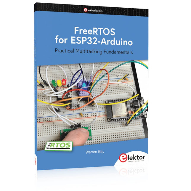
Elektor Publishing FreeRTOS for ESP32-Arduino
Practical Multitasking Fundamentals Programming embedded systems is difficult because of resource constraints and limited debugging facilities. Why develop your own Real-Time Operating System (RTOS) as well as your application when the proven FreeRTOS software is freely available? Why not start with a validated foundation? Every software developer knows that you must divide a difficult problem into smaller ones to conquer it. Using separate preemptive tasks and FreeRTOS communication mechanisms, a clean separation of functions is achieved within the entire application. This results in safe and maintainable designs. Practicing engineers and students alike can use this book and the ESP32 Arduino environment to wade into FreeRTOS concepts at a comfortable pace. The well-organized text enables you to master each concept before starting the next chapter. Practical breadboard experiments and schematics are included to bring the lessons home. Experience is the best teacher. Each chapter includes exercises to test your knowledge. The coverage of the FreeRTOS Application Programming Interface (API) is complete for the ESP32 Arduino environment. You can apply what you learn to other FreeRTOS environments, including Espressif’s ESP-IDF. The source code is available from GitHub. All of these resources put you in the driver’s seat when it is time to develop your next uber-cool ESP32 project. What you will learn: How preemptive scheduling works within FreeRTOS The Arduino startup “loopTask” Message queues FreeRTOS timers and the IDLE task The semaphore, mutex, and their differences The mailbox and its application Real-time task priorities and its effect Interrupt interaction and use with FreeRTOS Queue sets Notifying tasks with events Event groups Critical sections Task local storage The gatekeeper task
€ 49,95
Members: € 44,96
-

FNIRSI FNIRSI FNB58 USB Tester (with Bluetooth)
The FNIRSI FNB58 USB tester (with Bluetooth) is a comprehensive and very accurate USB voltage and current meter. It features a 2.0-inch full-color HD TFT display, built-in USB-A, micro USB and USB-C interface. With this device you can measure the power supply or power consumption of products or the charging power of cell phones and power supplies. You can also determine the fast charging protocol of chargers. Features USB-A and USB-C interface 2.0" HD display Data at a glance Wide compatibility Ultra-precise data detection Play with fast charging technology Automatic protocol detection (PD2.0, 3.0, 3.1, PPS, QC2.0, 3.0, FCP, SCP, AFC, PE, DASH VOOC, SuperVOOC and more) Simple user interface, easy to operate 4 function curve displays (real-time voltage and current curve, offline curve recording, D+/D- voltage curve, high-speed power supply ripple measurement) Cable detection 10 groups of energy recording battery capacity calculation PC connectivity for data logging and firmware updates Bluetooth app for Android devices Specifications Voltage range 4-28 V Current range 0-7 A Power range 0-120 W Load equivalent internal resistance 0-9999.9 Ω D+/D- voltage 0-3.3 V Capacity 0-9999.99 Ah Power consumption 0-9999.99 Wh Cable resistance 0-9999.9 Ω Interfaces micro USB, USB-A, USB-C Dimensions 42 x 13 x 82 mm Downloads Manual Firmware V0.68
€ 49,95
-
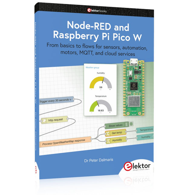
Elektor Publishing Node-RED and Raspberry Pi Pico W
From basics to flows for sensors, automation, motors, MQTT, and cloud services This book is a learning guide and a reference. Use it to learn Node-RED, Raspberry Pi Pico W, and MicroPython, and add these state-of-the-art tools to your technology toolkit. It will introduce you to virtual machines, Docker, and MySQL in support of IoT projects based on Node-RED and the Raspberry Pi Pico W. This book combines several elements into a platform that powers the development of modern Internet of Things applications. These elements are a flow-based server, a WiFi-enabled microcontroller, a high-level programming language, and a deployment technology. Combining these elements gives you the tools you need to create automation systems at any scale. From home automation to industrial automation, this book will help you get started. Node-RED is an open-source flow-based development tool that makes it easy to wire together devices, APIs, and online services. Drag and drop nodes to create a flowchart that turns on your lights at sunset or sends you an email when a sensor detects movement. Raspberry Pi Pico W is a version of the Raspberry Pi Pico with added 802.11n Wi-Fi capability. It is an ideal device for physical computing tasks and an excellent match to the Node-RED. Quick book facts Project-based learning approach. Assumes no prior knowledge of flow-based programming tools. Learn to use essential infrastructure tools in your projects, such as virtual machines, Docker, MySQL and useful web APIs such as Google Sheets and OpenWeatherMap. Dozens of mini-projects supported by photographs, wiring schematics, and source code. Get these from the book GitHub repository. Step-by-step instructions on everything. All experiments are based on the Raspberry Pi Pico W. A Wi-Fi network is required for all projects. Hardware (including the Raspberry Pi Pico W) is available as a kit. Downloads GitHub
€ 49,95
Members: € 44,96
-
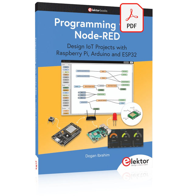
Elektor Digital Programming with Node-RED (E-book)
Design IoT Projects with Raspberry Pi, Arduino and ESP32 The Internet of Things (IoT) is becoming a major application area for embedded systems. As a result, more and more people are becoming interested in learning about embedded design and programming. Technical colleges and universities are moving away from legacy 8 and 16-bit microcontrollers and are introducing 32-bit embedded microcontrollers to their curriculums. Many IoT applications demand precision, high processing power, and low power consumption. Produced by IBM, Node-RED is an open-source visual editor for wiring the Internet of Things. Node-RED comes with a large number of nodes to handle a multitude of tasks. The required nodes are selected and joined together to perform a particular task. Node-RED is based on flow type programming where nodes are configured and joined together to form an application program. There are nodes for performing complex tasks, including web access, Twitter, E-mail, HTTP, Bluetooth, MQTT, controlling GPIO ports, etc. One particularly nice aspect of Node-RED is that the programmer does not need to learn how to write complex programs. For example, an email can be sent by simply joining nodes together and writing only a few lines of code. The aim of this book is to teach how Node-RED can be used in projects. The main hardware platform used with most of the projects in this book is Raspberry Pi 4. Chapters are included to show how Node-RED can be also be used with Arduino Uno, ESP32 DevKitC, and the ESP8266 NodeMCU microcontroller development boards.
€ 34,95
Members: € 31,46
-

Elektor Publishing FreeCAD for Electronics Applications
Practical Introduction to 3D Modeling from Enclosure to Front Panel Embedding a vintage component, creating a professional looking home for a circuit board, or even designing a complex apparatus complete with a chassis – these and many other challenges turn into a stimulating pleasure with FreeCAD. Once you have internalized the basic processes, there are virtually no limits to your imagination. Starting to use a new software is never straightforward – especially with a tool as versatile as FreeCAD. Manageable, but at the same time easily usable individual components provide the starting point in this book. Putting these components together later results in assemblies. In the FreeCAD universe, a workable trajectory is demonstrated. The described procedure is illustrative so the examples are easily applied to custom tasks. The devices were made by the author and illustrated with photos. Creating a 3D design is requiring some effort but the initial investment pays off soon. Besides the impressive spatial representation of the projects, the extracted drawings yield a solid base for documentation and production. Extended FreeCAD capabilities like the unfolding of sheet metal parts enormously add to efficiency and pushes models forward into practical assembly. Soon you will definitely not want to do without FreeCAD!
€ 44,95
Members: € 40,46
-

Elektor Bundles 555 Timer Projects (Bundle)
This bundle is all about designing projects based on the 555 timer IC. The book features over 45 fully tested and documented projects. Together with the kit, which contains more than 130 through-hole components, you can build all the projects described on a breadboard. The setup also makes it easy to modify and experiment with the projects. Over 45 Builds for the Legendary 555 Chip (and the 556, 558) Some of the projects in the book are: Alternately Flashing Two LEDs Changing LED Flashing Rate Touch Sensor On/Off Switch Switch On/Off Delay Light-Dependent Sound Dark/Light Switch Tone Burst Generator Long Duration Timer Chasing LEDs LED Roulette Game Traffic Lights Continuity Tester Electronic Lock Switch Contact Debouncing Toy Electronic Organ Multiple Sensor Alarm System Metronome Voltage Multipliers Electronic Dice 7-Segment Display Counter Motor Control 7-Segment Display Dice Electronic Siren Various Other Projects Kit Contents Resistors 1x 15 kΩ 1x 68 kΩ 2x 47 kΩ 1x 82 kΩ 2x 820 Ω 1x 8.2 kΩ 3x 10 kΩ 1x 1.8 kΩ 1x 6.8 kΩ 14x 2.2 kΩ 10x 680 Ω 1x 27 kΩ 1x 5.6 kΩ 1x 560 kΩ 1x 4.7 kΩ 1x 3.3 kΩ 3x 33 kΩ 1x 36 kΩ 2x 100 kΩ 5x 1 kΩ 1x 3.9 kΩ 2x 56 kΩ 2x 12 kΩ 1x 10 kΩ potentiometer 1x 1 MΩ potentiometer 2x 50 kΩ potentiometer 3x 20 kΩ potentiometer 1x 10 kΩ potentiometer 1x 10 kΩ potentiometer 1x 50 kΩ potentiometer 1x 100 kΩ potentiometer 1x 50 kΩ potentiometer Capacitors 1x 0.33 μF 1x 1 μF 1x 10 nF 1x 22 nF 1x 47 nF 1x 100 nF 1x 10 μF electrolytic 1x 33 μF electrolytic 2x 100 μF electrolytic LEDs 10x 5 mm red LED 10x 3 mm red LED 3x 3 mm yellow LED 3x 3 mm green LED 1x Common-cathode 7-segment LED Semiconductors 3x 555 timer 1x CD4017 counter 1x CD4026 counter 1x CD4011 NAND gate 4x 1N4148 diode 1x IRFZ46N MOSFET 1x Thermistor 1x Light dependent resistor (LDR) Miscellaneous 1x Passive buzzer 1x Active buzzer 1x SG90 servo 1x 8 Ω mini loudspeaker 1x 9 V DC brushed motor 1x 5 V relay 1x 9 V battery clip 7x Pushbutton switches 1x Breadboard 1x Breadboard jumper wires
€ 69,95€ 54,95Best Price
-

Elektor Bundles Arduino UNO Q (Bundle)
This bundle includes the Arduino UNO Q (2 GB) and the new book "Arduino UNO Q and AI". The Arduino UNO Q is the first UNO board with a hybrid dual-brain architecture, combining a powerful Linux processor with a real-time microcontroller – bringing advanced computing and precise control together on one board. Powered by a Qualcomm Dragonwing QRB2210 MPU running Debian Linux and a STM32U585 MCU for real-time tasks, the UNO Q is built for next-generation applications. From Edge Computing and AI to robotics and automation, it delivers high performance without sacrificing ease of use. Simply connect your peripherals and get started – no extra hardware required. Features Dual-core architecture: Linux MPU + real-time MCU Qualcomm Dragonwing QRB2210 with Debian Linux support STM32U585 microcontroller for deterministic control Runs Arduino sketches via Zephyr OS Ideal for AI, IoT, robotics, and industrial projects Specifications Microprocessor (MPU) Qualcomm Dragonwing QRB2210:Quad-core Arm Cortex-A53 @ 2.0 GHzAdreno GPU 3D graphics accelerator2× ISP (13 MP + 13 MP or 25 MP) @ 30 fps Microcontroller (MCU) STM32U585Arm Cortex-M33 up to 160 MHz2 MB flash memory786 KB SRAM RAM 2 GB LPDDR4 Power Supply From USB-C connector 5 V max at 3 AInput Voltage (VIN): 7-24 V Storage 16 GB eMMC USB 1× USB-C port with host/device role switching, power role switch and video output Connectivity Wi-Fi 5 (2.4/5 GHz) with onboard antennaBluetooth 5.1 with onboard antenna Interfaces I²C/I³CSPIPWMCANUARTPSSIGPIOJTAGADC Video Video output support via USB-CMIPI DSI pins on JMEDIA header Extra 4× RGB user-controllable LEDs8×13 Blue LED Matrix1× Qwiic connector voltage 3V3, I²C1× User push-buttonJCTL: MPU Remote Debug connector Audio Microphone IN / Headphone OUT / Line OUT on JMISC MPU Operating System Linux Debian OS with upstream support Real-time Operating System Arduino Core on Zephyr OS Containerization Docker and Docker Compose support Support Operating Systems for Arduino App Lab Windows: Windows 10 or later (64-bit)macOS: macOS 11 or later (64-bit)Linux: Ubuntu 22.04 or later, and Debian Trixie (64-bit) Dimensions 68.85 × 53.34 mm (UNO form factor) Downloads Datasheet User Manual Pinout Schematics Book: Arduino UNO Q and AI – Learn to Build Intelligent Embedded Systems Build smarter embedded systems with Arduino UNO Q. This book gives you the tools, knowledge, and confidence to turn ideas into intelligent, working solutions using the Arduino UNO Q platform. Discover how to build intelligent embedded systems with the Arduino UNO Q and AI. Unlock the full potential of the Arduino UNO Q, a next-generation platform that combines the real-time power of the STM32U585 microcontroller with the flexibility of a Qualcomm Dragonwing QRB2210 microprocessor. Learn how to rapidly prototype real-world applications using the Arduino IDE for low-level embedded control and Python in Arduino App Lab for high-level development. Build confidence through hands-on projects that guide you step by step from basic board features to complete working systems. Explore ready-to-use, AI based Arduino App Lab examples and see how they can jump-start your development and reduce time to deployment. Step into the world of Edge AI with a clear, practical introduction to Edge Impulse Studio—no prior AI experience required. Follow a complete, real-world workflow to create a Keyword Spotting AI application, covering data collection, model training, optimization, and on-device inference using the Edge Impulse Studio. Bridge the gap between embedded systems and machine learning and learn how to bring intelligence directly onto your hardware. Perfect for embedded engineers, educators, students, and makers looking to stay ahead in AI-enabled product development. This bundle contains: Arduino UNO Q (2 GB) (normal price: €50) Book: Arduino UNO Q and AI (normal price: €35)
€ 84,95€ 74,95Best Price
-
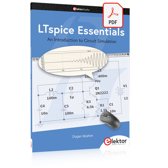
Elektor Digital LTspice Essentials (E-book)
An Introduction to Circuit Simulation LTspice, developed by Analog Devices, is a powerful, fast, and free SPICE simulator, schematic capture, and waveform viewer with a large database of components supported by SPICE models from all over the world. Drawing a schematic in LTspice is easy and fast. Thanks to its powerful graphing features, you can visualize the voltages and currents in a circuit, and also the power consumption of its components and much more. This book is about learning to design and simulate electronic circuits using LTspice. Among others, the following topics are treated: DC and AC circuits Signal diodes and Zener diodes Transistor circuits including oscillators Thyristor/SCR, diac, and triac circuits Operational amplifier circuits including oscillators The 555 timer IC Filters Voltage regulators Optocouplers Waveform generation Digital logic simulation including the 74HC family SPICE modeling LTspice is a powerful electronic circuit simulation tool with many features and possibilities. Covering them all in detail is not possible in a book of this size. Therefore, this book presents the most common topics like DC and AC circuit analysis, parameter sweeping, transfer functions, oscillators, graphing, etc. Although this book is an introduction to LTspice, it covers most topics of interest to people engaged in electronic circuit simulation. The book is aimed at electronic/electrical engineers, students, teachers, and hobbyists. Many tested simulation examples are given in the book. Readers do not need to have any computer programming skills, but it will help if they are familiar with basic electronic circuit design and operation principles. Readers who want to dive deeper can find many detailed tutorials, articles, videos, design files, and SPICE circuit models on the Internet. All the simulation examples used in the book are available as files at the webpage of this book. Readers can use these example circuits for learning or modify them for their own applications.
€ 32,95
Members: € 29,66
-
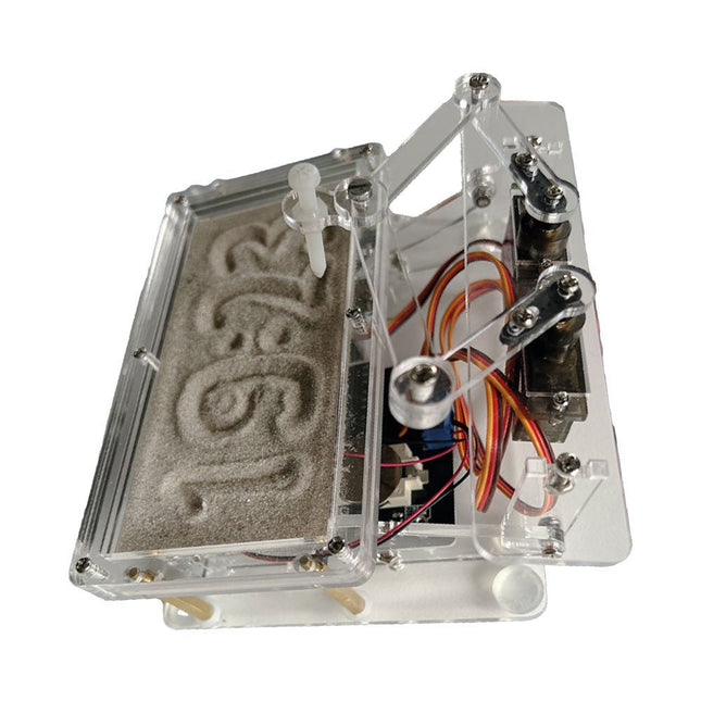
Elektor Labs Elektor Sand Clock for Raspberry Pi Pico
Raspberry Pi-based Eye Catcher A standard sand clock just shows how time passes. In contrast, this Raspberry Pi Pico-controlled sand clock shows the exact time by “engraving” the four digits for hour and minute into the layer of sand. After an adjustable time the sand is flattened out by two vibration motors and everything begins all over again. At the heart of the sand clock are two servo motors driving a writing pen through a pantograph mechanism. A third servo motor lifts the pen up and down. The sand container is equipped with two vibration motors to flatten the sand. The electronic part of the sand clock consists of a Raspberry Pi Pico and an RTC/driver board with a real-time clock, plus driver circuits for the servo motors. A detailed construction manual is available for downloading. Features Dimensions: 135 x 110 x 80 mm Build time: approx. 1.5 to 2 hours Included 3x Precut acrylic sheets with all mechanical parts 3x Mini servo motors 2x Vibration motors 1x Raspberry Pi Pico 1x RTC/driver board with assembled parts Nuts, bolts, spacers, and wires for the assembly Fine-grained white sand
€ 49,95€ 39,95Best Price
-

Elektor Digital FreeRTOS for ESP32-Arduino (E-book)
Practical Multitasking Fundamentals Programming embedded systems is difficult because of resource constraints and limited debugging facilities. Why develop your own Real-Time Operating System (RTOS) as well as your application when the proven FreeRTOS software is freely available? Why not start with a validated foundation? Every software developer knows that you must divide a difficult problem into smaller ones to conquer it. Using separate preemptive tasks and FreeRTOS communication mechanisms, a clean separation of functions is achieved within the entire application. This results in safe and maintainable designs. Practicing engineers and students alike can use this book and the ESP32 Arduino environment to wade into FreeRTOS concepts at a comfortable pace. The well-organized text enables you to master each concept before starting the next chapter. Practical breadboard experiments and schematics are included to bring the lessons home. Experience is the best teacher. Each chapter includes exercises to test your knowledge. The coverage of the FreeRTOS Application Programming Interface (API) is complete for the ESP32 Arduino environment. You can apply what you learn to other FreeRTOS environments, including Espressif’s ESP-IDF. The source code is available from GitHub. All of these resources put you in the driver’s seat when it is time to develop your next uber-cool ESP32 project. What you will learn: How preemptive scheduling works within FreeRTOS The Arduino startup “loopTask” Message queues FreeRTOS timers and the IDLE task The semaphore, mutex, and their differences The mailbox and its application Real-time task priorities and its effect Interrupt interaction and use with FreeRTOS Queue sets Notifying tasks with events Event groups Critical sections Task local storage The gatekeeper task
€ 39,95
Members: € 35,96
-

Elektor Publishing The Book of 555 Timer Projects
Over 45 Builds for the Legendary 555 Chip (and the 556, 558) The 555 timer IC, originally introduced by the Signetics Corporation around 1971, is sure to rank high among the most popular analog integrated circuits ever produced. Originally called the IC Time Machine, this chip has been used in many timer-related projects by countless people over decades. This book is all about designing projects based on the 555 timer IC. Over 45 fully tested and documented projects are presented. All projects have been fully tested by the author by constructing them individually on a breadboard. You are not expected to have any programming experiences for constructing or using the projects given in the book. However, it’s definitely useful to have some knowledge of basic electronics and the use of a breadboard for constructing and testing electronic circuits. Some of the projects in the book are: Alternately Flashing Two LEDs Changing LED Flashing Rate Touch Sensor On/Off Switch Switch On/Off Delay Light-Dependent Sound Dark/Light Switch Tone Burst Generator Long Duration Timer Chasing LEDs LED Roulette Game Traffic Lights Continuity Tester Electronic Lock Switch Contact Debouncing Toy Electronic Organ Multiple Sensor Alarm System Metronome Voltage Multipliers Electronic Dice 7-Segment Display Counter Motor Control 7-Segment Display Dice Electronic Siren Various Other Projects The projects given in the book can be modified or expanded by you for your very own applications. Electronic engineering students, people engaged in designing small electronic circuits, and electronic hobbyists should find the projects in the book instructive, fun, interesting, and useful.
€ 34,95
Members: € 31,46
-
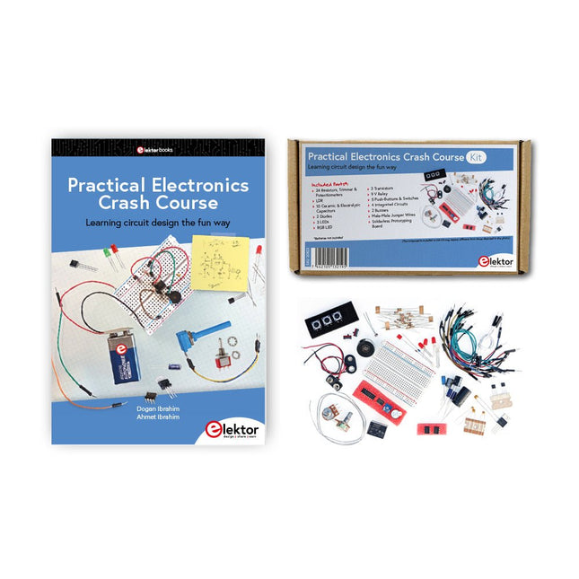
Elektor Bundles Practical Electronics Crash Course (Bundle)
Getting started in electronics is not as difficult as you may think. With this bundle (book + kit of parts), you can explore and learn the most important electrical and electronics engineering concepts in a fun way by doing various experiments. You will learn electronics practically without getting into complex technical jargon and long calculations. As a result, you will be creating your own projects soon. This kit contains the components required to build most of the detailed examples of the book on a breadboard and try them out for real. The kit can, of course, also be used without the book for building other circuits and doing your own experiments. Kit contents 1x 39 Ω, 1 W resistor 1x 47 Ω resistor 1x 180 Ω resistor 1x 330 Ω resistor 3x 1 kΩ resistor 1x 2.2 kΩ resistor 1x 3.9 kΩ resistor 1x 6.8 kΩ resistor 1x 10 kΩ resistor 1x 15 kΩ resistor 1x 22 kΩ resistor 1x 33 kΩ resistor 1x 47 kΩ resistor 1x 56 kΩ resistor 1x 82 kΩ resistor 1x 120 kΩ resistor 1x 680 kΩ resistor 2x 100 kΩ resistor 1x 10 kΩ trimmer 1x 10 kΩ linear potentiometer 1x 100 kΩ linear potentiometer 1x LDR 1x 1 nF ceramic capacitor 2x 10 nF ceramic capacitor 1x 100 nF ceramic capacitor 1x 1 µF, 25 V aluminium electrolytic capacitor 2x 10 µF, 25 V aluminium electrolytic capacitor 1x 100 µF, 25 V aluminium electrolytic capacitor 1x 470 µF, 25 V aluminium electrolytic capacitor 1x 1000 µF, 25 V aluminium electrolytic capacitor 1x RGB LED, Common-Cathode (CC) 1x 1N4148 small signal diode 1x 1N4733A 5.1 V, 1 W Zener diode 3x LED, red 2x BC337 NPN transistor 1x IRFZ44N N-channel MOSFET 2x NE555 timer 1x LM393 comparator 1x 74HCT08 quad AND gate 3x Tactile switch 2x SPDT switch 1x Relay, SPDT, 9 VDC 1x Active buzzer 1x Passive buzzer 50 cm Solid wire, 16 AWG, unjacketed 2x PP3 9 V battery clip 1x Breadboard 20x Jumper wire This bundle contains: Practical Electronics Crash Course Kit (valued at: €45) Book: Practical Electronics Crash Course (normal price: €45)
€ 89,95€ 69,95Best Price
-
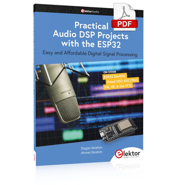
Elektor Digital Practical Audio DSP Projects with the ESP32 (E-book)
Easy and Affordable Digital Signal ProcessingThe aim of this book is to teach the basic principles of Digital Signal Processing (DSP) and to introduce it from a practical point of view using the bare minimum of mathematics. Only the basic level of discrete-time systems theory is given, sufficient to implement DSP applications in real time. The practical implementations are described in real time using the highly popular ESP32 DevKitC microcontroller development board. With the low cost and extremely popular ESP32 microcontroller, you should be able to design elementary DSP projects with sampling frequencies within the audio range. All programming is done using the popular Arduino IDE in conjunction with the C language compiler.After laying a solid foundation of DSP theory and pertinent discussions on the main DSP software tools on the market, the book presents the following audio-based sound and DSP projects: Using an I²S-based digital microphone to capture audio sound Using an I²S-based class-D audio amplifier and speaker Playing MP3 music stored on an SD card through an I²S-based amplifier and speaker Playing MP3 music files stored in ESP32 flash memory through an I²S-based amplifier and speaker Mono and stereo Internet radio with I²S-based amplifiers and speakers Text-to-speech output with an I²S-based amplifier and speaker Using the volume control in I²S-based amplifier and speaker systems A speaking event counter with an I²S-based amplifier and speaker An adjustable sinewave generator with I²S-based amplifier and speaker Using the Pmod I²S2 24-bit fast ADC/DAC module Digital low-pass and band-pass real-time FIR filter design with external and internal A/D and D/A conversion Digital low-pass and band-pass real-time IIR filter design with external and internal A/D and D/A conversion Fast Fourier Transforms (FFT)
€ 32,95
Members: € 29,66
-

Elektor Classics The Elektor Arduino Collection (USB Stick)
This USB Stick contains more than 300 Arduino-related articles published in Elektor Magazine. The content includes both background articles and projects on the following topics: Software & hardware development: Tutorials on Arduino software development using Arduino IDE, Atmel Studio, Shields, and essential programming concepts. Learning: The Microcontroller Bootcamp offers a structured approach to programming embedded systems. Data acquisition & measurement: Projects such as a 16-bit data logger, lathe tachometer, and an AC grid analyzer for capturing and analyzing real-time signals. Wireless communication: Learn how to implement wireless networks, create an Android interface, and communicate effectively with microcontrollers. Robotics and automation: This covers the Arduino Nano Robot Controller, supporting boards for automation, and explores various Arduino shields to enhance functionality. Self-build projects: Unique projects such as laser projection, Numitron clock and thermometer, ELF receiver, Theremino, and touch LED interfaces highlight creative applications. Whether you're a beginner or an experienced maker, this collection is a valuable resource for learning, experimenting, and pushing the boundaries of Arduino technology.
€ 49,95€ 34,95Best Price
-
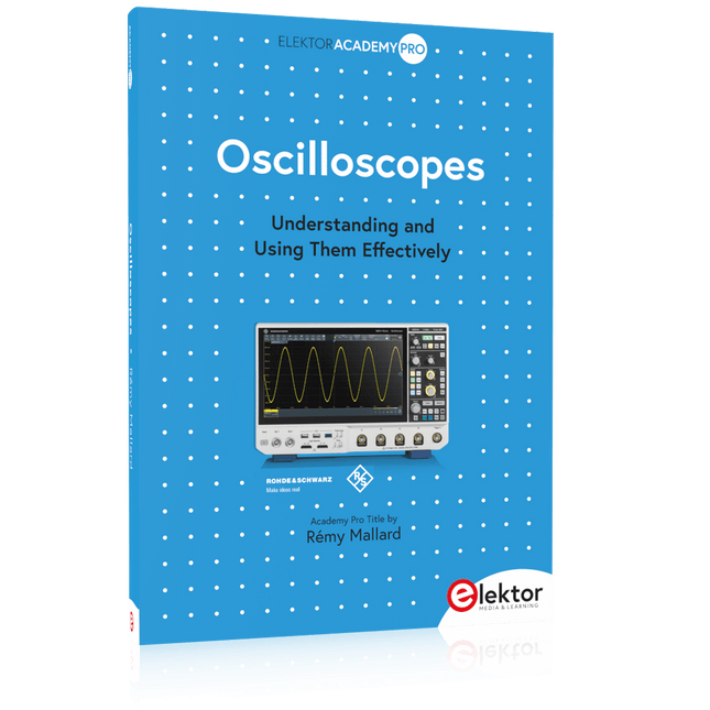
Elektor Publishing Oscilloscopes (Book)
Understanding and Using Them Effectively What happens in electronics is invisible to the naked eye. The instrument that allows to accurately visualize electrical signals, the one through which the effects of electronics become apparent to us, is the oscilloscope. Alas, when one first ventures into electronics, it is often without an oscilloscope. And one is left fumbling, both physically and mentally. Observing an electrical signal on a screen for the first time is a revelation. Nobody wishes to forgo that marvel again. There is no turning back. In electronics, if one wishes to progress with both enjoyment and understanding, an oscilloscope is essential. This marks the beginning of a period of questioning: how to choose one? And no sooner is that question answered than a whole string of others arises, which can be summed up in just one: how does one use the oscilloscope in such a way that what it displays truly reflects the reality of the signals? Rémy Mallard is a passionate communicator with a gift for making complex technical subjects understandable and engaging. In this book, he provides clear answers to essential questions about using an oscilloscope and offers a wealth of guidance to help readers explore and understand the electrical signals behind electronic systems. With his accessible style and practical insights, this book is a valuable tool for anyone eager to deepen their understanding of electronics.
€ 44,95
Members: € 40,46


