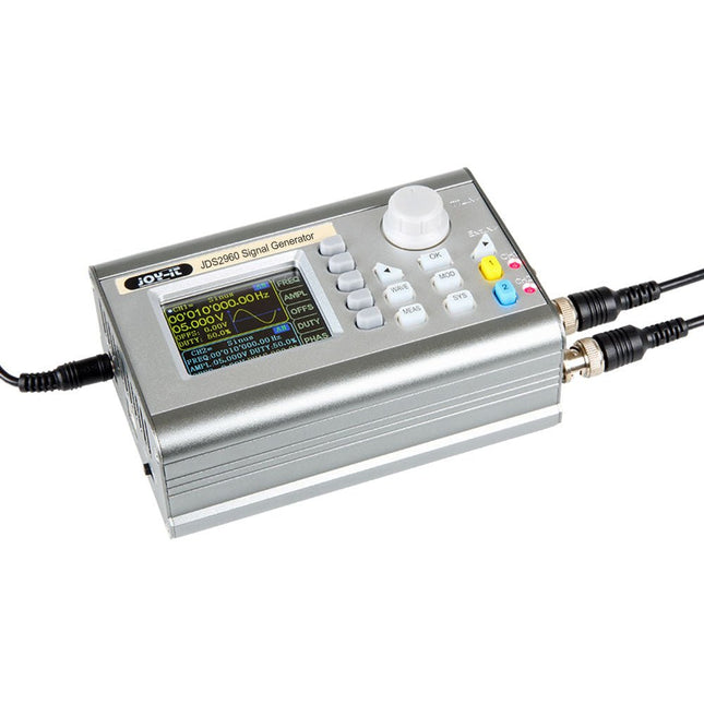
The JOY-iT JDS2960 is a 2-channel signal generator capable of producing signals up to 60 MHz. Its compact design and the option to operate it with a power bank make it ideal for mobile use.
With a variety of waveforms, including sine, square, triangle, pulse, half-wave, and more, it is suitable for various measurement technology applications.
Additionally, the JDS2960 features a 1-channel frequency allocation. Its high frequency accuracy of ±20 ppm and stability of ±1 ppm/3 h ensure excellent signal quality and great flexibility.
The 2.4-inch TFT color display provides user-friendly operation and enables a wide range of applications.
Features
2 Channels
Up to 60 MHz
Robust aluminum housing
1-channel frequency counter
Up to 20 Vpp
Many different pre-programmed waveforms and up to 60 user-defined waveforms
Pulse function
Specifications
Channels
2-channel Signal Generator1-channel Frequency meter
Frequency range
Sine: 0-60 MHzSquare, triangle: 0-25 MHzTTL, Pulse: 0-6 MHz
Signal forms
Sine, square, triangle, pulse, half/solid wave, exponential rise/fall, etc.
Measuring range frequency counter
1-100 MHz
Frequency accuracy
±20 ppm
Frequency stability
±1 ppm/3 h
Sampling rate
266 MSa/s
Display
2,4" TFT color LCD
Vertical shaft resolution
14 bits
Amplitude range
<10 MHz: 0-20 Vpp>10 MHz: 0-10 Vpp
Amplitude resolution
1 mV
Amplitude stability
±5%/5h
Amplitude flatness
<10 MHz: ±5%>10 MHz: ±10%
Impedance of output
50 Ω ±10%
Distortion factor
<0.8% (20 Hz-20 KHz, 0 dBm)
Dimensions
145 x 95 x 55 mm
Weight
900 g
Included
1x JOY-iT JDS2960 2-ch Signal Generator
1x Power supply unit
1x BNC-BNC cable
2x BNC crocodile clip cables
1x USB-DC power cable
1x USB data cable
Downloads
Datasheet
Manual
Software
Microcontrollers have become an indispensable part of modern electronics. They make things possible that vastly exceed what could be done previously. Innumerable applications show that almost nothing is impossible.
There’s thus every reason to learn more about them, but that raises the question of where to find a good introduction to this fascinating technology. The answer is easy: this Microcontroller Basics book, combined with the 89S8252 Flash Board project published by Elektor Electronics.
However, this book offers more than just a basic introduction. It clearly explains the technology using various microcontroller circuits and programs written in several different programming languages. Three microcontrollers from the 8051 family are used in the sample applications, ranging from the simple 89C2051 to the AN2131, which is designed to support USB applications. The programming tools include assemblers, Basic-52 and BASCOM-51, and several C compilers. Every reader can thus find the programming environment most suitable to his or her needs.
In the course of the book, the reader gradually develops increased competence in converting his or her ideas into microcontroller circuitry. All of the sample programs can be downloaded from the Elektor Electronics website or the author’s website. That has the added advantage that the latest versions are always available.
The Piccolino rapid development board can be used to design microcontroller circuits quickly. The Piccolino has a fast 16f887 PIC microcontroller, voltage regulator, and communications module, and can be easily extended using its four headers.
This e-book contains 30 projects based on the Piccolino. We'll use its unique communications facilities and get the Piccolino to communicate with programs on a PC. On the PC, we use the free programming language Small Basic. You can use this to create Windows programs with buttons and graphs quickly. You will learn how to analyze components such as inductors, capacitors, and OPAMPs, and how to display the measurement results in a graphical format. This will help you to design your circuits easily.
We will then start to adapt to the Piccolino. We'll add components to it to make it more powerful, with extra features such as flow control and digital to analog conversion. The clear instructions will enable you to design and build your adaptations. This way you can make your custom designed Piccolino.
We'll end up making an extension: a PCB that that can be mounted on the Piccolino headers. As an example, we'll design and build an extension for an LCD. You can use the included board layout to make your PCB or have it made for you. At the same time, you will learn how to make your extensions. The only limitation is your imagination!
The clear descriptions along with circuit diagrams and photos, will make the building of these projects an enjoyable experience. Each project has a clear explanation of the reasons why it was designed in a particular way. This helps you learn a lot about the Piccolino, as well as Small Basic, and the components that are used in this e-book. You can adapt the projects to suit your requirements or combine several projects.
The newcomer to Microchip’s PIC microcontrollers invariably gets an LED to flash as their first attempt to master this technology. You can use just a simple LED indicator in order to show that your initial attempt is working, which will give you confidence to move forward. This is how the book begins — simple programs to flash LEDs, and eventually by stages to use other display indicators such as the 7-segment display, alphanumeric liquid crystal displays and eventually a colour graphic LCD.
As the reader progresses through the book, bigger and upgraded PIC chips are introduced, with full circuit diagrams and source code, both in assembler and C.
In addition, a small tutorial is included using the MPLAB programming environment, together with the EAGLE schematic and PCB design package to enable readers to create their own designs using the book’s many case studies as working examples to work from.
The present tenth edition of the popular ʻ30x Circuitsʼ series of books once again contains a comprehensive variety of circuits, sub-circuits, tips and tricks and design ideas for electronics. These 309 Circuits again offer a representative indication of present-day electronics.
Regular ʻ30x seriesʼ enthusiasts will no doubt know what to expect: 309 Circuits contains many fully elaborated electronics projects. In addition, there are numerous ideas, each of which with a potential for use in your own research, projects and applications.
Among many other inspiring topics, the following categories are well presented in this book: test & measurement; RF (radio); computers and peripherals; audio & video; hobby and modelling; microcontrollers; home & garden; power supplies & battery chargers; etcetera.
309 Circuits has been compiled from the contents of Elektor Electronics' Summer Circuits editions for the years 2003, 2004 and 2005. Summer Circuits is the annual double issue of Elektor Electronics magazine covering the months of July and August.
LuckFox Pico Mini is a compact Linux micro development board based on the Rockchip RV1103 chip, providing a simple and efficient development platform for developers. It supports a variety of interfaces, including MIPI CSI, GPIO, UART, SPI, I²C, USB, etc., which is convenient for quick development and debugging.
Features
Single-core ARM Cortex-A7 32-bit core with integrated NEON and FPU
Built-in Rockchip self-developed 4th generation NPU, features high computing precision and supports int, int8, and int16 hybrid quantization. The computing power of int8 is 0.5 TOPS, and up to 1.0 TOPS with int4
Built-in self-developed third-generation ISP3.2, supports 4-Megapixel, with multiple image enhancement and correction algorithms such as HDR, WDR, multi-level noise reduction, etc.
Features powerful encoding performance, supports intelligent encoding mode and adaptive stream saving according to the scene, saves more than 50% bit rate of the conventional CBR mode so that the images from camera are high-definition with smaller size, double the storage space
Built-in RISC-V MCU supports low power consumption and fast start-up, supports 250 ms fast picture capture and loading Al model library at the same time to realize face recognition "in one second"
Built-in 16-bit DRAM DDR2, which is capable of sustaining demanding memory bandwidths
Integrated with built-in POR, audio codec and MAC PHY
Specifications
Processor
ARM Cortex-A7, single-core 32-bit CPU, 1.2 GHz, with NEON and FPU
NPU
Rockchip 4th-gen NPU, supports int4, int8, int16; up to 1.0 TOPS (int4)
ISP
Third-gen ISP3.2, up to 4 MP input at 30fps, HDR, WDR, noise reduction
RAM
64 MB DDR2
Storage
128 MB SPI NAND Flash
USB
USB 2.0 Host/Device via Type-C
Camera Interface
MIPI CSI 2-lane
GPIO Pins
17 GPIO pins
Power Consumption
Low power, RISC-V MCU for fast startup
Dimensions
28 x 21 mm
Downloads
Wiki
The FRDM-MCXN947 is a compact and versatile development board designed for rapid prototyping with MCX N94 and N54 microcontrollers. It features industry-standard headers for easy access to the MCU's I/Os, integrated open-standard serial interfaces, external flash memory, and an onboard MCU-Link debugger.
Specifications
Microcontroller
MCX-N947 Dual Arm Cortex-M33 cores @ 150 MHz each with optimized performance efficiency, up to 2 MB dual-bank flash with optional full ECC RAM, External flash
Accelerators: Neural Processing Unit, PowerQuad, Smart DMA, etc.
Memory Expansion
*DNP Micro SD card socket
Connectivity
Ethernet Phy and connector
HS USB-C connectors
SPI/I²C/UART connector (PMOD/mikroBUS, DNP)
WiFi connector (PMOD/mikroBUS, DNP)
CAN-FD transceiver
Debug
On-board MCU-Link debugger with CMSIS-DAP
JTAG/SWD connector
Sensor
P3T1755 I³C/I²C Temp Sensor, Touch Pad
Expansion Options
Arduino Header (with FRDM expansion rows)
FRDM Header
FlexIO/LCD Header
SmartDMA/Camera Header
Pmod *DNP
mikroBUS
User Interface
RGB user LED, plus Reset, ISP, Wakeup buttons
Included
1x FRDM-MCXN947 Development Board
1x USB-C Cable
1x Quick Start Guide
Downloads
Datasheet
Block diagram
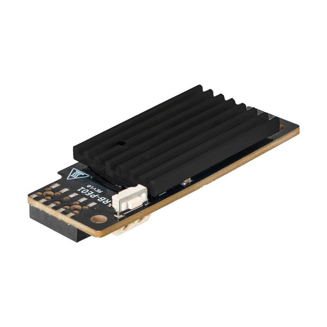
Wide Range Power Supply for Raspberry Pi
With the PiEnergy Mini, you can operate your Raspberry Pi with a voltage of 6 to 36 V DC. You can use the button integrated on the board to both power up and power down your Raspberry Pi.
Communication with the Raspberry Pi is via GPIO4, but this connection can also be cut by removing a resistor to use the pin freely. Thanks to the ultra-flat design, it can also be used in many housings. The pin header is included and not soldered on to keep the design even flatter.
Specifications
Input voltage
6 to 36 V DC
Output voltage
5.1 V
Output current
Up to 3 A (active ventilation recommended for additionally connected loads)
Cable cross-section at the power input
0.2-0.75 mm²
Interface to the Raspberry Pi
GPIO4
Microcontroller
ATtiny5
Further connections
5 V fan connector (2-pin/2.54 mm)Solder pads for external on/off switch
Compatible with
Raspberry Pi 3, 4, 5
Dimensions
23 x 56 x 11 mm
Included
Board with mounted heat sink
Pin header (2x5)
Spacer, screw, nut
Downloads
Datasheet (English)
Datasheet (Italiano)
Manual (English)
Manual (Italiano)
This 5.83-inch black/white e-paper e-ink display module for Raspberry Pi Pico offers a resolution of 648 × 480 pixels, an SPI interface, low power consumption, wide viewing angle and a paper-like effect without electricity.
Features
No backlight, keeps displaying last content for a long time even when power down
Ultra low power consumption, basically power is only required for refreshing
SPI interface, requires minimal I/O pins
2x user buttons and 1x reset button for easy interacting
Comes with development resources and manual (Raspberry Pi Pico C/C++ and MicroPython examples)
Specifications
Operating voltage
3.3 V
Display color
Black, white
Resolution
648 × 480 pixels
Gray scale
2
Interface
3-wire SPI, 4-wire SPI
Viewing angle
>170°
Partial refresh time
N/A
Full refresh time
5s
Outline dimensions
125.4 × 99.5 mm
Display size
119.232 × 88.320 mm
Refresh power
26.4 mW (typ.)
Standby current
<0.01 uA (almost none)
Dot pitch
0.184 × 0.184 mm
Applications
Suitable For Price Tags
Asset/Equipment Tags
Shelf Labels
Conference Name Tag
Included
1x 5.83-inch e-Paper
1x Pico-ePaper-Driver-Board
1x Standoff pack
Downloads
Wiki
This is a high-performance cooling solution designed to effectively dissipate heat and ensure optimal operating temperatures for the Raspberry Pi. It is an essential accessory for users who want to enhance the performance and longevity of their Raspberry Pi device.
The compact design of the Water cooling kit for Raspberry Pi 5 allows it to be seamlessly installed on the top and bottom of the Raspberry Pi 5, ensuring efficient heat transfer and perfectly protecting the bottom of the Raspberry Pi. Its simple installation process eliminates the need for complex wiring or additional tools, making it friendly to both beginners and experienced Raspberry Pi enthusiasts.
With its powerful cooling performance, the water cooling kit for Raspberry Pi 5 for effectively dissipates heat generated by the Raspberry Pi during intensive tasks or prolonged usage. This helps prevent overheating and ensures stable performance. Efficient water-cooled cooling will allow you to connect multiple Raspberry Pi boards to a set of cooling devices. When using Raspberry Pi in a cluster, you can use a set of water-cooled devices to effectively cool multiple Raspberry Pi boards.
Features
Made for Raspberry Pi: Specially designed for Raspberry Pi 5, 1:1 mold opening, covering all heat sources, including CPU, Wi-Fi, power chip, and eMMC.
Cooling Performance: Effectively dissipates the heat generated by the Raspberry Pi, ensuring optimal operating temperatures and preventing overheating.
Easy to Use: The integrated design of the water pump and cooling fan is convenient for users to install.
RGB Color Lighting: RGB-colored lights are installed at the fan and water pump locations.
Included
1x Water cooling kit
1x Water cooling radiator
1x Black heatsink
2x Silicone hose
1x 12 V/2 A power adapter (US)
4x Hexagonal screw M2.5x10
1x L-key hex wrench
An SMD Magazine rail holds up to eight SMD Magazines. A given rail can be used to hold a project-specific set of magazines indefinitely. Magazines are held at a right angle, ready to be picked and placed by Pixel Pump. Each SMD-Magazine Rail presents up to eight magazines at the perfect angle for you to pick and place their components using Pixel Pump. You can also use these rails to group components for specific projects. They are equipped with non-slip rubber feet and weighted for extra stability.
SMD Magazines are injection-molded containers and a great way to organize and consume SMD parts. They are custom built to store components and present them for picking. They can load up to 12-mm-wide, 9.5-mm tall tapes. They replace those hard-to-find plastic bags while being an excellent source of parts to pick and placing using Pixel Pump. Each SMD-Magazine Rail presents up to eight magazines at the perfect angle for you to pick and place their components using Pixel Pump. You can also use these rails to group components for specific projects. They are equipped with non-slip rubber feet and weighted for extra stability.
SMA Straight Plug to SMA Straight Plug, 76.2 mm
Specifications
Frequency range
0 to 18 GHz VSWR (≤1.35)
Insertion loss
≤0,22 db
Body
Brass Nickel
Centre contact
Brass Gold
Insulator
PTFE
Ever wanted an automated house? Or a smart garden? Well, now it’s easy with the Arduino IoT Cloud compatible boards. It means: you can connect devices, visualize data, control and share your projects from anywhere in the world. Whether you’re a beginner or a pro, we have a wide range of plans to make sure you get the features you need.
Connect your sensors and actuators over long distances harnessing the power of the LoRa wireless protocol or throughout LoRaWAN networks.
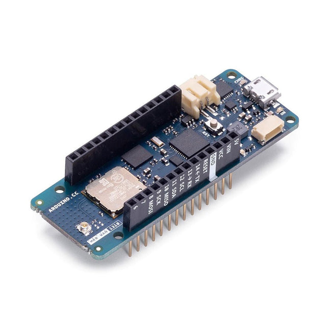
The Arduino MKR WAN 1310 board provides a practical and cost effective solution to add LoRa connectivity to projects requiring low power. This open source board can be connected to the Arduino IoT Cloud.
Better and More Efficient
The MKR WAN 1310, brings in a series of improvements when compared to its predecessor, the MKR WAN 1300. While still based on the Microchip SAMD21 low power processor, the Murata CMWX1ZZABZ LoRa module, and the MKR family’s characteristic crypto chip (the ECC508), the MKR WAN 1310 includes a new battery charger, a 2 MByte SPI Flash, and improved control of the board’s power consumption.
Improved Battery Power
The latest modifications have considerably improved the battery life on the MKR WAN 1310. When properly configured, the power consumption is now as low as 104 uA! It is also possible to use the USB port to supply power (5 V) to the board; run the board with or without batteries – the choice is yours.
On-board Storage
Data logging and other OTA (Over The Air) functions are now possible since the inclusion of the on board 2 MByte Flash. This new exciting feature will let you transfer configuration files from the infrastructure onto the board, create your own scripting commands, or simply store data locally to send it whenever the connectivity is best. Whilst the MKR WAN 1310’s crypto chip adds further security by storing credentials & certificates in the embedded secure element.
These features make it the perfect IoT node and building block for low-power wide-area IoT devices.
Specifications
The Arduino MKR WAN 1310 is based on the SAMD21 microcontroller.
Microcontroller
SAMD21 Cortex-M0+ 32-bit low power ARM MCU (datasheet)
Radio module
CMWX1ZZABZ (datasheet)
Board power supply (USB/VIN)
5 V
Secure element
ATECC508 (datasheet)
Supported batteries
Rechargeable Li-Ion, or Li-Po, 1024 mAh minimum capacity
Circuit operating voltage
3.3 V
Digital I/O pins
8
PWM pins
13 (0 .. 8, 10, 12, 18 / A3, 19 / A4)
UART
1
SPI
1
I²C
1
Analog input pins
7 (ADC 8/10/12 bit)
Analog output pins
1 (DAC 10 bit)
External interrupts
8 (0, 1, 4, 5, 6, 7, 8, 16 / A1, 17 / A2)
DC current per I/O pin
7 mA
CPU flash memory
256 KB (internal)
QSPI flash memory
2 MByte (external)
SRAM
32 KB
EEPROM
No
Clock speed
32.768 kHz (RTC), 48 MHz
LED_BUILTIN
6
USB
Full-Speed USB Device and embedded Host
Antenna gain
2 dB (bundled pentaband antenna)
Carrier frequency
433/868/915 MHz
Dimensions
67.64 x 25 mm
Weight
32 g
Downloads
Eagle Files
Schematics
Fritzing
Pinout
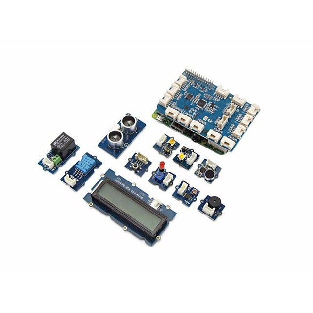
GrovePi+ is stacked on top of the Raspberry Pi without the need for any other connections. Communication between the two occurs over the I²C interface. All Grove modules connect to the universal Grove connectors on the GrovePi+ shield via the universal 4-pin connector cable.
Grove modules work on analog and digital signals and can be connected directly to the ATMEGA328 microcontroller on the Grove Pi+. The microcontroller acts as an interpreter between the Raspberry Pi and the Grove sensors. It sends, receives, and executes commands sent by the Raspberry Pi.
Features
One GrovePi+ board together with 12 popular Grove sensors and 10 Grove cables
GrovePi+ is compatible with Raspberry Pi A+, B, B+ / 2, 3, 4.
CE certified and compatible with Linux and Win 10 IoT.
Included
1x Grove Pi+
1x Grove - Rotary Angle Sensor
1x Grove - Sound Sensor
1x Grove - LCD RGB Backlight
1x Grove - Temp&Humi Sensor
1x Grove - Red LED
1x Grove - Light Sensor
1x Grove - Buzzer
1x Grove - Relay
1x Grove - Blue LED
1x Grove - Button
1x GrovePi+ Guidebook
10x Cables
1x Grove - UItrasonic Ranger
1x Grove - Green LED
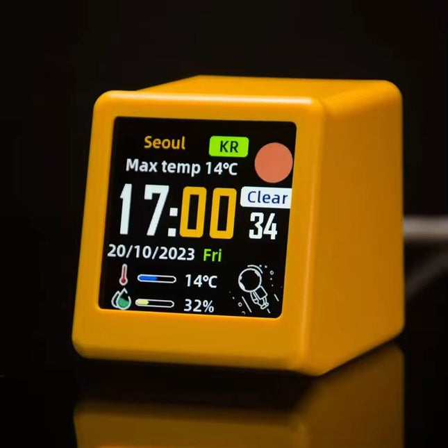
This portable WiFi weather station is the perfect blend of functionality and style, offering real-time updates on temperature, humidity, and time – all at a single glance.
Featuring a clear digital display, the station ensures that weather and time data are always easy to read and understand. Its minimalist design integrates seamlessly into any environment, adding a touch of modern sophistication without drawing unnecessary attention.
Features
Multi-Function Display: Shows weather, atmospheric pressure, min/max temperature, wind speed, city, country/region, date, day of the week, outdoor temperature & humidity – all at a glance.
Custom GIF Animations: Upload your own GIFs for a personalized display experience.
WiFi Connectivity: Automatically connects to the Internet to retrieve real-time weather and time data.
Power Supply: USB-C
Durable Plastic Casing
Dimensions: 45 x 35 x 40 mm
The SUNKKO 737G+ spot welder is a powerful and versatile tool designed for seamless and precise welding, particularly for 18650 battery packs. Prioritizing safety, it comes equipped with a 30 A fuse for 220 V, ensuring protection against potential electrical hazards, giving users peace of mind during use.
For enhanced adaptability, the welder offers the option of automatic or foot pedal control, allowing you to switch between modes based on your needs and preferences. Whether you're working on intricate projects or larger tasks, this flexibility ensures you have full control at all times.
With a robust 4.3 KW rated capacity, the SUNKKO 737G+ delivers the power needed for efficient and effective welding. Its advanced pulse control system features four pulse time settings ranging from 2 to 20 milliseconds, and eight extended pulse time settings between 8 and 80 milliseconds. This level of precision gives you the ability to tailor the welding process to each specific task, ensuring high-quality results every time.
Furthermore, the welder supports a maximum welding thickness of 0.35 mm, making it suitable for a variety of battery sizes and materials. This versatility, combined with its advanced features, makes the SUNKKO 737G+ an excellent choice for both professionals and hobbyists seeking reliable, efficient, and safe welding performance.
IMPORTANT: This device requires a 25 A circuit breaker. Do not use with a smaller circuit breaker!
Features
Max. power output: 4.3 kW (Instantaneous)
Input voltage: 220 V
Welding current: 120-1200 A
Single pulse time: 5 ms
Max. pulse quantity: 18
Fuse: 30 A
Max. welding thickness: 0.35 mm
Automatic spot welding
Foot pedal control welding
Dimensions: 14 x 25 x 20 cm
Weight: 7 kg
Included
1x 737G+ spot welding machine
1x S70BN mobile welding pen
1x Copper welding rods
1x Mini grinder with USB cable
1x Copper welding pins for mobile pen
1x Battery fixture
1x Foot pedal
2x Fuses
1x Hexagon wrench
50x Nickel plated steel (0.15 x 8 x 100 mm)
50x Nickel plated steel (0.1 x 4 x 100 mm)
1x Manual
Downloads
Manual
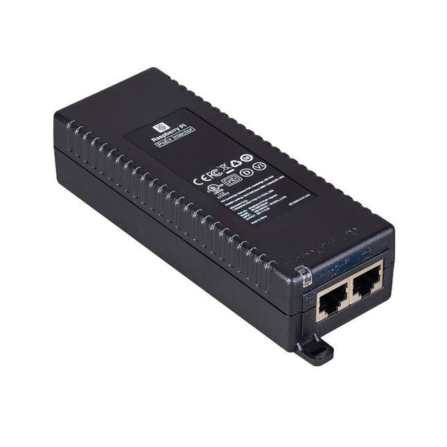
The Raspberry Pi PoE+ Injector adds Power-over-Ethernet (PoE) functionality to a single port of a non-PoE Ethernet switch, delivering both power and data through one Ethernet cable. It provides a plug-and-play, cost-effective solution for incrementally introducing PoE capability into existing Ethernet networks.
The PoE+ Injector is a single-port, 30 W device suitable for powering equipment compliant with IEEE 802.3af and 802.3at standards, including all generations of Raspberry Pi PoE HATs. It supports network pass-through speeds of 10/100/1000 Mbps.
Note: A separate IEC mains cable is required for operation (not included).
Specifications
Data rate
10/100/1000 Mbps
Input voltage
100 to 240 V AC
Output power
30 W
Power output on pins
4/5 (+), 7/8 (–)
Nominal output voltage
55 V DC
Data connectors
Shielded RJ-45, EIA 568A and 568B
Power connector
IEC c13 mains power input (not included)
Storage humidity
Maximum 95%, non-condensing
Operating altitude
–300 m to 3000 m
Operating ambient temperature
10°C to +50°C
Dimensions
159 x 51.8 x 33.5 mm
Downloads
Datasheet
The field of digital electronics is central to modern technology. This e-book presents fundamental circuits using gates, flip-flops and counters from the CMOS 4000 Series. Each of the 50 experiments has a circuit diagram as well as a detailed illustration of the circuit’s construction on solderless breadboard.
Learning these fundamentals is best done using practical experiments. Building these digital circuits will improve your knowledge and will be fun to boot. Many of the circuits presented here have practical real-life applications. With a good overview of the field, you’ll be well equipped to find simple and cost-effective solutions for any application.
The e-book is targeted essentially at students, trainees and anyone with an interest in and requiring an introduction to digital control electronics. Moreover, the knowledge gleaned here is the foundation for further projects in the field of microcontrollers and programming.
The Pimoroni Explorer Starter Kit is an electronic adventure playground for physical computing based on the RP2350 chip. It includes a 2.8-inch LCD screen, a speaker, a mini breadboard and much more. It's ideal for tinkering, experiments, and building small prototypes.
Features
Mini breadboard for wiring up components
Servo headers
Analog inputs
Built-in speaker
Plenty of general purpose inputs/outputs
Connectors for attaching crocodile leads
Qw/ST connectors for attaching I²C breakouts
Specifications
Powered by RP2350B (Dual Arm Cortex-M33 running at up to 150 MHz with 520 KB of SRAM)
16 MB of QSPI flash supporting XiP
2.8" IPS LCD screen (320 x 240 pixels)
Driver IC: ST7789V
Luminance: 250 cd/m²
Active area: 43.2 x 57.5 mm
USB-C connector for programming and power
Mini breadboard
Piezo speaker
6x user-controllable switches
Reset and boot buttons
Easy access GPIO headers (6x GPIOs and 3x ADCs, plus 3.3 V power and grounds)
6x Crocodile clip terminals (3x ADCs, plus 3.3 V power and grounds)
4x 3-pin servo outputs
2x Qw/ST (Qwiic/STEMMA QT) connector
2-pin JST-PH connector for adding a battery
Lanyard slot!
Includes 2x desktop stand feet
Fully-assembled (no soldering required)
Programmable with C/C++ or MicroPython
Included
1x Pimoroni Explorer
1x Multi-Sensor Stick – a fancy new all-in-one super sensor suite for environmental, light and movement sensing
Selection of different colored LEDs to get blinky with (including red, yellow, green, blue, white and RGB)
1x Potentiometer (for analog amusements)
3x 12 mm switches with different coloured caps
2x Continuous rotation servos
2x 60 mm wheels for attaching to your servos
1x AAA battery holder (batteries not included)
1x Velcro to stick the battery holder to the back of Explorer
20x Pin to pin and 20x pin to socket jumper wires for making connections on your breadboard
1x Qw/ST cable to plug in the Multi-Sensor Stick
1x Silicon USB-C cable
Downloads
GitHub
Schematic
The ATmega328 Uno Development Board (Arduino Uno compatible) is a microcontroller board based on the ATmega328.
It has 14 digital input/output pins (of which 6 can be used as PWM outputs), 6 analogue inputs, a 16 MHz ceramic resonator, a USB connection, a power jack, an ICSP header and a reset button.
It contains everything needed to support the microcontroller; connect it to a computer with a USB cable or power it with a AC-to-DC adapter or battery to get started.
Specifications
Microcontroller
ATmega328
Operating voltage
5 V DC
Input voltage (recommended)
7-12 V DC
Input voltage (limits)
6-20 V DC
Digital I/O pins
14 (of which 6 provide PWM output)
Analogue input pins
6
SRAM
2 kB (ATmega328)
EEPROM
1 kB (ATmega328)
Flash memory
32 kB (ATmega328) of which 0.5 kB used by bootloader
Clock speed
16 MHz
Downloads
Manual
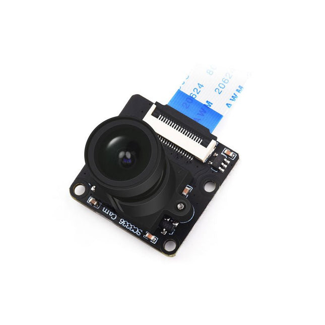
This camera module adopts a SmartSens SC3336 sensor chip with 3 MP resolution. It features high sensitivity, high SNR, and low light performance and it is capable of a more delicate and vivid night vision imaging effect, and can better adapt to ambient light changes. Also, it is compatible with Luckfox Pico series boards.
Specifications
Sensor
Sensor: SC3336
CMOS size: 1/2.8"
Pixels: 3 MP
Static resolution: 2304x1296
Maximum video frame rate: 30fps
Shutter: Rolling shutter
Lens
Focal length: 3.95 mm
Aperture: F2.0
FOV: 98.3° (diagonal)
Distortion: <33%
Focusing: Manual focus
Downloads
Wiki
Pico Cube is a 4x4x4 LED cube HAT for Raspberry Pi Pico with 5 VDC operating voltage. Pico cube, a monochromatic Red with 64 LEDs, is a fun way to learn programming. It is designed to perform incandescent operations with low energy consumptions, robust outlook, and easy installation that make people/kids/users learn the effects of LED lights with a different pattern of colors via the combination of software and hardware i.e. Raspberry Pi Pico.
Features
Standard 40 Pins Raspberry Pi Pico Header
GPIO Based Communication
64 High-Intensity Monochromatic LEDs
Individual LED access
Each Layer Access
Specifications
Operating Voltage: 5 V
Color: Red
Communication: GPIO
LEDs: 64
Included
1x Pico Cube Base PCB
4x Layer PCB
8x Pillar PCB
2x Male Berg (1 x 20)
2x Female Berg (1 x 20)
70 LEDs
Note: Raspberry Pi Pico is not included.
Downloads
GitHub
Wiki