Bestsellers
-

Elektor Digital Renewable Energy at Home (E-book)
A Hands-on Guide to Crafting Your Own Power Plant The book you are about to read provides a step-by-step guide for building a renewable energy power plant at home. Our goal was to make the book as practical as possible. The material is intended for immediate application with a small amount of theory. Yet, the theory is important as a foundation that saves time and effort by disabusing the readers of potential misconceptions. Specifically, upon having a firm understanding of photovoltaic physics, you will not be inclined to fruitlessly search for 90% efficient solar panels! We want our readers to be the “doers”. If the book gets covered in grime and some pages become torn while you are building your power plant – this is the best compliment to us. The book covers solar and wind energy. Also, a curious power source based on manure is discussed as well, giving the doers an opportunity to further develop the manure fuel cell. It is important to note that there are many companies offering installation of complete solar solutions. Upon installing the panels, the system is not owned by the customer. Therefore, there is no freedom for experimentation and optimization. Also, none can beat the cost of a DIY solution as well as the ultimate satisfaction. All that is written here is a result of us building a renewable energy solution in Southern California. As the book was completed, the energy began flowing!
€ 24,95
Members: € 22,46
-

Elektor Digital Digital Electronics (E-book)
The Basics, New Ideas & Applications Build digital electronics from the ground up—and take it all the way to practical circuits you can use. This book guides you through the core principles of digital technology with a strongly hands-on approach. You’ll begin with the essentials: signals, devices for working with them, and what "logic 0" and "logic 1" mean in real hardware. Simple demonstration setups made from easy-to-find parts (LEDs, diodes, resistors, switches) help you see how logic behaves, making the theory click before you move on. From there, you’ll explore a wide range of logic elements and how they’re implemented, including classic logic families such as TTL and CMOS. The fundamentals section covers the building blocks of digital systems: flip-flops, Schmitt triggers, registers, counters and dividers, encoders/ decoders, multiplexers/demultiplexers, plus A/D and D/A conversion and timing circuits. Next, the book invites you into "new ideas" in digital electronics—universal logic elements, unconventional approaches (including thyristor-based and fractional logic), and creative logic functions that can inspire original designs. Finally, a large, well-organized collection of application circuits turns knowledge into projects: electronic switches and selectors, pulse generators, PWM regulators, frequency multipliers/dividers, phase shifters, and digital filters. Study it deeply, and you’ll gain not only understanding—but the ability to design and debug digital circuits independently.
€ 32,95
Members: € 29,66
-

Elektor Academy Pro Arduino (Programming Course)
This complete Arduino Uno-based microcontroller programming course features a textbook, a component kit, hands-on projects, and a comprehensive online course with simulations. It is ideal for step-by-step learning of embedded systems programming with Arduino using a practical, hands-on approach. A Practical Introduction to Embedded Systems with the Arduino Uno This course is designed for people who are new to embedded systems and looking for a structured, example-driven way to get started. A kit of parts comprising LEDs and resistors, switches, sensors and actuators, displays, a breadboard and wires, and more is included. These are used in the course to illustrate example applications. No prior experience with Arduino or embedded development is required. Each section features hands-on examples and mini projects designed to reinforce key concepts and inspire deeper exploration. By the end of the course, you’ll be able not only to reproduce the examples but also to build on them with your own ideas and applications. What Will You Learn? Microcontroller programming with Arduino using the Uno R3 board Working with Digital I/O, read buttons and encoders, control LEDs and relays Read analog inputs, voltages, and analog sensors Generating analog output signals and PWM Use serial communication like UART, I²C and SPI to control displays and read digital sensors and SD cards Managing time Working with interrupts Real-time sensor input and control via buttons, LEDs, and displays Control actuators like relays and servo motors Who Is It For? Students and self-learners exploring embedded systems Makers and IoT enthusiasts looking to improve their hardware skills Educators and trainers seeking ready-to-teach material What's Inside the Box? Access to the full course on the Elektor Academy Pro Learning Platform Uno R3 microcontroller board + USB cable Book: Programming Microcontrollers in C/C++ Using Arduino Downloadable project files for every module Component Box: 2× LED, red, 5 mm LED, green, 5 mm 3× Resistor, 470 Ω, 0.25 W LDR Potentiometer, 10 kΩ, linear Pushbutton Rotary encoder module Relay module DHT22 Humidity & Temperature Sensor TM1637-compatible 4-digit 7-segment display MPU-6050 IMU with headers SSD1306-compatible I²C OLED display Micro SD card adapter with header Buzzer SG90 Micro Servo ILI9341-compatible SPI 240×320 TFT display 20× Jumper wires Breadboard All Programming Courses (and differences in content) Course Arduino Raspberry Pi Pico with Arduino C/C++ ESP32 with Arduino C/C++ Raspberry Pi Pico with MicroPython ESP32 with MicroPython Online Course Access to Arduino Course Access to Pico with Arduino C/C++ Course Access to ESP32 with Arduino C/C++ Course Access to Pico with MicroPython Course Access to ESP32 with MicroPython Course Board Uno R3 Raspberry Pi Pico ESP32 Raspberry Pi Pico ESP32 Book Programming Microcontrollers in C/C++ Using Arduino Programming Microcontrollers in C/C++ Using Arduino Programming Microcontrollers in C/C++ Using Arduino Programming Microcontrollers in MicroPython Programming Microcontrollers in MicroPython Kit 40-piece Component Box 40-piece Component Box 40-piece Component Box 40-piece Component Box 40-piece Component Box
€ 69,95
Members: € 62,96
-

Elektor Labs Elektor Sand Clock for Raspberry Pi Pico (incl. Laser Head Upgrade)
This bundle contains the popular Elektor Sand Clock for Raspberry Pi Pico and the new Elektor Laser Head Upgrade, offering even more options for displaying the time. Not only can you "engrave" the current time in sand, you can now alternatively write it on a glow-in-the-dark foil or create green drawings. Contents of the bundle Elektor Sand Clock for Raspberry Pi Pico (normal price: €50) Elektor Laser Head Upgrade for Sand Clock (normal price: €35) Elektor Sand Clock for Raspberry Pi (Raspberry Pi-based Eye Catcher) A standard sand clock just shows how time passes. In contrast, this Raspberry Pi Pico-controlled sand clock shows the exact time by "engraving" the four digits for hour and minute into the layer of sand. After an adjustable time the sand is flattened out by two vibration motors and everything begins all over again. At the heart of the sand clock are two servo motors driving a writing pen through a pantograph mechanism. A third servo motor lifts the pen up and down. The sand container is equipped with two vibration motors to flatten the sand. The electronic part of the sand clock consists of a Raspberry Pi Pico and an RTC/driver board with a real-time clock, plus driver circuits for the servo motors. A detailed construction manual is available for downloading. Features Dimensions: 135 x 110 x 80 mm Build time: approx. 1.5 to 2 hours Included 3x Precut acrylic sheets with all mechanical parts 3x Mini servo motors 2x Vibration motors 1x Raspberry Pi Pico 1x RTC/driver board with assembled parts Nuts, bolts, spacers, and wires for the assembly Fine-grained white sand Elektor Laser Head Upgrade for Sand Clock The new Elektor Laser Head transforms the Sand Clock into a clock that writes the time on glow-in-the-dark film instead of sand. In addition to displaying the time, it can also be used to create ephemeral drawings. The 5 mW laser pointer, with a wavelength of 405 nm, produces bright green drawings on the glow-in-the-dark film. For best results, use the kit in a dimly lit room. Warning: Never look directly into the laser beam! The kit includes all the necessary components, but soldering three wires is required. Note: This kit is also compatible with the original Arduino-based Sand Clock from 2017. For more details, see Elektor Magazine 1-2/2017 and Elektor Magazine 1-2/2018.
€ 84,95€ 69,95Best Price
-

Elektor Digital Elektor Select: Embedded & AI (PDF)
This collection features the best of Elektor Magazine's articles on embedded systems and artificial intelligence. From hands-on programming guides to innovative AI experiments, these pieces offer valuable insights and practical knowledge for engineers, developers, and enthusiasts exploring the evolving intersection of hardware design, software innovation, and intelligent technology. Contents Programming PICs from the Ground UpAssembler routine to output a sine wave Object-Oriented ProgrammingA Short Primer Using C++ Programming an FPGA Tracking Down Microcontroller Buffer Overflows with 0xDEADBEEF Too Quick to Code and Too Slow to Test? Understanding the Neurons in Neural NetworksEmbedded Neurons MAUI Programming for PC, Tablet, and SmartphoneThe New Framework in Theory and Practice USB Killer DetectorBetter Safe Than Sorry Understanding the Neurons in Neural NetworksArtificial Neurons A Bare-Metal Programming Guide Part 1: For STM32 and Other Controllers Part 2: Accurate Timing, the UART, and Debugging Part 3: CMSIS Headers, Automatic Testing, and a Web Server Introduction to TinyMLBig Is Not Always Better Microprocessors for Embedded SystemsPeculiar Parts, the Series FPGAs for BeginnersThe Path From MCU to FPGA Programming AI in Electronics DevelopmentAn Update After Only One Year AI in the Electronics LabGoogle Bard and Flux Copilot Put to the Test ESP32 and ChatGPTOn the Way to a Self-Programming System… Audio DSP FX Processor Board Part 1: Features and Design Part 2: Creating Applications Rust + EmbeddedA Development Power Duo A Smart Object CounterImage Recognition Made Easy with Edge Impulse Universal Garden LoggerA Step Towards AI Gardening A VHDL ClockMade with ChatGPT TensorFlow Lite on Small MicrocontrollersA (Very) Beginner’s Point of View Mosquito DetectionUsing Open Datasets and Arduino Nicla Vision Artificial Intelligence Timeline Intro to AI AlgorithmsPrompt: Which Algorithms Implement Each AI Tool? Bringing AI to the Edgewith ESP32-P4 The Growing Role of Edge AIA Trend Shaping the Future
€ 9,95
Members: € 8,96
-

Würth Abc of Power Modules (E-book)
Functionality, structure and handling of a power module For readers with first steps in power management the “Abc of Power Modules” contains the basic principles necessary for the selection and use of a power module. The book describes the technical relationships and parameters related to power modules and the basis for calculation and measurement techniques. Contents Basics This chapter describes the need of a DC/DC voltage converter and its basic functionality. Furthermore, various possibilities for realizing a voltage regulator are presented and the essential advantages of a power module are mentioned. Circuit topologies Circuit concepts, buck and boost topologies very frequently used with power modules are explained in detail and further circuit topologies are introduced. Technology, construction and regulation technology The mechanical construction of a power module is presented, which has a significant influence on EMC and thermal performance. Furthermore, control methods are explained and circuit design tips are provided in this chapter. Measuring methods Meaningful measurement results are absolutely necessary to assess a power module. The relevant measurement points and measurement methods are described in this chapter. Handling The aspects of storage and handling of power modules are explained, as well as their manufacturing and soldering processes. Selection of a power modules Important parameters and criteria for the optimal selection of a power module are presented in this section.
€ 8,99
Members: € 8,09
-

Elektor Academy Pro Raspberry Pi Pico with Arduino C/C++ (Programming Course)
This complete Raspberry Pi Pico microcontroller programming course features a textbook, a component kit, hands-on projects, and a comprehensive online course with simulations. It is ideal for step-by-step learning of embedded systems programming with Arduino using a practical, hands-on approach. A Practical Introduction to Embedded Systems with the Raspberry Pi Pico This course is designed for people who are new to embedded systems and looking for a structured, example-driven way to get started. A kit of parts comprising LEDs and resistors, switches, sensors and actuators, displays, a breadboard and wires, and more is included. These are used in the course to illustrate example applications. No prior experience with Arduino or embedded development is required. Each section features hands-on examples and mini projects designed to reinforce key concepts and inspire deeper exploration. By the end of the course, you’ll be able not only to reproduce the examples but also to build on them with your own ideas and applications. What Will You Learn? Microcontroller programming in C/C++ with the Raspberry Pi Pico using the Arduino IDE Working with Digital I/O, read buttons and encoders, control LEDs and relays Read analog inputs, voltages, and analog sensors Generating analog output signals and PWM Use serial communication like UART, I²C and SPI to control displays and read digital sensors and SD cards Managing time Working with interrupts Real-time sensor input and control via buttons, LEDs, and displays Control actuators like relays and servo motors Who Is It For? Students and self-learners exploring embedded systems Makers and IoT enthusiasts looking to improve their hardware skills Educators and trainers seeking ready-to-teach material What's Inside the Box? Access to the full course on the Elektor Academy Pro Learning Platform Raspberry Pi Pico microcontroller board + USB cable Book: Programming Microcontrollers in C/C++ Using Arduino Downloadable project files for every module Component Box: 2× LED, red, 5 mm LED, green, 5 mm 3× Resistor, 470 Ω, 0.25 W LDR Potentiometer, 10 kΩ, linear Pushbutton Rotary encoder module Relay module DHT22 Humidity & Temperature Sensor TM1637-compatible 4-digit 7-segment display MPU-6050 IMU with headers SSD1306-compatible I²C OLED display Micro SD card adapter with header Buzzer SG90 Micro Servo ILI9341-compatible SPI 240×320 TFT display 20× Jumper wires Breadboard All Programming Courses (and differences in content) Course Arduino Raspberry Pi Pico with Arduino C/C++ ESP32 with Arduino C/C++ Raspberry Pi Pico with MicroPython ESP32 with MicroPython Online Course Access to Arduino Course Access to Pico with Arduino C/C++ Course Access to ESP32 with Arduino C/C++ Course Access to Pico with MicroPython Course Access to ESP32 with MicroPython Course Board Uno R3 Raspberry Pi Pico ESP32 Raspberry Pi Pico ESP32 Book Programming Microcontrollers in C/C++ Using Arduino Programming Microcontrollers in C/C++ Using Arduino Programming Microcontrollers in C/C++ Using Arduino Programming Microcontrollers in MicroPython Programming Microcontrollers in MicroPython Kit 40-piece Component Box 40-piece Component Box 40-piece Component Box 40-piece Component Box 40-piece Component Box
€ 69,95
Members: € 62,96
-

Elektor Digital Explore the Raspberry Pi in 45 Electronics Projects (3rd Edition | E-book)
3rd Edition – Fully updated for Raspberry Pi 4 The Raspberry Pi is a very cheap but complete computer system that allows all sorts of electronics parts and extensions to be connected. This book addresses one of the strongest aspects of the Raspberry Pi: the ability to combine hands-on electronics and programming. Combine hands-on electronics and programming After a short introduction to the Raspberry Pi you proceed with installing the required software. The SD card that can be purchased in conjunction with this book contains everything to get started with the Raspberry Pi. At the side of the (optional) Windows PC, software is used which is free for downloading. The book continues with a concise introduction to the Linux operating system, after which you start programming in Bash, Python 3 and Javascript. Although the emphasis is on Python, the coverage is brief and to the point in all cases – just enabling you to grasp the essence of all projects and start adapting them to your requirements. All set, you can carry on with fun projects. The book is ideal for self-study No fewer than 45 exciting and compelling projects are discussed and elaborated in detail. From a flashing lights to driving an electromotor; from processing and generating analog signals to a lux meter and a temperature control. We also move to more complex projects like a motor speed controller, a web server with CGI, client-server applications and Xwindows programs. Each project has details of the way it got designed that way The process of reading, building, and programming not only provides insight into the Raspberry Pi, Python, and the electronic parts used, but also enables you to modify or extend the projects any way you like. Also, feel free to combine several projects into a larger design.
€ 32,95
Members: € 29,66
-

OWON OWON HDS272S 2-ch Oscilloscope (70 MHz) + Multimeter + Signal Generator
Oscilloscope, multimeter and waveform generator in the same battery-powered device, to work on the go. Features Oscilloscope + multimeter + waveform generator, multifunction in one 3.5-inch high-resolution, high-contrast colour LCD display, suitable for outdoor use 18650 lithium battery, comprehensive power consumption ≤3 W, can work continuously for about 6 hours USB-C interface, support power bank, support PC software connection Self-calibration function SCPI supported, facilitate secondary development Specifications Oscilloscope Bandwidth 70 MHz Channels 2-ch Oscilloscope + 1-ch Generator Sample Rate 250 MSa/s Acquisition Model Normal, Peak detect Record Length 8K Display 3.5-inch LCD Waveform Refresh Rate 10,000 wfrms/s Input Coupling DC, AC, and Ground Input Impedance 1 MΩ ±2%, in parallel with 16pF±10pF Probe Attenuation Factors 1X,10X,100X,1000X,10000X Max. input Voltage 400 V (DC+AC, PK-PK, 1MΩ input impedance) (10:1 probe attenuation) Bandwidth Limit (typical) 20 MHz Horizontal Scale 5 ns/div - 1000 s/div, step by 1 - 2 - 5 Vertical Sensitivity 10 mV/div - 10 V/div Vertical Resolution 8 bits Trigger Type Edge Trigger Modes Auto, Normal, single Automatic Measurement Period, Frequency, Mean, PK-PK, Max, Min Cursor Measurement ΔV, ΔT, ΔT& ΔV between cursors Communication Interface USB Type-C Multimeter Max. Resolution 20,000 counts Testing Mode Voltage, Current, Resistance, Capacitance, Diode, and Continuity test Input Impedance 10 MΩ Max Input Voltage AC: 750 V | DC: 1000 V Max Input Current DC: 10 A | AC: 10 A Diode 0-2 V Waveform Generator Frequency Output Sine 0.1 Hz - 25 MHz Square 0.1 Hz - 5 MHz Ramp 0.1 Hz - 1 MHz Pulse 0.1 Hz - 5 MHz Arbitrary 0.1 Hz - 5 MHz Sampling Rate 125 MSa/s Channel 1-ch Amplitude Range 20 mVpp - 5 Vpp Waveform Length 8K Vertical Resolution 14 bits Output Impedance 50Ω Downloads User Manual for HDS200 Series SCPI Protocol for HDS200 Series Quick Guide for HDS200 Series PC Software for OWON HDS200 Series
€ 199,65
-
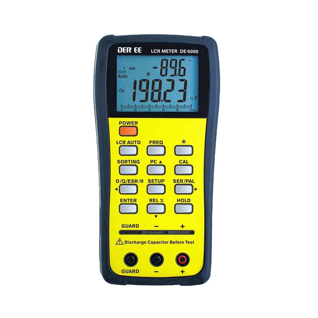
DER EE DER EE DE-5000 LCR Meter (100 kHz)
The DE-5000 is a smart, high-accurate, flexible and easy-to-use portable LCR meter. It features automatic LCR check, 4-wire Kelvin measurement, backlit display with 19999/1999 counts, multiple measurement modes and selectable test frequencies (100 Hz, 120 Hz, 1 kHz, 10 kHz or 100 kHz). The DE-5000 LCR meter is a practical helper for engineers or technicians. Features Auto L.C.R. check Ls/Lp/Cs/Cp/Rs/Rp/DCR with D/Q/θ/ESR measurement 4-wire Kelvin measurement 20,000 / 2,000 counts display Backlight Relative mode Series / Parallel modes Components sorting function Low battery indication Auto power off Specifications Test frequency 100 Hz / 120 Hz / 1 kHz / 10 kHz / 100 kHz Resistance range 20.000 Ω – 200.0 MΩ DCR range 200.00 Ω – 200.0 MΩ Capacitance range 200.00 pF – 20.00 mF Inductance range 20.000 µH – 2.000 KH Display (backlit LCD) 19999 / 1999 counts Selectable tolerance ±0.25%, ±0.5%, ±1%, ±2%, ±5%, ±10%, ±20% Power supply 9 V battery Dimensions 188 x 95 x 52 mm Weight 350 g (excluding battery) Included DE-5000 LCR meter Alligator test lead case (TL-21) AC/DC adaptor Guard line (TL-23) TL-22 SMD tweezers 9 V battery Carrying case Manual Downloads Datasheet
€ 192,39
-
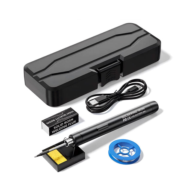
Generic Smart USB Soldering Iron Kit
The Smart USB Soldering Iron Kit is a compact, cordless solution designed for precision and portability. Featuring intelligent three-speed temperature control (300-450°C) with an easy-to-read LED display, it heats up in just 10 seconds and melts solder in as little as 6 seconds. The 1000 mAh rechargeable battery delivers up to 30 minutes of continuous use, making it ideal for quick repairs, electronics projects, and DIY tasks. With a plug-and-play, replaceable tip and a high-temperature-resistant insulated shell, it’s safe, user-friendly, and perfect for both beginners and professionals on the go. Features Three-Speed Intelligent Temperature Adjustment: Features an LED display screen with adjustable temperatures between 300-450°C (572-842°F). Easily switch between Celsius and Fahrenheit. Integrated Plug-In Soldering Iron Tip: Plug-and-play design. The tip can be replaced by simply unscrewing it, ensuring quick and convenient operation. Safe and Durable Design: High-temperature-resistant, insulated shell for enhanced safety during use. Battery Capacity: Equipped with a rechargeable 1000 mAh battery that supports up to 30 minutes of continuous operation on a full charge – ideal for everyday tasks. Efficient Performance: 8 W power with an integrated heating core for rapid heat-up. Melts tin in just 6 seconds, providing excellent thermal conductivity. Easy to Use: After powering on via USB, set your desired temperature. The soldering iron heats up in 10 seconds. Once finished, place the tip on the stand—it cools down within 1 minute. Perfect for beginners, hobbyists, basic home repairs, and training engineers. Cordless Innovation: This cordless soldering kit includes a built-in rechargeable lithium-ion battery, eliminating the need for cables. Versatile use for circuit board soldering, electrical repairs, jewelry making, metal crafts, computer maintenance, and DIY projects. Specifications Adjustable Temperature: 300-450°C (572-842°F) Tin Melting Time: <15 seconds Working Voltage: 5 V Power Output: 8 W Battery Capacity: 1000 mAh Auto Sleep Function: Activates after 10 minutes of inactivity Charging Time: Approx. 90 minutes Battery Life: Up to 30 minutes continuous use Charging Interface: USB-C Main Material: Aluminum alloy Dimensions: 190 x 16 mm (7.4 x 0.6") Included 1x USB Soldering Iron 1x Soldering Tip 1x Soldering Rosin 1x Soldering Iron Holder (with Sponge) 1x USB-C Charging Cable 1x Solder Wire 1x Storage Box
€ 34,95€ 17,50Best Price
-
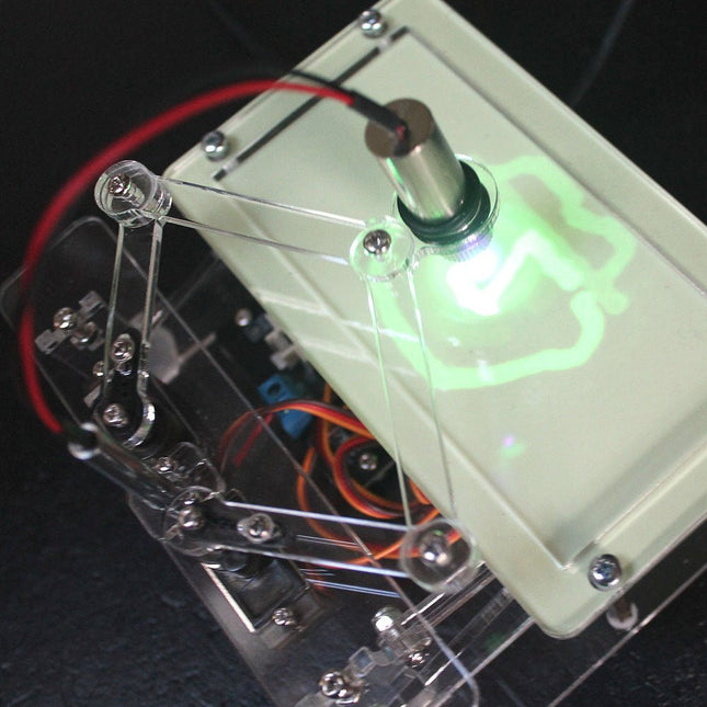
Elektor Labs Elektor Laser Head Upgrade for Sand Clock
The Elektor Laser Head transforms the Elektor Sand Clock into a clock that writes the time on glow-in-the-dark film instead of sand. In addition to displaying the time, it can also be used to create ephemeral drawings. The 5 mW laser pointer, with a wavelength of 405 nm, produces bright green drawings on the glow-in-the-dark film. For best results, use the kit in a dimly lit room. Warning: Never look directly into the laser beam! The kit includes all the necessary components, but soldering three wires is required. Note: This kit is also compatible with the original Arduino-based Sand Clock from 2017. For more details, see Elektor Magazine 1-2/2017 and Elektor Magazine 1-2/2018.
€ 34,95€ 24,95Best Price
-

Elektor Digital Wireless Power Design (E-book)
From Theory to Practical Applications in Wireless Energy Transfer and Harvesting Wireless power transmission has gained significant global interest, particularly with the rise of electric vehicles and the Internet of Things (IoT). It’s a technology that allows the transfer of electricity without physical connections, offering solutions for everything from powering small devices over short distances to long-range energy transmission for more complex systems. Wireless Power Design provides a balanced mix of theoretical knowledge and practical insights, helping you explore the potential of wireless energy transfer and harvesting technologies. The book presents a series of hands-on projects that cover various aspects of wireless power systems, each accompanied by detailed explanations and parameter listings. The following five projects guide you through key areas of wireless power: Project 1: Wireless Powering of Advanced IoT Devices Project 2: Wireless Powered Devices on the Frontline – The Future and Challenges Project 3: Wireless Powering of Devices Using Inductive Technology Project 4: Wireless Power Transmission for IoT Devices Project 5: Charging Robot Crawler Inside the Pipeline These projects explore different aspects of wireless power, from inductive charging to wireless energy transmission, offering practical solutions for real-world applications. The book includes projects that use simulation tools like CST Microwave Studio and Keysight ADS for design and analysis, with a focus on practical design considerations and real-world implementation techniques.
€ 32,95
Members: € 29,66
-

Würth Trilogy of Magnetics, 5th Edition (E-book)
Design Guide for EMI Filter Design, SMPS & RF Circuits The book focuses on the selection of components, circuitry and layout recommendations for a wide array of magnetics components, always keeping in mind an EMC point of view. Contents Basic principles The most important laws and foundations of inductive components, equivalent circuit diagrams and simulation models give the reader a basic knowledge of electronics. Components This chapter introduces inductive components and their special properties and areas of use. All relevant components are explained, from EMC components and inductors to transformers, RF components, circuit protection components, shielding materials and capacitors. Applications In this chapter, the reader will find a comprehensive overview of the principle of filter circuits, circuitry and numerous industrial applications that are explained in detail based on original examples.
€ 44,99
Members: € 40,49
-

Elektor Publishing MIT App Inventor for AI and IoT
Build Smart Applications with Raspberry Pi, Arduino, and ESP32 Discover how easy and exciting mobile app development can be with MIT App Inventor. This hands-on guide takes you from basic concepts to building real-world mobile applications using a simple visual programming approach—no prior coding experience required. You will create IoT and AI-powered apps for Android devices and explore how App Inventor can also be used with iPhones and iPads. Connect your applications to platforms such as Arduino UNO R4 WiFi, ESP32, Raspberry Pi Pico (2)W and Raspberry Pi 5, enabling you to build smart, connected systems. Inside the book, you will learn how to: Build interactive apps using buttons, images, sound, and multimedia Create text-to-speech and speech-recognition applications Develop camera-based and location-aware (GPS) apps Design useful tools such as calculators and educational apps Work with smartphone sensors like accelerometers and light sensors Build AI-powered applications, including voice assistants and image-generation features Send and receive messages, and create communication-based apps Connect mobile apps to hardware using Wi-Fi and Bluetooth Control real devices such as LEDs, motors, and sensors Designed for beginners, students, and hobbyists, this book focuses on learning by doing. By the end, you will have the skills and confidence to create your own innovative applications that interact with both the digital and physical worlds. Start building and turning your ideas into reality.
€ 44,95
Members: € 40,46
-

Elektor Digital High-End Valve Amplifiers 2 (E-book)
Nobody has any doubt that valve amplifiers produce a remarkably beautiful sound. They have a lively, deep, clear, and expressive sound, and dynamically they do not appear to have any limitations. The author investigates, in a systematic theoretical approach, the reasons for these beautiful properties. He develops new models for power valves and transformers, thus enabling the designer to determine the properties of the amplifier during the design process. Mathematical models for the coupling of power valve(s) and output transformer are provided. These will generate new insights in a special kind of distortion: the dynamic damping factor distortion (DDFD). With mathematical models in the complex domain, especially the properties at the limits of our hearing range (from 20 Hz to 20 kHz) are investigated and the minimal stability criteria for the amplifier are formulated. The often-applied negative feedback in amplifiers is extensively modelled and discussed in relation to our hearing appreciating. And after all this theory a fine selection of special amplifiers is presented and discussed. You will notice in this book that the author not only writes about amplifier technique, but tells about the way the development of valve amplifiers can have an influence on your daily life; even the usefulness of patents is discussed. Summarizing: new theories and solutions for perfect audio with valve amplifiers. Not only the professional and the DIY-er but everyone who wants to understand valve amplifiers will read this book with much pleasure.
€ 34,95
Members: € 31,46
-
Elektor Digital Object-Oriented PLC Programming in CODESYS (E-book)
Modular and Scalable Control Systems Using Structured Text This book offers a structured and practical approach to modern PLC development using object-oriented principles. It is a guide for engineers, programmers, and students seeking to harness the power of object-oriented programming (OOP) in the context of industrial automation with PLCs. The content focuses on the CODESYS development environment and Structured Text (ST), both of which support modern programming techniques while maintaining compatibility with real-time automation requirements. Through step-by-step demos and instructional examples, it demonstrates how modular, reusable code can enhance development efficiency, simplify ongoing maintenance, and enable scalable and flexible control system architectures. Key topics include: Structured Text fundamentals: conditions, loops, arrays, and functions Object-oriented concepts: classes, methods, and inheritance Advanced techniques: polymorphism, interfaces, and access control Modular design with reusable components and structured program flow Implementation of finite state machines and scalable application design Built around instructional demos and clear explanations, this book helps readers develop maintainable and modern control software in the CODESYS environment using proven programming techniques.
€ 29,95
Members: € 26,96
-
Elektor Digital Multitasking with Raspberry Pi (E-book)
Multitasking and multiprocessing have become a very important topic in microcontroller-based systems, namely in complex commercial, domestic, and industrial automation applications. As the complexity of projects grows, more functionalities are demanded from the projects. Such projects require the use of multiple inter-related tasks running on the same system and sharing the available resources, such as the CPU, memory, and input-output ports. As a result of this, the importance of multitasking operations in microcontroller-based applications has grown steadily over the last few years. Many complex automation projects now make use of some form of a multitasking kernel. This book is project-based and its main aim is to teach the basic features of multitasking using the Python 3 programming language on Raspberry Pi. Many fully tested projects are provided in the book using the multitasking modules of Python. Each project is described fully and in detail. Complete program listings are given for each project. Readers should be able to use the projects as they are, or modify them to suit their own needs. The following Python multitasking modules have been described and used in the projects: Fork Thread Threading Subprocess Multiprocessing The book includes simple multitasking projects such as independently controlling multiple LEDs, to more complex multitasking projects such as on/off temperature control, traffic lights control, 2-digit, and 4-digit 7-segment LED event counter, reaction timer, stepper motor control, keypad based projects, car park controller, and many more. The fundamental multitasking concepts such as process synchronization, process communication, and memory sharing techniques have been described in projects concerning event flags, queues, semaphores, values, and so on.
€ 32,95
Members: € 29,66
-
Elektor Digital Programming Voice-controlled IoT Applications with Alexa and Raspberry Pi (E-book)
Learn programming for Alexa devices, extend it to smart home devices and control the Raspberry Pi The book is split into two parts: the first part covers creating Alexa skills and the second part, designing Internet of Things and Smart Home devices using a Raspberry Pi. The first chapters describe the process of Alexa communication, opening an Amazon account and creating a skill for free. The operation of an Alexa skill and terminology such as utterances, intents, slots, and conversations are explained. Debugging your code, saving user data between sessions, S3 data storage and Dynamo DB database are discussed. In-skill purchasing, enabling users to buy items for your skill as well as certification and publication is outlined. Creating skills using AWS Lambda and ASK CLI is covered, along with the Visual Studio code editor and local debugging. Also covered is the process of designing skills for visual displays and interactive touch designs using Alexa Presentation Language. The second half of the book starts by creating a Raspberry Pi IoT 'thing' to control a robot from your Alexa device. This covers security issues and methods of sending and receiving MQTT messages between an Alexa device and the Raspberry Pi. Creating a smart home device is described including forming a security profile, linking with Amazon, and writing a Lambda function that gets triggered by an Alexa skill. Device discovery and on/off control is demonstrated. Next, readers discover how to control a smart home Raspberry Pi display from an Alexa skill using Simple Queue Service (SQS) messaging to switch the display on and off or change the color. A node-RED design is discussed from the basic user interface right up to configuring MQTT nodes. MQTT messages sent from a user are displayed on a Raspberry Pi. A chapter discusses sending a proactive notification such as a weather alert from a Raspberry Pi to an Alexa device. The book concludes by explaining how to create Raspberry Pi as a stand-alone Alexa device.
€ 32,95
Members: € 29,66
-
Elektor Publishing Building Wireless Sensor Networks with OpenThread
Developing CoAP applications for Thread networks with Zephyr This book will guide you through the operation of Thread, the setup of a Thread network, and the creation of your own Zephyr-based OpenThread applications to use it. You’ll acquire knowledge on: The capture of network packets on Thread networks using Wireshark and the nRF Sniffer for 802.15.4. Network simulation with the OpenThread Network Simulator. Connecting a Thread network to a non-Thread network using a Thread Border Router. The basics of Thread networking, including device roles and types, as well as the diverse types of unicast and multicast IPv6 addresses used in a Thread network. The mechanisms behind network discovery, DNS queries, NAT64, and multicast addresses. The process of joining a Thread network using network commissioning. CoAP servers and clients and their OpenThread API. Service registration and discovery. Securing CoAP messages with DTLS, using a pre-shared key or X.509 certificates. Investigating and optimizing a Thread device’s power consumption. Once you‘ve set up a Thread network with some devices and tried connecting and disconnecting them, you’ll have gained a good insight into the functionality of a Thread network, including its self-healing capabilities. After you’ve experimented with all code examples in this book, you’ll also have gained useful programming experience using the OpenThread API and CoAP.
€ 39,95
Members: € 35,96
-
Elektor Digital Elektor Circuit Special 2023 PDF (EN)
Elektor GREEN and GOLD members can download their digital edition here. Not a member yet? Click here. Tiny Solar SupplySunlight In, 3.3 V Out Solid-State Stereo Audio SwitchFree of Clicks and Moving Parts Large RGB DigitWith Through-Hole WS2812 LEDs Microphone Preamplifier with 48-V Phantom Power DistributionGreat for Podcasting and Pro Audio Square Wave Generators with Duty Cycle and Frequency ControlsSimple Circuits with CMOS and TTL ICs Simple Dynamic CompressorWith Soft Control and Warm Sound Simple Electronic Lock Active RectifierA solution or 2…40 V at up to 3 A with Reverse Current Suppression On / Off Switching System for Active Boxes Unbalanced/Balanced ConverterWith RFI Filter and DC Protection 2023: An AI OdysseyWhere Did It Come From? Where Is It Going? Speed Controller for Fan or VentilatorWith Manual and Thermostat Modes The Latest from Arduino Project HubNew Projects from the Community Power Overload MonitorMonitor Power Lines for Excessive Current Blink in the Dark Without TransistorsAn Oscillator with Only Two-Terminal Parts Morse Code GeneratorUse It as Beacon or Learning Device! Programmable Video DACHandles Any Format up to RGB888 A T(eeny) Tiny PianoWithout Moving Parts Dual Dice without MCUDual Dice on a Single PCB – Plus Some Design Tricks Electronic Scarecrow Circuits to Amuse, Inspire, and Amaze LC-LP-HA ThermometerAccurate Measurements and a Binary Display THD GeneratorGenerating Distortion on Purpose Thyristor-Based Overtemperature IndicatorElectronic Components Used Unconventionally PTC Fuse Flip-Flop Funny BirdA Chirping Elektor Classic Neon Lamp with a Microcontroller Temperature-Stabilized IC Current SourceNeutralizing the Temperature Drift of Integrated Current Sources Second-Order Adjustable Treble BoostA Special Hearing Aid for the Elderly Edwin Comes HomeA Look Back After 53 Years One-Armed BanditA Simple, Fun, Nostalgic, and Educational Elektor Classic! Simple Digitally Controlled Variable Resistor Water Leak ProtectionSafeguard and Alarm for Water Leaks Eco-Timer with Auto-ShutdownNeeds 0.0 mW in Off Mode! ChatGPT and Arduino ZD MeterMeasuring Z Voltages of Z Diodes ≤ 100 V Servo Tester ESP32 Windows Controller with Free Software Analog and Mixed-Signal ICs by MicrochipLow-Consumption Power Management and Signal Processing Interface StandardsFilter and Surge Protection for the I²C Bus Li-Ion Battery MonitorResidual Charge Indicator Provides Visual Feedback PS/2 Mouse As Rotary Encoder (and More…) Simple Twilight Switchfor Retrofitting Lamps or Installations Water Pump ControllerPrepare Yourself Against Rising Water Levels Solar-Powered Christmas FM Radio BallAll You Want for Christmas Is This Vibration Sensor with RelayTap or Shake to Switch On Continuity TesterSensitive and Unintrusive Power On/Off with a Pushbutton Mini-Drill Power Control 2023A Revision of a Design from 1980 Digital Vibration SensorTurn Vibrations into Precisely Timed Pulses Reverse-Polarity Protection with Low Voltage Drop A Low-Cost Frequency Standard Tiny DCF77 SimulatorAn Accurate Fake-Time Standard The Lilygo T-PicoC3Combines RP2040 and ESP32-C3 with Full Color-TFT Display
€ 7,50
-

Zhongdi ZD-8962B ESD Soldering Station (70 W)
The ZD-8962B soldering station features an adjustable temperature range of 160°C to 480°C with an output power of 70 W. Equipped with an integrated heating element in the soldering tip, the station reaches the desired operating temperature in just 8 seconds. A large digital display provides real-time monitoring, showing both the preset target and the actual temperature of the iron for precision control. Additionally, the station is ESD-safe, ensuring sensitive electronic components are fully protected from electrostatic discharge during use. Specifications Power 70 W Input voltage 220-240 V AC/50 Hz Output voltage 20 V Temperature range 160°C – 480°C (320°F – 896°F) Heating time ~8 s Display Large, two-line LED display for showing target and actual temperature Special features ESD protection, Sleep mode/energy-saving function, Switch between °C and °F Included ZD-8962B Soldering station unit Soldering iron Soldering tip N12-1 Soldering iron stand with copper brush and sponge Soldering wire stand with lead-free soldering wire (10 g) Power cable (EU) Manual
€ 69,95€ 59,95Best Price
-
Elektor Digital Elektor Espressif Guest Edition (PDF)
Elektor GREEN and GOLD members can download their digital edition here. Not a member yet? Click here. Accelerating IoT Innovation A Color E-Ink Wi-Fi Picture Frame ESP-Launchpad TutorialFrom Zero to Flashing in Minutes ESP32 and ChatGPTOn the Way to a Self-Programming System… Walkie-Talkie with ESP-NOWNot Quite Wi-Fi, Not Quite Bluetooth! From Idea to Circuit with the ESP32-S3A Guide to Prototyping with Espressif Chips AIoT Chip InnovationAn Interview With Espressif CEO Teo Swee-Ann Simulate ESP32 with WokwiYour Project’s Virtual Twin Trying Out the ESP32-S3-BOX-3A Comprehensive AIoT Development Platform Electronics Workspace EssentialsInsights and Tips From Espressif Engineers The ESP RainMaker StoryHow We Built “Your” IoT Cloud Assembling the Elektor Cloc 2.0 KitAn Elektor Product Unboxed by Espressif Unleashing the ESP32-P4The Next Era of Microcontrollers Rust + EmbeddedA Development Power Duo Who Are the Rust-Dacious Embedded Developers?How Espressif is Cultivating Embedded Rust for the ESP32 Espressif’s Series of SoCs Building a PLC with Espressif SolutionsWith the Capabilities and Functionality of the ISOBUS Protocol The ESP32-S3 VGA BoardBitluni’s Exciting Journey Into Product Design Acoustic Fingerprinting on ESP32Song Recognition With Open-Source Project Olaf Circular Christmas Tree 2023A High-Tech Way to Celebrate the Holiday Season A Simpler and More Convenient LifeAn Amateur Project Based on the Espressif ESP8266 Module How to Build IoT Apps without Software ExpertiseWith Blynk IoT Platform and Espressif Hardware Building a Smart User Interface on ESP32 Quick & Easy IoT Development with M5Stack Prototyping an ESP32-Based Energy Meter A Value-Added Distributor for IoT and More In-Depth Insights: Interview With Arduino on the Nano ESP32Alessandro Ranellucci and Martino Facchin Discuss Espressif Collaboration Your AIoT Solution ProviderInsights From Espressif Streamlining MCU Development With ESP-IDF Privilege Separation An Open-Source Speech Recognition Server……and the ESP BOX The Thinking EyeFacial Recognition and More Using the ESP32-S3-EYE ESP32-C2-Based Coin Cell SwitchDesign and Performance Evaluation The Smart Home Leaps Forward with MatterUnlocking Smart Home IoT Potential Tech the Future: Where Is Smart Home IoT Headed?
€ 7,50
-

Elektor Publishing Edge AI Made Practical
AI Projects for the Raspberry Pi with the AI HAT+ Edge AI is transforming everyday devices by putting intelligence where it matters most: directly inside the hardware. With on-device inference, a camera can recognize a visitor instantly, a phone can translate speech without streaming audio to the cloud, and a wearable can detect anomalies in real time—fast, private, and reliable even when the network disappears. This book is your practical guide to building exactly those kinds of systems with the Raspberry Pi AI HAT+ and the Hailo-8L accelerator. You’ll start with clear foundations: core AI and machine-learning concepts, how neural networks work, and what truly distinguishes Edge AI from cloud AI—plus an honest look at ethical considerations and future impacts. Then it’s straight to hands-on physical computing. Step by step, you’ll set up Raspberry Pi OS, power and cooling, and develop in Python using the Thonny IDE. You’ll learn GPIO basics with lights and servos, mount the AI HAT+ hardware, install and verify the Hailo software stack, and connect the right camera—official modules or USB webcams, even multiple cameras. From your first pipeline to real projects, you’ll run person detection, pose estimation, segmentation, and depth estimation, then level up with YOLO object detection: smart alerts, guest counters, and custom extensions. You’ll even connect vision to motion by combining gesture recognition with servo-driven mechanisms, including a robotic arm. With troubleshooting tips, hardware essentials, and a practical Python refresher, this book turns Edge AI from buzzword into buildable reality.
€ 34,95€ 29,95Best Price


