Products
-
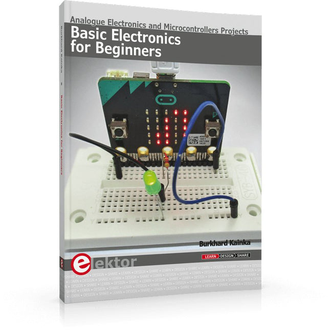
Elektor Publishing Basic Electronics for Beginners
Analogue Electronics and Microcontrollers Projects Hobbyist electronics can be a fun way to learn new skills that can be helpful to your career. Those who understand the basics of electronics can design their own circuits and projects. However, before you run, you need to learn to walk. It all starts with analogue electronics. You should be familiar with the simple components and circuits and understand their basic behaviors and the issues you may encounter. The best way to do this is through real experiments. Theory alone is not enough. This book offers a large number of practical entry-level circuits, with which everyone can gain the basic experience. Through the widespread introduction of microcontrollers, a new chapter in electronics has begun. Microcontrollers are now performing more and more tasks that were originally solved using discrete components and conventional ICs. Starting out has become easier and easier thanks to platforms including Bascom, Arduino, micro:bit. The book introduces numerous manageable microcontroller applications. It’s now a case of less soldering and more programming.
€ 39,95
Members € 35,96
-

Elektor Digital Basic Electronics for Beginners (E-book)
Analogue Electronics and Microcontrollers Projects Hobbyist electronics can be a fun way to learn new skills that can be helpful to your career. Those who understand the basics of electronics can design their own circuits and projects. However, before you run, you need to learn to walk. It all starts with analogue electronics. You should be familiar with the simple components and circuits and understand their basic behaviors and the issues you may encounter. The best way to do this is through real experiments. Theory alone is not enough. This book offers a large number of practical entry-level circuits, with which everyone can gain the basic experience. Through the widespread introduction of microcontrollers, a new chapter in electronics has begun. Microcontrollers are now performing more and more tasks that were originally solved using discrete components and conventional ICs. Starting out has become easier and easier thanks to platforms including Bascom, Arduino, micro:bit. The book introduces numerous manageable microcontroller applications. It?s now a case of less soldering and more programming.
€ 32,95
Members € 26,36
-
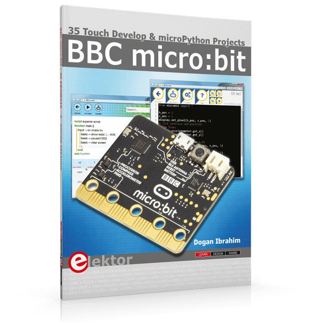
Elektor Publishing BBC micro:bit (Book)
35 Touch Develop & MicroPython Projects The BBC micro:bit is a credit sized computer based on a highly popular and high performance ARM processor. The device is designed by a group of 29 partners for use in computer education in the UK and will be given free of charge to every secondary school student in the UK. The device is based on the Cortex-M0 processor and it measures 4 x 5 cm. It includes several important sensors and modules such as an accelerometer, magnetometer, 25 LEDs, 2 programmable push-button switches, Bluetooth connectivity, micro USB socket, 5 ring type connectors, and a 23-pin edge connector. The device can be powered from its micro USB port by connecting it to a PC, or two external AAA type batteries can be used. This book is about the use of the BBC micro:bit computer in practical projects. The BBC micro:bit computer can be programmed using several different programming languages, such as Microsoft Block Editor, Microsoft Touch Develop, MicroPython, and JavaScript. The book makes a brief introduction to the Touch Develop programming language and the MicroPython programming language. It then gives 35 example working and tested projects using these language. Readers who learn to program in Touch Develop and MicroPython should find it very easy to program using the Block Editor or any other languages. The following are given for each project: Title of the project Description of the project Aim of the project Touch Develop and MicroPython program listings Complete program listings are given for each project. In addition, working principles of the projects are described briefly in each section. Readers are encouraged to go through the projects in the order given in the book.
€ 29,95€ 11,98
Members identical
-

Elektor Digital BBC micro:bit (E-book)
35 Touch Develop & MicroPython Projects The BBC micro:bit is a credit sized computer based on a highly popular and high performance ARM processor. The device is designed by a group of 29 partners for use in computer education in the UK and will be given free of charge to every secondary school student in the UK. The device is based on the Cortex-M0 processor and it measures 4 x 5 cm. It includes several important sensors and modules such as an accelerometer, magnetometer, 25 LEDs, 2 programmable push-button switches, Bluetooth connectivity, micro USB socket, 5 ring type connectors, and a 23-pin edge connector. The device can be powered from its micro USB port by connecting it to a PC, or two external AAA type batteries can be used. This book is about the use of the BBC micro:bit computer in practical projects. The BBC micro:bit computer can be programmed using several different programming languages, such as Microsoft Block Editor, Microsoft Touch Develop, MicroPython, and JavaScript. The book makes a brief introduction to the Touch Develop programming language and the MicroPython programming language. It then gives 35 example working and tested projects using these language. Readers who learn to program in Touch Develop and MicroPython should find it very easy to program using the Block Editor or any other languages. The following are given for each project: Title of the project Description of the project Aim of the project Touch Develop and MicroPython program listings Complete program listings are given for each project. In addition, working principles of the projects are described briefly in each section. Readers are encouraged to go through the projects in the order given in the book.
€ 24,95
Members € 19,96
-

Elektor Digital Build Your Own Multifunctional 4-Axis CNC Machine (E-book)
Plot, Cut, Drill, Mill and Laser with the Z99 This book covers the construction, hardware, software, and operation of the Z99 – CNC machine. This is a multifunctional 4-axis machine for home construction. The capabilities of the Z99 machine include: large-format schematic plotting PCB plotting with etch-resist pens schematic plotting with conductive-ink pens letter cutting out of vinyl paper cutting PCB/substrate drilling PCB/substrate milling text milling laser engraving laser cutting of solder paste masks By making the support software available as freeware, readers of the book are challenged and encouraged to develop new applications for the Z99. The machine would not be of much use if the user has no option to create suitable files for the designs in mind. A large part of this book is dedicated to creating source files in a variety of freeware software packages, including Inkscape, DesignSpark PCB, KiCad, and FlatCAM. The book is also useful for readers keen to comprehend and then master the basic structure of HPGL, Gerber, Drill, and G-code files, as well as to have a go at deciphering them using software.
€ 29,95
Members € 23,96
-
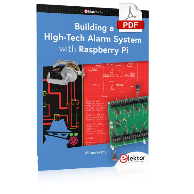
Elektor Digital Building a High-Tech Alarm System with Raspberry Pi (E-book)
This book discusses the basic components of any alarm system. All alarm systems have two basic functions. First, they monitor their environment looking for a change such as a door or window opening or someone moving about in the room. Second, they alert the legal owner or user to this change. The system described in this book uses a scanning type software to detect intruders. It behaves like a guard dog, pacing up and down the fence line on the lookout for either an intruder or a familiar person. If you have an alarm key, you can disarm the system and enter. With the scanning method, the software is easy to write and explain. It can scan eight alarm zones plus two special fire zones in about one second. You don’t have to be an electrical engineer to install an alarm system, just a decent carpenter, painter, and plasterer! Because this alarm system runs on 12 volts, you don’t have to be a licensed electrician either to install it. The alarm system presented here uses Python software on the Raspberry Pi combined with some elementary electronic circuits. The code described in the book, as well as CAD files and a bill of materials for the alarm panel, are available for free downloading. The book provides the reader with examples of typical configurations coming straight from the author‘s experience. After reviewing the hardware components typically used in common alarm systems, the author shows how to plan one yourself. To implement a modular alarm, no matter if it is for a single house or for a business or restaurant, the book shows how to skillfully combine a Raspberry Pi with small auxiliary electronic circuits. These are not installation instructions but food for thought that will enable readers to find a solution to their needs.
€ 24,95
Members € 19,96
-
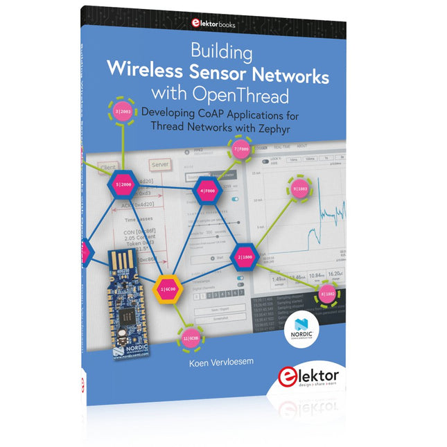
Elektor Publishing Building Wireless Sensor Networks with OpenThread
Developing CoAP applications for Thread networks with Zephyr This book will guide you through the operation of Thread, the setup of a Thread network, and the creation of your own Zephyr-based OpenThread applications to use it. You’ll acquire knowledge on: The capture of network packets on Thread networks using Wireshark and the nRF Sniffer for 802.15.4. Network simulation with the OpenThread Network Simulator. Connecting a Thread network to a non-Thread network using a Thread Border Router. The basics of Thread networking, including device roles and types, as well as the diverse types of unicast and multicast IPv6 addresses used in a Thread network. The mechanisms behind network discovery, DNS queries, NAT64, and multicast addresses. The process of joining a Thread network using network commissioning. CoAP servers and clients and their OpenThread API. Service registration and discovery. Securing CoAP messages with DTLS, using a pre-shared key or X.509 certificates. Investigating and optimizing a Thread device’s power consumption. Once you‘ve set up a Thread network with some devices and tried connecting and disconnecting them, you’ll have gained a good insight into the functionality of a Thread network, including its self-healing capabilities. After you’ve experimented with all code examples in this book, you’ll also have gained useful programming experience using the OpenThread API and CoAP.
€ 39,95
Members € 35,96
-

Elektor Digital Building Wireless Sensor Networks with OpenThread (E-book)
Developing CoAP applications for Thread networks with Zephyr This book will guide you through the operation of Thread, the setup of a Thread network, and the creation of your own Zephyr-based OpenThread applications to use it. You’ll acquire knowledge on: The capture of network packets on Thread networks using Wireshark and the nRF Sniffer for 802.15.4. Network simulation with the OpenThread Network Simulator. Connecting a Thread network to a non-Thread network using a Thread Border Router. The basics of Thread networking, including device roles and types, as well as the diverse types of unicast and multicast IPv6 addresses used in a Thread network. The mechanisms behind network discovery, DNS queries, NAT64, and multicast addresses. The process of joining a Thread network using network commissioning. CoAP servers and clients and their OpenThread API. Service registration and discovery. Securing CoAP messages with DTLS, using a pre-shared key or X.509 certificates. Investigating and optimizing a Thread device’s power consumption. Once you‘ve set up a Thread network with some devices and tried connecting and disconnecting them, you’ll have gained a good insight into the functionality of a Thread network, including its self-healing capabilities. After you’ve experimented with all code examples in this book, you’ll also have gained useful programming experience using the OpenThread API and CoAP.
€ 32,95
Members € 26,36
-
Raspberry Pi Foundation Bumper for Raspberry Pi 5
The Raspberry Pi Bumper is a snap-on silicone cover that protects the bottom and edges of the Raspberry Pi 5. Features One-piece flexible silicone rubber bumper Enables easy access to the power button Mounting holes remain accessible underneath the bumper Downloads Datasheet
€ 3,50€ 1,40
Members identical
-
Elektor Digital C Programming for Embedded Microcontrollers (E-book)
Technology is constantly changing. New microcontrollers become available every year and old ones become redundant. The one thing that has stayed the same is the C programming language used to program these microcontrollers. If you would like to learn this standard language to program microcontrollers, then this book is for you! ARM microcontrollers are available from a large number of manufacturers. They are 32-bit microcontrollers and usually contain a decent amount of memory and a large number of on-chip peripherals. Although this book concentrates on ARM microcontrollers from Atmel, the C programming language applies equally to other manufacturer’s ARMs as well as other microcontrollers. Features of this book Use only free or open source software. Learn how to download, set up and use free C programming tools. Start learning the C language to write simple PC programs before tackling embedded programming - no need to buy an embedded system right away! Start learning to program from the very first chapter with simple programs and slowly build from there. No programming experience is necessary! Learn by doing - type and run the example programs and exercises. Sample programs and exercises can be downloaded from the Internet. A fun way to learn the C programming language. Ideal for electronic hobbyists, students and engineers wanting to learn the C programming language in an embedded environment on ARM microcontrollers.
€ 29,95
Members € 23,96
-
Elektor Digital C Programming on Raspberry Pi (E-book)
Develop innovative hardware-based projects in C The Raspberry Pi has traditionally been programmed using Python. Although this is a very powerful language, many programmers may not be familiar with it. C on the other hand is perhaps the most commonly used programming language and all embedded microcontrollers can be programmed using it. The C language is taught in most technical colleges and universities and almost all engineering students are familiar with using it with their projects. This book is about using the Raspberry Pi with C to develop a range of hardware-based projects. Two of the most popular C libraries, wiringPi and pigpio are used. The book starts with an introduction to C and most students and newcomers will find this chapter invaluable. Many projects are provided in the book, including using Wi-Fi and Bluetooth to establish communication with smartphones. Many sensor and hardware-based projects are included. Both wiringPi and pigpio libraries are used in all projects. Complete program listings are given with full explanations. All projects have been fully tested and work. The following hardware-based projects are provided in the book: Using sensors Using LCDs I²C and SPI buses Serial communication Multitasking External and timer interrupts Using Wi-Fi Webservers Communicating with smartphones Using Bluetooth Sending data to the cloud Program listings of all Raspberry Pi projects developed in this book are available on the Elektor website. Readers can download and use these programs in their projects. Alternatively, they can customize them to suit their applications.
€ 32,95
Members € 26,36
-
Elektor Digital C Programming with Arduino (E-book)
Technology is constantly changing. New microcontrollers become available every year. The one thing that has stayed the same is the C programming language used to program these microcontrollers. If you would like to learn this standard language to program microcontrollers, then this book is for you! Arduino is the hardware platform used to teach the C programming language as Arduino boards are available worldwide and contain the popular AVR microcontrollers from Atmel. Atmel Studio is used as the development environment for writing C programs for AVR microcontrollers. It is a full-featured integrated development environment (IDE) that uses the GCC C software tools for AVR microcontrollers and is free to download. At a glance: Start learning to program from the very first chapter No programming experience is necessary Learn by doing – type and run the example programs A fun way to learn the C programming language Ideal for electronic hobbyists, students and engineers wanting to learn the C programming language in an embedded environment on AVR microcontrollers Use the free full-featured Atmel Studio IDE software for Windows Write C programs for 8-bit AVR microcontrollers as found on the Arduino Uno and MEGA boards Example code runs on Arduino Uno and Arduino MEGA 2560 boards and can be adapted to run on other AVR microcontrollers or boards Use the AVR Dragon programmer/debugger in conjunction with Atmel Studio to debug C programs
€ 39,95
Members € 31,96
-

Elektor Digital C# Programming for Windows and Android (E-book)
This e-book (pdf), a software-only follow up to the best-selling Elektor Visual Studio C# range of books, is aimed at Engineers, Scientists and Enthusiasts who want to learn about the C# language and development environment. It covers steps from installation, the .NET framework and object oriented programming, through to more advanced concepts including database applications, threading and multi-tasking, internet/network communications and writing DLLs. The DirectX chapters also include video capture. The e-book concludes with several chapters on writing Android applications in C# using the Xamarin add-on. This e-book is based on the Visual Studio 2015 development environment and latest C# additions including WPF applications, LINQ queries, Charts and new commands such as await and async. The latest Visual Studio debugging features (PerfTips, Diagnostic Tool window and IntellTrace) are covered. Finally, the Android chapters include GPS, E-mail and SMS applications. Additionally, the e-book provides free on-line access to extensive, well-documented examples — in a try for yourself style — together with links to the author’s videos, guiding you through the necessary steps to get the expected results.
€ 39,95
Members € 31,96
-
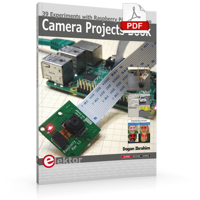
Elektor Digital Camera Projects Book (E-book)
39 Experiments with Raspberry Pi and Arduino This book is about Raspberry Pi 3 and Arduino camera projects. The book explains in simple terms and with tested and working example projects, how to configure and use a Raspberry Pi camera and USB based webcam in camera-based projects using a Raspberry Pi. Example projects are given to capture images, create timelapse photography, record video, use the camera and Raspberry Pi in security and surveillance applications, post images to Twitter, record wildlife, stream live video to YouTube, use a night camera, send pictures to smartphones, face and eye detection, colour and shape recognition, number plate recognition, barcode recognition and many more. Installation and use of popular image processing libraries and software including OpenCV, SimpleCV, and OpenALPR are explained in detail using a Raspberry Pi. The book also explains in detail how to use a camera on an Arduino development board to capture images and then save them on a microSD card. All projects given in this book have been fully tested and are working. Program listings for all Raspberry Pi and Arduino projects used in this book are available for download on the Elektor website.
€ 29,95
Members € 23,96
-
JOY-iT Case for 7" RGB-Touch-Display for Raspberry Pi
Case for 7' RGB-Touch-Display for Raspberry Pi
€ 12,95€ 5,18
Members identical
-
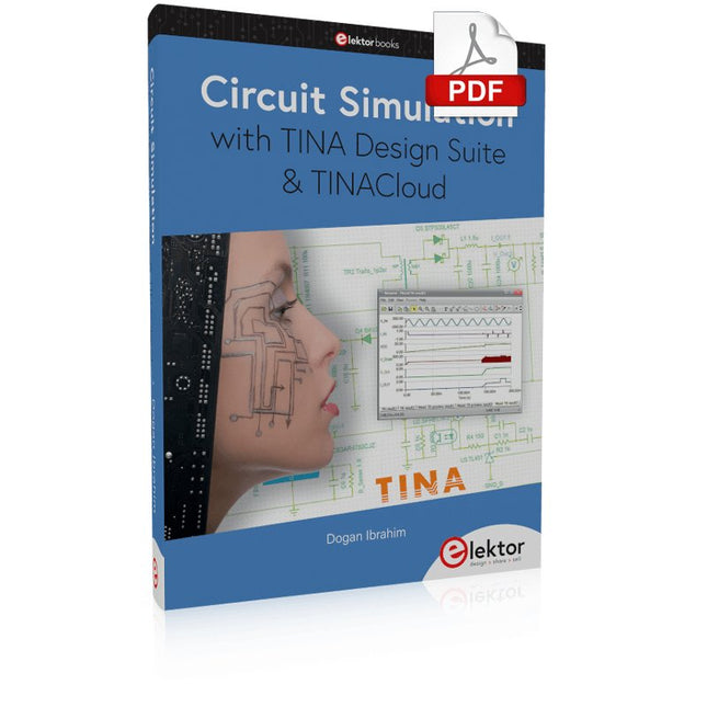
Elektor Digital Circuit Simulation with TINA Design Suite & TINACloud (E-book)
TINA Design Suite is a professional, powerful and affordable circuit simulator. It is a circuit designer and PCB design software package for analysing, designing, and real-time testing of analogue, digital, IBIS, VHDL, Verilog, Verilog AMS, SystemC, MCU, and mixed electronic circuits and their PCB layouts. In this book, top-selling Elektor author, Prof. Dr. Dogan Ibrahim aims to teach the design and analysis of electrical and electronic circuits and develop PCB boards using both TINA and TINACloud. The book is aimed at electrical/electronic engineers, undergraduate electronic/electrical engineering students at technical colleges and universities, postgraduate and research students, teachers, and hobbyists. Many tested and working simulation examples are provided covering most fields of analogue and digital electrical/electronic engineering. These include AC and DC circuits, diodes, zener diodes, transistor circuits, operational amplifiers, ladder diagrams, 3-phase circuits, mutual inductance, rectifier circuits, oscillators, active and passive filter circuits, digital logic, VHDL, MCUs, switch-mode power supplies, PCB design, Fourier series, and spectrum. Readers do not need to have any programming experience unless they wish to simulate complex MCU circuits.
€ 39,95
Members € 31,96
-
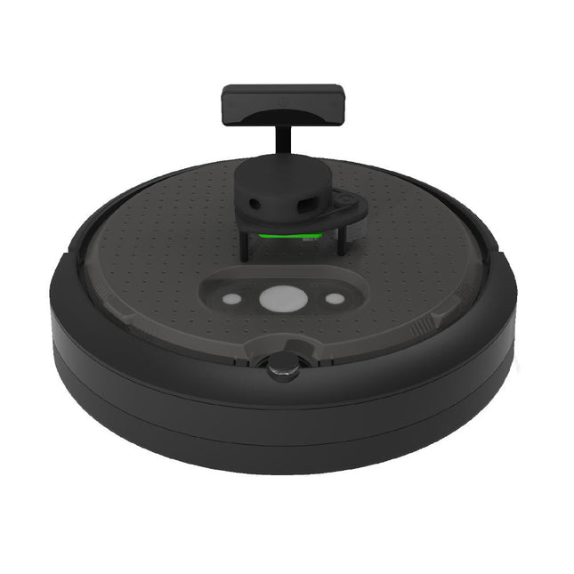
Clearpath Robotics Clearpath Robotics TurtleBot 4 Lite
TurtleBot 4 is the next-generation of the world’s most popular open source robotics platform for education and research, offering better computing power, better sensors and a world class user experience at an affordable price point.TurtleBot 4 Lite is equipped with an iRobot Create 3 mobile base, a powerful Raspberry Pi 4 running ROS 2, OAK-D spatial AI stereo camera, 2D LiDAR and more. All components have been seamlessly integrated to deliver an out-of-the-box development and learning platform.Specifications Base platform iRobot Create 3 Wheels (Diameter) 72 mm Ground Clearance 4.5 mm On-board Computer Raspberry Pi 4 (4 GB) Maximum linear velocity 0.31 m/s in safe mode0.46 m/s without safe mode Maximum angular velocity 1.90 rad/s Maximum payload 9 kg Operation time 2h 30m – 4h depending on load Charging time 2h 30m Lidar RPLIDAR A1M8 Camera OAK-D-Lite User Power VBAT @1.9 A5 V @ Low current3.3 V @ Low current USB Expansion 2x USB 2.0 (Type A)2x USB 3.0 (Type A) Programmable LEDs Create 3 Lightring Buttons and Switches 2x Create 3 User buttons1x Create 3 Power Button Battery 26 Wh Lithium Ion (14.4 V nominal) Charging Dock Included Size (L x W x H) 342 x 339 x 192 mm Weight 3.3 kg DownloadsUser Manual
€ 1.699,00
Members identical
-
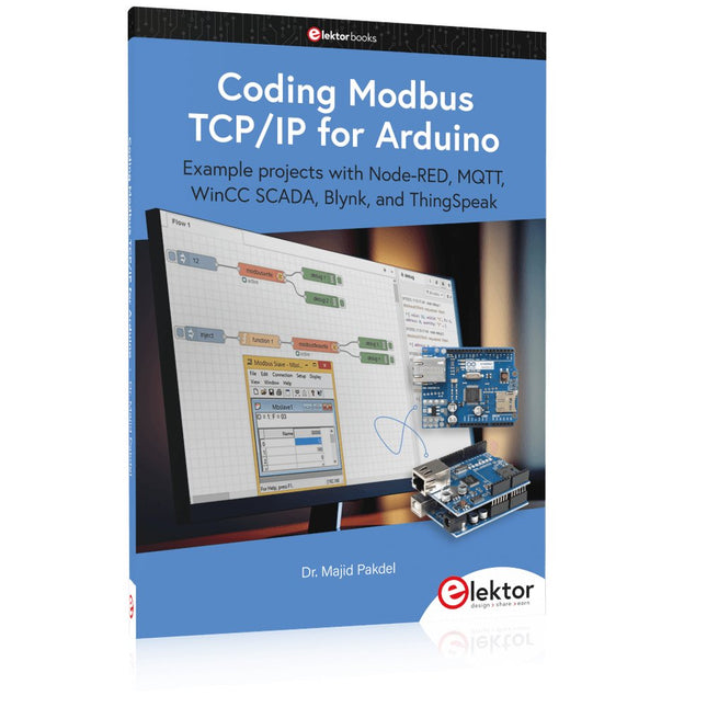
Elektor Publishing Coding Modbus TCP/IP for Arduino
Example projects with Node-RED, MQTT, WinCC SCADA, Blynk, and ThingSpeak This comprehensive guide unlocks the power of Modbus TCP/IP communication with Arduino. From the basics of the Modbus protocol right up to full implementation in Arduino projects, the book walks you through the complete process with lucid explanations and practical examples. Learn how to set up Modbus TCP/IP communication with Arduino for seamless data exchange between devices over a network. Explore different Modbus functions and master reading and writing registers to control your devices remotely. Create Modbus client and server applications to integrate into your Arduino projects, boosting their connectivity and automation level. With detailed code snippets and illustrations, this guide is perfect for beginners and experienced Arduino enthusiasts alike. Whether you‘re a hobbyist looking to expand your skills or a professional seeking to implement Modbus TCP/IP communication in your projects, this book provides all the knowledge you need to harness the full potential of Modbus with Arduino. Projects covered in the book: TCP/IP communication between two Arduino Uno boards Modbus TCP/IP communication within the Node-RED environment Combining Arduino, Node-RED, and Blynk IoT cloud Interfacing Modbus TCP/IP with WinCC SCADA to control sensors Using MQTT protocol with Ethernet/ESP8266 Connecting to ThingSpeak IoT cloud using Ethernet/ESP8266
€ 39,95
Members identical
-

Elektor Digital Coding Modbus TCP/IP for Arduino (E-book)
Example projects with Node-RED, MQTT, WinCC SCADA, Blynk, and ThingSpeak This comprehensive guide unlocks the power of Modbus TCP/IP communication with Arduino. From the basics of the Modbus protocol right up to full implementation in Arduino projects, the book walks you through the complete process with lucid explanations and practical examples. Learn how to set up Modbus TCP/IP communication with Arduino for seamless data exchange between devices over a network. Explore different Modbus functions and master reading and writing registers to control your devices remotely. Create Modbus client and server applications to integrate into your Arduino projects, boosting their connectivity and automation level. With detailed code snippets and illustrations, this guide is perfect for beginners and experienced Arduino enthusiasts alike. Whether you‘re a hobbyist looking to expand your skills or a professional seeking to implement Modbus TCP/IP communication in your projects, this book provides all the knowledge you need to harness the full potential of Modbus with Arduino. Projects covered in the book: TCP/IP communication between two Arduino Uno boards Modbus TCP/IP communication within the Node-RED environment Combining Arduino, Node-RED, and Blynk IoT cloud Interfacing Modbus TCP/IP with WinCC SCADA to control sensors Using MQTT protocol with Ethernet/ESP8266 Connecting to ThingSpeak IoT cloud using Ethernet/ESP8266
€ 32,95
Members € 26,36
-
Elektor Digital Computer Vision (EN) PDF
Computer vision is probably the most exciting branch of image processing, and the number of applications in robotics, automation technology and quality control is constantly increasing. Unfortunately entering this research area is, as yet, not simple. Those who are interested must first go through a lot of books, publications and software libraries. With this book, however, the first step is easy. The theoretically founded content is understandable and is supplemented by many practical examples. Source code is provided with the specially developed platform-independent open source library IVT in the programming language C/C++. The use of the IVT is not necessary, but it does make for a much easier entry and allows first developments to be quickly produced. The authorship is made up of research assistants of the chair of Professor Ruediger Dillmann at the Institut für Technische Informatik (ITEC), Universitaet Karlsruhe (TH). Having gained extensive experience in image processing in many research and industrial projects, they are now passing this knowledge on. Among other subjects, the following are dealt with in the fundamentals section of the book: Lighting, optics, camera technology, transfer standards, camera calibration, image enhancement, segmentation, filters, correlation and stereo vision. The practical section provides the efficient implementation of the algorithms, followed by many interesting applications such as interior surveillance, bar code scanning, object recognition, 3-D scanning, 3-D tracking, a stereo camera system and much more.
€ 19,95
Members € 15,96
-
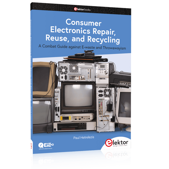
Elektor Publishing Consumer Electronics Repair, Reuse and Recycling
A Combat Guide against E-waste and Throwawayism This book is for anyone who enjoys tinkering with analog and digital hardware electronics. Regardless of the sophistication of your workspace, only basic tools are required to achieve truly satisfying results. It is intended as a reference guide among other hardware repair publications you may have in your library. However, the book goes a step further than most other repair guides in addressing issues in the modern era of discarded electronics called e-waste. E-waste should be put to good use. Producing anything new requires not just precious resources and labor, but also energy to make and deliver it to global retail shelves. Your talents and love of electronics can be put to good use by rescuing and resurrecting at least selected units from this endless stream of e-waste. Examples include either restoring through repair, or salvaging reusable electronic and mechanical components for your next project. Smart tips are provided throughout the book, and much information is tabulated for easy reference. The book expands age-old repair and hacking techniques applied for repair on the workbench into clever methods and applications to achieve effective results with discarded or “non-servicable” electronic consumer products. The final chapter provides real-life examples using all of the previously discussed content in a summarized form for each example repair type.
€ 39,95
Members € 35,96
-

Elektor Digital Consumer Electronics Repair, Reuse and Recycling (E-book)
A Combat Guide against E-waste and Throwawayism This book is for anyone who enjoys tinkering with analog and digital hardware electronics. Regardless of the sophistication of your workspace, only basic tools are required to achieve truly satisfying results. It is intended as a reference guide among other hardware repair publications you may have in your library. However, the book goes a step further than most other repair guides in addressing issues in the modern era of discarded electronics called e-waste. E-waste should be put to good use. Producing anything new requires not just precious resources and labor, but also energy to make and deliver it to global retail shelves. Your talents and love of electronics can be put to good use by rescuing and resurrecting at least selected units from this endless stream of e-waste. Examples include either restoring through repair, or salvaging reusable electronic and mechanical components for your next project. Smart tips are provided throughout the book, and much information is tabulated for easy reference. The book expands age-old repair and hacking techniques applied for repair on the workbench into clever methods and applications to achieve effective results with discarded or “non-servicable” electronic consumer products. The final chapter provides real-life examples using all of the previously discussed content in a summarized form for each example repair type.
€ 32,95
Members € 26,36
-

Elektor Publishing Control Engineering with Fuzzy Logic
Practical Applications and Project with Arduino, ESP32, and RP2040 Immerse yourself in the fascinating world of control engineering with Arduino and ESP32! This book offers you a practical introduction to classic and modern control methods, including PID controllers, fuzzy logic, and sliding-mode controllers. In the first part, you will learn the basics of the popular Arduino controllers, such as the Arduino Uno and the ESP32, as well as the integration of sensors for temperature and pH measurement (NTC, PT100, PT1000, and pH sensor). You will learn how to use these sensors in various projects and how to visualize data on a Nextion TFT display. The course continues with an introduction to actuators such as MOSFET switches, H-bridges, and solid-state relays, which are used to control motors and actuators. You will learn to analyze and model controlled systems, including PT1 and PT2 control. The book focuses on the implementation of fuzzy and PID controllers for controlling temperature and DC motors. Both the Arduino Uno and the ESP32 are used. The sliding-mode controller is also introduced. In the second-to-last chapter, you will explore the basics of neural networks and learn how machine learning can be used on an Arduino. In the last chapter, there is a practical example of a fuzzy controller for feeding electricity into the household grid. This book is the perfect choice for engineers, students, and electronics engineers who want to expand their projects with innovative control techniques.
€ 44,95
Members € 40,46
-

Elektor Digital Control Engineering with Fuzzy Logic (E-book)
Practical Applications and Project with Arduino, ESP32, and RP2040 Immerse yourself in the fascinating world of control engineering with Arduino and ESP32! This book offers you a practical introduction to classic and modern control methods, including PID controllers, fuzzy logic, and sliding-mode controllers. In the first part, you will learn the basics of the popular Arduino controllers, such as the Arduino Uno and the ESP32, as well as the integration of sensors for temperature and pH measurement (NTC, PT100, PT1000, and pH sensor). You will learn how to use these sensors in various projects and how to visualize data on a Nextion TFT display. The course continues with an introduction to actuators such as MOSFET switches, H-bridges, and solid-state relays, which are used to control motors and actuators. You will learn to analyze and model controlled systems, including PT1 and PT2 control. The book focuses on the implementation of fuzzy and PID controllers for controlling temperature and DC motors. Both the Arduino Uno and the ESP32 are used. The sliding-mode controller is also introduced. In the second-to-last chapter, you will explore the basics of neural networks and learn how machine learning can be used on an Arduino. In the last chapter, there is a practical example of a fuzzy controller for feeding electricity into the household grid. This book is the perfect choice for engineers, students, and electronics engineers who want to expand their projects with innovative control techniques.
€ 34,95
Members € 27,96


