Products
-
ThingPulse ThingPulse ESP32 WiFi Color Display Kit Grande
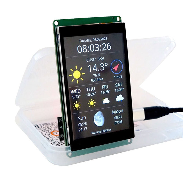
This DIY Color Display Kit is a fun and educational project for makers of all ages. It is a great way to learn about electronics, programming, and improve your soldering skills. Microcontroller As this kit ships with the ePulse Feather ESP32 development board, the kit thereby inherits all the great features of said devkit. Display The large 3.5" 320x480 color display also sports a high-precision capacitive touch interface. Contrary to resistive touch interfaces that often work best when using a stylus this auto-calibrated module offers a smartphone-like user experience. Connector PCB The connectors for the display are already pre-assembled on the connector PCB, as those require a more experienced hand at the soldering iron. Hence, for the inexperienced solderer this offers the best of both worlds. Also, you may choose to not add the on-off switch or the Grove connector; both are optional. The connector PCB offers extendability in two ways: the broken out pins of the microcontroller and the connector for the Grove system. Specifications Microcontroller ESP32 Module ePulse Feather Display Resolution 320 x 480 Display Driver ILI9488 Touch Display Capacitive Included 1x ePulse Feather, low-power ESP32 development board 1x 3.5" 320x480 Color Display (ILI9488, TFT) with capacitive touch Interface (FT6236) Color Kit Grande Connector Board 1x Custom connector PCB to connect the ESP32 and the display Header Pins 1x Set of special pin headers (to be soldered to connector PCB Color Kit Power Switch) 1x On-off switch (to be optionally soldered to connector PCB SMD Grove Connector) 1x Grove connector (to be optionally soldered to connector PCB Color Kit Grande Foam Stickers) 4x Double-sided foam adhesive to secured display to PCB Downloads Schematics Documentation
€ 69,95
Members € 62,96
-
ThingPulse ThingPulse LiPo Battery for Color Kit Grande (900 mAh)
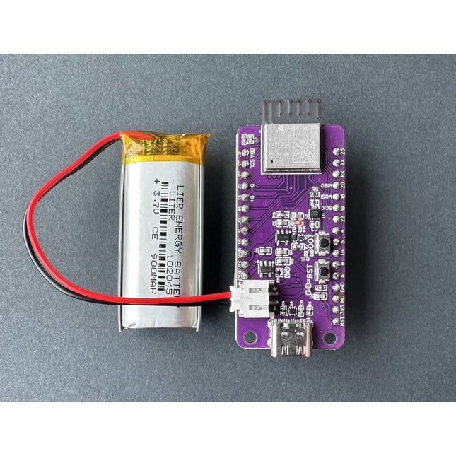
Enhance your ESP32 WiFi Color Display Kit Grande with this high-quality 900 mAh rechargeable lithium-polymer battery! Designed to provide long-lasting power, this battery ensures your projects remain portable and efficient. With its compact size and lightweight design, it’s the perfect accessory for any DIY electronics enthusiast. The battery offers reliable performance, easy integration, and safe, stable power supply, making it ideal for extended use in a variety of applications. 900 mAh LiPo battery JST Connector, fitting ePulse Feather
€ 16,95
Members € 15,26
-
Würth Trilogy of Connectors, 3rd Edition (E-book)
Contents Basic principles A connector is an electromechanical system that provides a separable connection between two subsystems of an electronic device without an unacceptable effect on the performance of the device. It will be shown that there are a lot of complex parameters to handle properly to make this statement true. Design / Selection / Assembly This chapter provides an overview of design and material requirements for contact finishes, contact springs and connector housings as well as the major degradation mechanisms for these connector components. To complete this chapter, material selection criteria for each will also be reviewed. Additionally the Level of Interconnection (LOI) was integrated into this chapter as it addresses, where the connector is used within an electronic system and therefore influences the requirements and durability of the connector depending on its use. Applications This chapter is heading to the practical work and shows how customers use connectors in their applications to offer some possibilities and to ease your daily work. Additionally it contains some special topics like tin-whisker or impedance of ZIF cable to offer you extended background knowledge.
€ 26,99
Members € 21,59
-

Würth Trilogy of Magnetics, 5th Edition (E-book)
Design Guide for EMI Filter Design, SMPS & RF Circuits The book focuses on the selection of components, circuitry and layout recommendations for a wide array of magnetics components, always keeping in mind an EMC point of view. Contents Basic principles The most important laws and foundations of inductive components, equivalent circuit diagrams and simulation models give the reader a basic knowledge of electronics. Components This chapter introduces inductive components and their special properties and areas of use. All relevant components are explained, from EMC components and inductors to transformers, RF components, circuit protection components, shielding materials and capacitors. Applications In this chapter, the reader will find a comprehensive overview of the principle of filter circuits, circuitry and numerous industrial applications that are explained in detail based on original examples.
€ 44,99
Members € 35,99
-
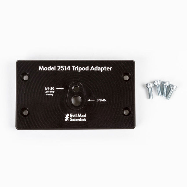
Evil Mad Science Tripod Adapter for AxiDraw
The tripod adapter is custom machined from a solid block of aluminum, and provides two standard tripod mounting points with 3/8-16 and light-duty 1/4-20 thread respectively. This allows you to mount the AxiDraw to a tripod, should you have reason to do so. We would highly recommend using a sturdy tripod with a 3/8-16 connection point and appropriate counterweight (sand bag, lifting weights, etc) to balance the weight of the AxiDraw while in use. Installation is straightforward, and does not require any tools other than those included with AxiDraw: Remove the existing foot pads from the AxiDraw (either standard or outrigger feet, depending on model) and attach this plate to the captured nuts in the bottom surface of the AxiDraw. For AxiDraw SE/A3 (April 2019 and newer), the tripod adapter attaches directly to tapped holes in the base of the machine. This heavy-duty tripod adapter is compatible with AxiDraw V3, AxiDraw V3/A3 and AxiDraw V3 XLX. It is also compatible with AxiDraw SE/A3 manufactured in April 2019 and newer. Specifications Material: Anodized 6061-T6 aluminum Size: 3.90 x 2.36 x 0.35 inches (99.1 x 60 x 8.3 mm) Weight: Approximately 144 g Mounting hardware: included (four M4x10 high-strength steel mounting screws)
€ 29,95
Members € 26,96
-
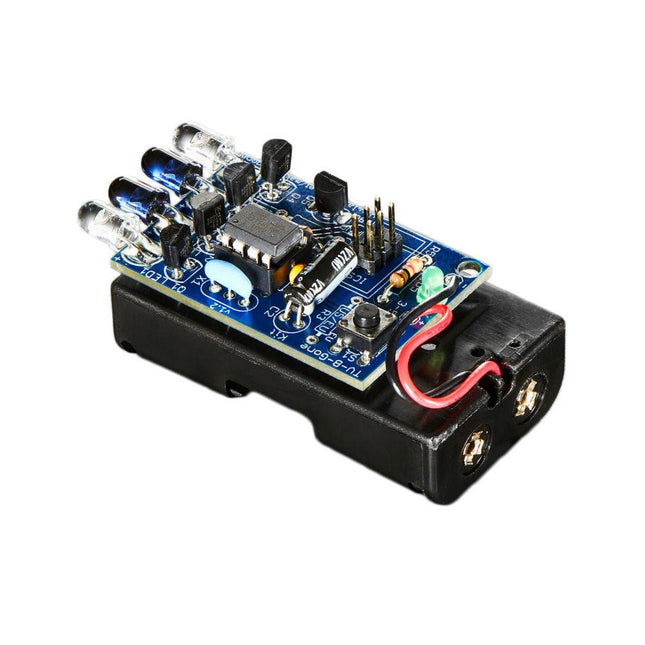
TV-B-Gone TV-B-Gone Kit - Universal TV Remote
The TV-B-Gone universal remote control allows you to turn virtually any TV On or OFF. You control when you see TV, rather than what you see. The TV-B-Gone Keychain remote is so small that it easily fits in your pocket so that you have it handy whenever you need it, wherever you go: bars, restaurants, laundromats, ballparks, arenas, etc.The TV-B-Gone Kit is a great way to teach about electronics. When soldered together, it allows you to turn off almost any television within 150 feet or more. It works on over 230 total power codes – 115 American/Asian and another 115 European codes. You can select which zone you want during kit assembly.This is an unassembled kit which means that soldering and assembly is required – but it’s very easy and a great introduction to soldering in general.This kit makes the popular TV-B-Gone remote more fun because you created it yourself with some basic soldering and assembly! Show your friends and family how technologically savvy you are, and entertain them with the power of the TV-B-Gone!The kit is powered by 2x AA batteries and the output comes from 2x narrow beam IR LEDs and 2x wide-beam IR LEDs.IncludedAll required parts/componentsRequiredTools, soldering iron, and batteriesDownloadsGitHub
€ 29,95
Members € 26,96
-
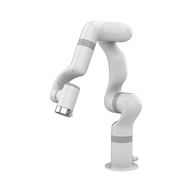
UFactory UFactory 850 Robotic Arm
UFactory 850 is the most powerful robot with industrial grade performance. Features 6DoF Payload: 5 kg Reach: 850 mm Repeatability: 0.02 mm Weight: 20 kg Applications Glambot Welding Screwdriving Robot Vision Industrial Production Designed for both mobile platforms and your workbench The AC control box contains an AC-DC adapter inside, 100-240 V AC is all ready to go. The DC control box supports 48-72 V wide inputs, it perfectly fits the battery system on your mobile platform. Flexible Deployment With Safe Feature Hand teaching, space-saving and easy to re-deploy to multiple applications without changing your production layout. Perfectly for recurrent tasks. Collision detection is available for all of our cobots. Your safety is always the top priority. Graphical Interface For Beginner-Friendly Programming Compatible with various operation systems, including macOS and Windows. Web-based technology compatible with all major browsers. Drag and drop to create your code in minutes. Powerful And Open Source SDK At Your Fingertips Fully functional open-source Python/C++ SDK provides more flexible programming. ROS/ROS2 packages are ready-to-go. Example codes help you to deploy the robotic arm smoothly. Specifications UFactory 850 xArm 5 xArm 6 xArm 7 Payload 5 kg 3 kg 5 kg 3.5 kg Reach 850 mm 700 mm 700 mm 700 mm Degrees of freedom 6 5 6 7 Repeatability ±0.02 mm ±0.1 mm ±0.1 mm ±0.1 mm Maximum Speed 1 m/s 1 m/s 1 m/s 1 m/s Weight (robot arm only) 20 kg 11.2 kg 12.2 kg 13.7 kg Maximum Speed 180°/s 180°/s 180°/s 180°/s Joint 1 ±360° ±360° ±360° ±360° Joint 2 -132°~132° -118°~120° -118°~120° -118°~120° Joint 3 -242°~3.5° -225°~11° -225°~11° ±360° Joint 4 ±360° -97°~180° ±360° -11°~225° Joint 5 -124°~124° ±360° -97°~180° ±360° Joint 6 ±360° ±360° -97°~180° Joint 7 ±360° Hardware Ambient Temperature Range 0-50°C Power Consumption Typical 240 W, max 1000 W Input Power Supply 48 V DC, 20.8 A Footprint Ø 190 mm Materials Aluminum, Carbon Fiber Base Connector Type M8x4 ISO Class Cleanroom 5 Robot Mounting Any End Effector Communication Protocol Modbus RTU End Effector I/O 2x DI / 2x DO / 2x AI / 1x RS485 Communication Mode Ethernet Included 1x UFactory 850 robotic arm 1x AC control box 1x Control box power cable
€ 11.779,00
Members identical
-
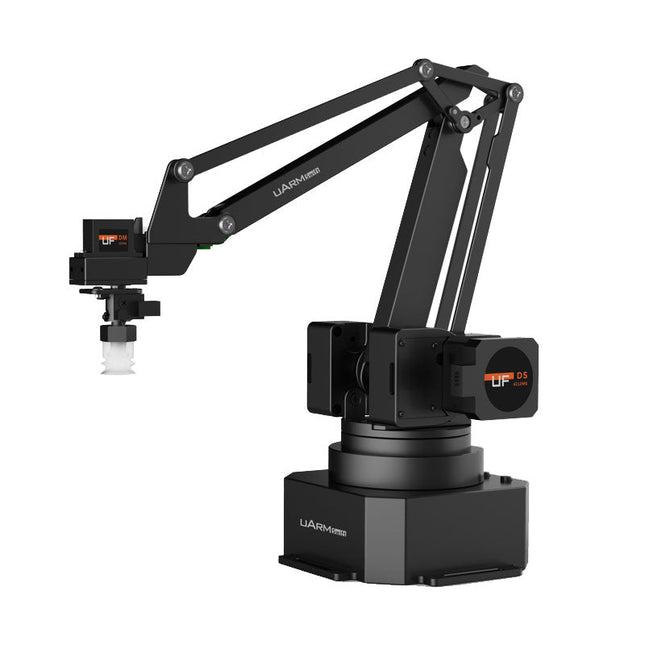
UFactory UFactory uArm Swift Pro
The uArm Swift Pro is a high quality robotic arm that can be used in a wide range of applications. The uArm Swift Pro was developed and optimized for use in education, which means that many packages are already available for open source platforms such as ROS. The uArm Swift Pro has a position repeatability of 0.2 mm and is also equipped with a stepper motor and a 12-bit encoder. These are just a few reasons that make the uArm Swift Pro an excellent choice for educational use. Another great feature is the 3D printing kit that converts the uArm Swift Pro into a 3D printer in less than 1 minute. The uArm supports the following development platforms/systems: UFACTORY SDK Arduino Python ROS GRABCAD OpenMV Smartphone App The smartphone app for iOS is already available in the App Store and enables easy control and monitoring of the robotic arm. The app for Android is in development and will be available soon. An example of the Machine Vision The following GIF shows the uArm in combination with the OpenMV Machine Vision Cam M7 and the facial recognition applications that can be implemented in MicroPython. Specifications Degrees of Freedom: 4 Repeatability: Up to 0.2 mm Payload: 500 g Working Range: 50-320 mm Positioning Speed: 100 m/s Position Feedback: 12-bit Encoder Dimensions: 150 x 140 x 281mm Weight: 2.2 kg Included UFactory uArm Swift Pro Body Bluetooth & Vacuum Gripper Downloads Datasheet
€ 939,00
Members identical
-

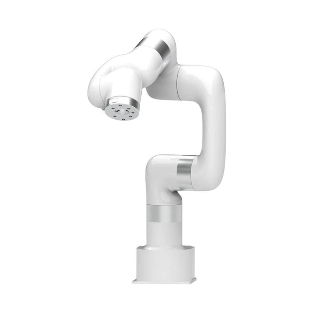
UFactory UFactory xArm 5 Lite
A multi-axis robot perfectly balances power and size Features 5 Axis Payload: 3 kg Reach: 700 mm Repeatability: 0.1 mm Max Speed 1000 mm/s Applications Machine Tending Bin Picking Mobile platform Lab Automation Robotic Research Durable Collaborative robots for your automation Industrial-grade harmonic drive and servomotors guarantee 24/7 working without stop. Crafted from Carbon fiber, 15 kg weight makes it possible for easier deployment. Flexible deployment with safe feature Hand teaching, lightweight, space-saving and easy to re-deploy to multiple applications without changing your production layout. Perfectly for recurrent tasks. Collision detection is available for all of our cobots. Your safety is always the top priority. Graphical interface for beginner-friendly programming Compatible with various of operation systems, including macOS and Windows. Web-based technology compatible with all major browsers. Drag and drop to create your code in minutes. Powerful and open source SDK at your fingertips Fully functional open-source Python/C++ SDK provides more flexible programming. ROS/ROS2 packages are ready-to-go. Example codes help you to deploy the robotic arm smoothly. Specifications UFactory 850 xArm 5 xArm 6 xArm 7 Payload 5 kg 3 kg 5 kg 3.5 kg Reach 850 mm 700 mm 700 mm 700 mm Degrees of freedom 6 5 6 7 Repeatability ±0.02 mm ±0.1 mm ±0.1 mm ±0.1 mm Maximum Speed 1 m/s 1 m/s 1 m/s 1 m/s Weight (robot arm only) 20 kg 11.2 kg 12.2 kg 13.7 kg Maximum Speed 180°/s 180°/s 180°/s 180°/s Joint 1 ±360° ±360° ±360° ±360° Joint 2 -132°~132° -118°~120° -118°~120° -118°~120° Joint 3 -242°~3.5° -225°~11° -225°~11° ±360° Joint 4 ±360° -97°~180° ±360° -11°~225° Joint 5 -124°~124° ±360° -97°~180° ±360° Joint 6 ±360° ±360° -97°~180° Joint 7 ±360° Hardware Ambient Temperature Range 0-50°C Power Consumption Min 8.4 W, Typical 200 W, max 400 W Input Power Supply 24 V DC, 16.5 A Footprint Ø 126 mm Materials Aluminum, Carbon Fiber Base Connector Type M5x5 ISO Class Cleanroom 5 Robot Mounting Any End Effector Communication Protocol Modbus RTU(rs485) End Effector I/O 2x DI/2x DO/2x AI/1x RS485 Communication Mode Ethernet Included 1x xArm 5 robotic arm 1x AC control box 1x Robotic arm power cable 1x Robotic arm end effector adapter cable 1x Robotic arm signal cable 1x Control box power cable 1x Network cable 1x Mounting tool 1x Quick start guide
€ 7.285,00
Members identical
-

UFactory UFactory xArm 6
This multi-axis robot perfectly balances power and size. Features Payload: 5 kg Reach: 700 mm Repeatability: 0.1 mm Max Speed 1000 mm/s Applications Machine Tending Bin Picking Mobile platform Lab Automation Robotic Research Durable Collaborative robots for your automation Industrial-grade harmonic drive and servomotors guarantee 24/7 working without stop. Crafted from Carbon fiber, 15 kg weight makes it possible for easier deployment. Flexible deployment with safe feature Hand teaching, lightweight, space-saving and easy to re-deploy to multiple applications without changing your production layout. Perfectly for recurrent tasks. Collision detection is available for all of our cobots. Your safety is always the top priority. Graphical interface for beginner-friendly programming Compatible with various of operation systems, including macOS and Windows. Web-based technology compatible with all major browsers. Drag and drop to create your code in minutes. Powerful and open source SDK at your fingertips Fully functional open-source Python/C++ SDK provides more flexible programming. ROS/ROS2 packages are ready-to-go. Example codes help you to deploy the robotic arm smoothly. Specifications UFactory 850 xArm 5 xArm 6 xArm 7 Payload 5 kg 3 kg 5 kg 3.5 kg Reach 850 mm 700 mm 700 mm 700 mm Degrees of freedom 6 5 6 7 Repeatability ±0.02 mm ±0.1 mm ±0.1 mm ±0.1 mm Maximum Speed 1 m/s 1 m/s 1 m/s 1 m/s Weight (robot arm only) 20 kg 11.2 kg 12.2 kg 13.7 kg Maximum Speed 180°/s 180°/s 180°/s 180°/s Joint 1 ±360° ±360° ±360° ±360° Joint 2 -132°~132° -118°~120° -118°~120° -118°~120° Joint 3 -242°~3.5° -225°~11° -225°~11° ±360° Joint 4 ±360° -97°~180° ±360° -11°~225° Joint 5 -124°~124° ±360° -97°~180° ±360° Joint 6 ±360° ±360° -97°~180° Joint 7 ±360° Hardware xArm Robot specs Ambient Temperature Range 0-50°C Power Consumption Min 8.4 W, Typical 200 W, max 400 W Input Power Supply 24 V DC, 16.5 A Footprint Ø 126 mm Materials Aluminum, Carbon Fiber Base Connector Type M5x5 ISO Class Cleanroom 5 Robot Mounting Any End Effector Communication Protocol Modbus RTU(rs485) End Effector I/O 2x DI/2x DO/2x AI/1x RS485 Communication Mode Ethernet Included 1x xArm 6 robotic arm 1x AC control box 1x Robotic arm power cable 1x Robotic arm end effector adapter cable 1x Robotic arm signal cable 1x Control box power cable 1x Network cable 1x Mounting tool 1x Quick start guide
€ 11.259,00
Members identical
-
UFactory UFactory xArm 7
This multi-axis robot perfectly balances power and size. Features 6 Axis Payload: 3.5 kg Reach: 700 mm Repeatability: 0.1 mm Max Speed 1000 mm/s Applications Machine Tending Bin Picking Mobile platform Lab Automation Robotic Research Durable Collaborative robots for your automation Industrial-grade harmonic drive and servomotors guarantee 24/7 working without stop. Crafted from Carbon fiber, 15 kg weight makes it possible for easier deployment. Flexible deployment with safe feature Hand teaching, lightweight, space-saving and easy to re-deploy to multiple applications without changing your production layout. Perfectly for recurrent tasks. Collision detection is available for all of our cobots. Your safety is always the top priority. Graphical interface for beginner-friendly programming Compatible with various of operation systems, including macOS and Windows. Web-based technology compatible with all major browsers. Drag and drop to create your code in minutes. Powerful and open source SDK at your fingertips Fully functional open-source Python/C++ SDK provides more flexible programming. ROS/ROS2 packages are ready-to-go. Example codes help you to deploy the robotic arm smoothly. Specifications UFactory 850 xArm 5 xArm 6 xArm 7 Payload 5 kg 3 kg 5 kg 3.5 kg Reach 850 mm 700 mm 700 mm 700 mm Degrees of freedom 6 5 6 7 Repeatability ±0.02 mm ±0.1 mm ±0.1 mm ±0.1 mm Maximum Speed 1 m/s 1 m/s 1 m/s 1 m/s Weight (robot arm only) 20 kg 11.2 kg 12.2 kg 13.7 kg Maximum Speed 180°/s 180°/s 180°/s 180°/s Joint 1 ±360° ±360° ±360° ±360° Joint 2 -132°~132° -118°~120° -118°~120° -118°~120° Joint 3 -242°~3.5° -225°~11° -225°~11° ±360° Joint 4 ±360° -97°~180° ±360° -11°~225° Joint 5 -124°~124° ±360° -97°~180° ±360° Joint 6 ±360° ±360° -97°~180° Joint 7 ±360° Hardware Ambient Temperature Range 0-50°C Power Consumption Min 8.4 W, Typical 200 W, max 400 W Input Power Supply 24 V DC, 16.5 A Footprint Ø 126 mm Materials Aluminum, Carbon Fiber Base Connector Type M5x5 ISO Class Cleanroom 5 Robot Mounting Any End Effector Communication Protocol Modbus RTU(rs485) End Effector I/O 2x DI/2x DO/2x AI/1x RS485 Communication Mode Ethernet Included 1x xArm 7 robotic arm 1x AC control box 1x Robotic arm power cable 1x Robotic arm end effector adapter cable 1x Robotic arm signal cable 1x Control box power cable 1x Network cable 1x Mounting tool 1x Quick start guide
€ 14.569,00
Members identical
-
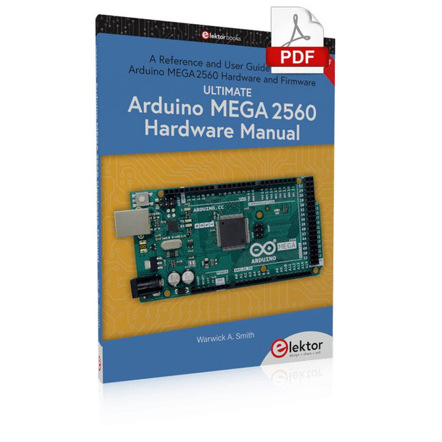
Elektor Digital Ultimate Arduino Mega 2560 Hardware Manual (E-book)
A Reference and User Guide for the Arduino Mega 2560 Hardware and Firmware A manual providing up-to-date hardware information for the Arduino Mega 2560. The Arduino Mega 2560 is an upgrade to the popular Arduino Uno board, providing more pins, serial ports and memory. Arduino is the easy to use open-source electronics platform used by hobbyists, makers, hackers, experimenters, educators and professionals. Get all the information that you need on the hardware and firmware found on Arduino Mega 2560 boards in this handy reference and user guide. Ideal for the workbench or desktop. This manual covers the Arduino Mega 2560 hardware and firmware, and is a companion volume to the Ultimate Arduino Uno Hardware Manual, which covers the Arduino Uno hardware and firmware. Contains all of the Arduino Mega 2560 hardware information in one place Covers Arduino / Genuino Mega 2560 revision 3 and earlier boards Easily find hardware technical specifications with explanations Pin reference chapter with interfacing examples Diagrams and illustrations for easy reference to pin functions and hardware connections Learn to back up and restore firmware on the board, or load new firmware Basic fault finding and repair procedures for Arduino Mega 2560 boards Power supply circuits simplified and explained Mechanical dimensions split into five easy to reference diagrams Contains circuit diagrams, parts list and board layout to easily locate components A chapter on shield compatibility explains how shields work across different Arduino boards
€ 32,95
Members € 26,36
-

Elektor Digital Ultimate Arduino Uno Hardware Manual (E-book)
A Reference and User Guide for the Arduino Uno Hardware and Firmware A manual providing up-to-date hardware information for the popular Arduino Uno, the easy to use open-source electronics platform used by hobbyists, makers, hackers, experimenters, educators and professionals. Get all the information that you need on the hardware and firmware found on Arduino Uno boards in this handy reference and user guide. ldeal for the workbench or desktop Contains all of the Arduino Uno hardware information in one place Covers Arduino / Genuino Uno revision 3 and earlier boards Easily find hardware technical specifications with explanations Pin reference chapter with interfacing examples Diagrams and illustrations for easy reference to alternate pin functions and hardware connections Learn to back up and restore firmware on the board, or load new firmware Basic fault finding and repair procedures for Arduino Uno boards Power supply circuits simplified and explained Mechanical dimensions split into five easy to reference diagrams Contains circuit diagrams, parts list and board layout reference to easily locate components
€ 29,95
Members € 23,96
-

Generic Ultrasonic Distance Sensor (ME007-ULA V1)
This ultrasonic distance sensor (ME007-ULA V1) offers high performance with a robust, waterproof probe. Operating on the principle of ultrasonic echo ranging, the sensor determines the distance to a target by measuring the time elapsed between sending a pulse and receiving the echo. Its non-contact design allows it to detect a wide range of materials, including transparent or non-ferrous objects, metals, non-metals, liquids, solids, and powders. Specifications Detecting Distance 27~800 cm Output Interface RS232, Voltage Analog Operating Voltage 5-12 V Average Current <10 mA Operating Temperature −15~60°C Dimensions 60 x 43 x 31 mm
€ 29,95
Members € 26,96
-
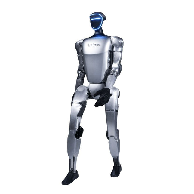
Unitree Unitree G1 Humanoid Robot
The Unitree G1 is a modern humanoid robot that impresses with its remarkable flexibility and advanced technology. With an exceptionally wide range of joint movement and up to 43 joint motors, it exceeds the agility of a typical human. Powered by imitation learning and reinforcement learning, its robotic systems are continuously developed and optimized through artificial intelligence. One of the G1's most impressive features is its ability to autonomously move into a walking position as soon as it touches the ground – no external assistance required! It can immediately start moving, demonstrating a high level of independence and adaptability. The G1 is also equipped with a force-controlled, highly dexterous hand that operates with both sensitivity and precision, thanks to its combination of force and position control. This hand closely mimics human movements, allowing for precise object manipulation. Features Intel RealSense D435 Depth Camera Livox MID-360 3D LiDAR Microphone array (noise and echo cancellation) 5 W stereo speaker Extra large quick release battery Single arm degrees of freedom (shoulder 2 + elbow 2) Hollow joint wiring of the whole machine (no external cables) Maximum torque at joints 120 N.m Single leg degrees of freedom (hip 3, knee 1, ankle 2) Moving speed of 2 m/s Specifications Height, Width and Thickness (Stand) 1320 x 450 x 200 mm Height, Width and Thickness (Fold) 690 x 450 x 300 mm Weight (with Battery) approx. 35 kg Total Degrees of Freedom(Joint Freedom 23 Single Leg Degrees of Freedom 6 Waist Degrees of Freedom 1 Single Arm Degrees of Freedom 5 Joint output bearing Industrial grade crossed roller bearings (high precision, high load capacity) Joint motor Low inertia high-speed internal rotor PMSM (Permanent Magnet Synchronous Motor – better response speed and heat dissipation) Maximum Torque of Knee Joint 90 N.m Arm Maximum Load approx. 2 kg Calf + Thigh Length 0.6 m Arm Span approx. 0.45 m Extra Large Joint Movement Space • Waist joint: Z ±155°• Knee joint: 0~165°• Hip joint: P ±154°, R -30~+170°, Y ±158° Full Joint Hollow Electrical Routing Yes Joint Encoder Dual encoder Cooling System Local air cooling Power Supply 13 string Lithium battery Basic Computing Power 8-core high-performance CPU Sensing Sensor Depth Camera + 3D LiDAR Microphones 4 Microphone Array Speaker 5 W stereo speaker Wireless WiFi 6, Bluetooth 5.2 Smart Battery (Quick Release) 9000 mAh Charger 54 V/5 A Manual Controller Yes Battery Life approx. 2 hours Upgraded Intelligent OTA Yes
€ 24.999,00
Members identical
-

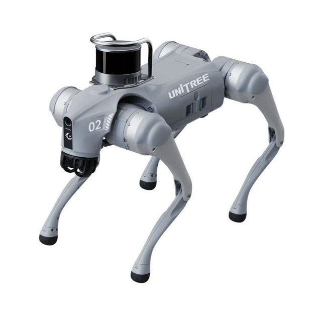
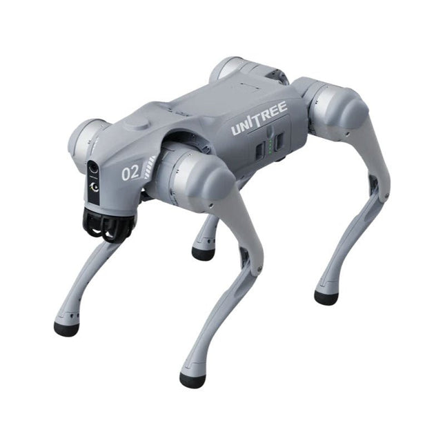
Unitree Unitree Go2 Air Quadruped Robot
Temporary Delay in the Delivery of Unitree Robots Like many other suppliers, we are currently experiencing delays in the delivery of Unitree robots. A shipment from our supplier is currently held in customs, which has unfortunately led to later-than-planned deliveries for previously placed orders. We are actively working with our supplier to resolve this issue and expect more clarity soon, but at this time, we cannot provide any guarantees. Additionally, a new shipment is already on its way, though it will take some time to arrive. Since other suppliers are facing similar challenges, switching to a different provider is unlikely to result in a faster solution. Our top priority remains fulfilling existing orders. If you have any questions or would like to update your order, please do not hesitate to contact our customer service team. We will keep you informed of any further developments. Unitree Go2 series consists of quadruped robots for the research & development of autonomous systems in the fields of human-robot interaction (HRI), SLAM & transportation. Due to the four legs, as well as the 12DOF, this robot can handle a variety of different terrains. The Go2 comes with a perfected drive & power management system, which enables a speed (depending on the version) of up to 3.7 m/s or 11.88 km/h with an operating time of up to 4 hours. Furthermore, the motors have a torque of 45 N.m at the body/thighs and at the knees, which also allow jumps or backflips. Features Super Recognition System: 4D LIDAR L1 Max Running Speed: approx. 5 m/s Peak Joint Torque: approx. 45 N.m Wireless Module: WiFi 6/Bluetooth/4G Ultra-long battery Endurance: approx. 2-4 h (long battery life measured in real life) Intelligent Side-follow System: ISS 2.0 Specifications Tracking module: Remote-controlled or automatic tracking Front camera: Image tansmission Resolution 1280x720, FOV 120°, Ultra wide angle lens deliver rich clarity Front lamp: Brightly lights the way ahead 4D LiDAR L1: 360°x90° omnidirectional ultra-wide-angle scanning allows automatic avoidance with small blind spot and stable operation 12 knee joint motors: Strong and powerful, Beautiful and simple, Brandy new visual experience Intercom microphone: Effective communication with no scenario restrictions Self-retracting strap: Easy to carry and load things More stable, more powerful with advanced devices: 3D LiDAR, 4G ESIM Card, WiFi 6 with Dual-band, Bluetooth 5.2 for stable connection and remote control Powerful Computing Core: Motion controller, High-performance ARM processor, Improved Al algorithm processor, External ORIN NX/NANO Smart battery: Standard 8000 mAh battery, Long-endurance 15000 mAh battery, Protection from over-temp, overcharge and short-circuit Speaker for music play: Listen to music as your pleasure Unitree Go2 Variants The Go2 impresses not only with its technical capabilities, but also with a modern and slim design that gives it a futuristic look and makes it a real eye-catcher. The Go2 Air is specially designed for demos and presentations. With its basic features, it offers a solid basis for demonstrating the movement capabilities and functionality of a four-legged robot. Important: The Go2 Air is delivered without a controller. This can be purchased optionally. With a powerful 8-core high-performance CPU, the Pro and Edu offer impressive computing power required for complex tasks and demanding calculations. This enables faster and more efficient data processing and makes the Pro and Edu a reliable partner for your projects. From the Edu version onwards, the Go2 is programmable and opens up endless possibilities for developing and researching your own robotics applications. The Go2 is also able to handle a step height of up to 14 cm. This makes it an ideal tool for research, education and entry into the world of robotics. The Go2 Edu comes with a remote controller that gives you easy and intuitive control. You also get a docking station with impressive computing power of 100 TOPS, which is equipped with powerful AI algorithms and offers you technical support. Go2 Edu is equipped with a powerful 15000 mAh battery that gives it an impressive runtime of up to 4 hours. This long operating time allows the robot to carry out longer exploration missions and complete demanding tasks. Model Comparison Air Pro Edu/Edu Plus Dimensions (standing) 70 x 31 x 40 cm 70 x 31 x 40 cm 70 x 31 x 40 cm Dimensions (crouching) 76 x 31 x 20 cm 76 x 31 x 20 cm 76 x 31 x 20 cm Material Aluminium alloy + High strength engineering plastic Aluminium alloy + High strength engineering plastic Aluminium alloy + High strength engineering plastic Weight (with battery) about 15 kg about 15 kg about 15 kg Voltage 28~33.6 V 28~33.6 V 28~33.6 V Peaking capacity about 3000 W about 3000 W about 3000 W Payload ≈7 kg (MAX ~ 10 kg) ≈8 kg (MAX ~ 10 kg) ≈8 kg (MAX ~ 12 kg) Speed 0~2.5 m/s 0~3.5 m/s 0~3.7 m/s (MAX ~ 5 m/s) Max Climb Drop Height about 15 cm about 16 cm about 16 cm Max Climb Angle 30° 40° 40° Basic Computing Power N/A 8-core High-performance CPU 8-core High-performance CPU Aluminum knee joint motor 12 set 12 set 12 set Intra-joint circuit (knee) ✓ ✓ ✓ Joint Heat Pipe Cooler ✓ ✓ ✓ Range of Motion Body: −48~48° Body: −48~48° Body: −48~48° Thigh: −200°~90° Thigh: −200°~90° Thigh: −200°~90° Shank: −156°~−48° Shank: −156°~−48° Shank: −156°~−48° Max Torque N/A about 45 N.m about 45 N.m Super-wide-angle 3D LiDAR ✓ ✓ ✓ Wireless Vector Positioning Tracking Module N/A ✓ ✓ HD Wide-angle Camera ✓ ✓ ✓ Foot-end force sensor N/A N/A ✓ Basic Action ✓ ✓ ✓ Auto-scaling strap N/A ✓ N/A Upgraded Intelligent OTA ✓ ✓ ✓ RTT 2.0 Image Transmission ✓ ✓ ✓ App Basic Remote Control ✓ ✓ ✓ App Data Viewing ✓ ✓ ✓ App Graphical Programme ✓ ✓ ✓ Front Lamp (3 W) ✓ ✓ ✓ WiFi 6 with Dual-band ✓ ✓ ✓ Bluetooth 5.2/4.2/2.1 ✓ ✓ ✓ 4G Module N/A CN/GB CN/GB Voice Function N/A ✓ ✓ Music Playback N/A ✓ ✓ ISS 2.0 Intelligent side-follow system N/A ✓ ✓ Intelligent detection and avoidance ✓ ✓ ✓ Secondary development N/A N/A ✓ Manual controller Optional Optional ✓ High computing power module N/A N/A Edu: 40 TOPS computing power Edu Plus: 100 TOPS computing power NVIDIA Jetson Orin (optional) Smart Battery Standard (8000 mAh) Standard (8000 mAh) Long endurance (15000 mAh) Battery Life 1-2 h 1-2 h 2-4 h Charger Standard (33.6 V, 3.5 A) Standard (33.6 V, 3.5 A) Fast charge (33.6 V, 9 A) Included 1x Unitree Go2 Air 1x Unitree Go2 Battery (8000 mAh) Downloads Documentation iOS/Android apps GitHub
€ 2.650,00
Members identical
-
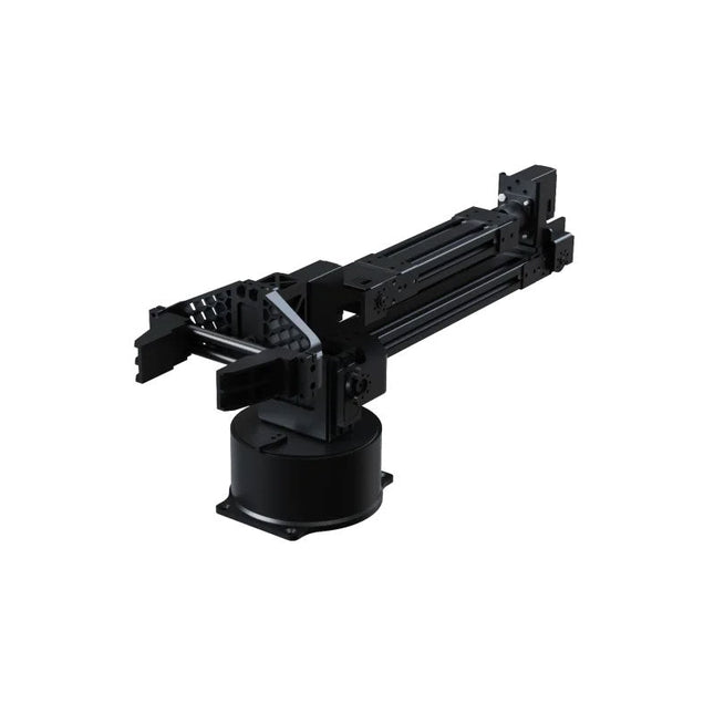
Unitree Unitree Go2 D1 Servo Robotic Arm
The Unitree Go2 D1 Servo Robotic Arm is a high-performance 6-DOF robotic arm, purpose-built for seamless integration with the Unitree Go2 Quadruped Robot. Designed for flexibility and precision, it’s an ideal tool for education, research, automation, and advanced robotics development. Featuring six fully articulated joints and an integrated gripper, the D1 offers true six-axis motion and exceptional freedom of movement. With support for position, velocity, and force control, it enables precise operation across a wide range of tasks – from real-world deployment to experimental learning environments. Constructed from lightweight aluminum alloy, the arm weighs just 2.37 kg while maintaining a reach of 670 mm. This balance of strength and agility makes it well-suited for mobile applications, without compromising stability or range. Thanks to its dual-level interface architecture, the D1 supports both low-level motor commands and high-level behavior programming – giving developers, educators, and researchers full control, whether they’re fine-tuning motion sequences or building complex robotic workflows. Compatible with external components like cameras or mobile robot chassis, the Unitree D1 opens the door to a variety of expanded use cases. Whether it's autonomous object manipulation, AI training, or hands-on robotics education, the D1 transforms any environment into a dynamic and interactive innovation platform. Specifications DoF 6 Axis + 1 Gripper Payload 500 g Arm Reach 550 mm (Gripper not included)670 mm (Gripper included) Interfaces DC5.5-2.1 (Power Supply)RJ45 (Communication)USB-C (Serial Port Debugging) Motor Type Bus Servo Power 60 W Weight 2.37 kg Joint Rotation Range J1: ±135°J2: ±90°J3: ±90°J4: ±135°J5: ±90°J6: ±135°
€ 4.599,00
Members identical
-
Unitree Unitree Go2 Edu Plus 3D LiDAR Quadruped Robot
Temporary Delay in the Delivery of Unitree Robots Like many other suppliers, we are currently experiencing delays in the delivery of Unitree robots. A shipment from our supplier is currently held in customs, which has unfortunately led to later-than-planned deliveries for previously placed orders. We are actively working with our supplier to resolve this issue and expect more clarity soon, but at this time, we cannot provide any guarantees. Additionally, a new shipment is already on its way, though it will take some time to arrive. Since other suppliers are facing similar challenges, switching to a different provider is unlikely to result in a faster solution. Our top priority remains fulfilling existing orders. If you have any questions or would like to update your order, please do not hesitate to contact our customer service team. We will keep you informed of any further developments. Unitree Go2 series consists of quadruped robots for the research & development of autonomous systems in the fields of human-robot interaction (HRI), SLAM & transportation. Due to the four legs, as well as the 12DOF, this robot can handle a variety of different terrains. The Go2 comes with a perfected drive & power management system, which enables a speed (depending on the version) of up to 3.7 m/s or 11.88 km/h with an operating time of up to 4 hours. Furthermore, the motors have a torque of 45 N.m at the body/thighs and at the knees, which also allow jumps or backflips. Features Super Recognition System: 4D LIDAR L1 Max Running Speed: approx. 5 m/s Peak Joint Torque: approx. 45 N.m Wireless Module: WiFi 6/Bluetooth/4G Ultra-long battery Endurance: approx. 2-4 h (long battery life measured in real life) Intelligent Side-follow System: ISS 2.0 Specifications Tracking module: Remote-controlled or automatic tracking Front camera: Image tansmission Resolution 1280x720, FOV 120°, Ultra wide angle lens deliver rich clarity Front lamp: Brightly lights the way ahead 4D LiDAR L1: 360°x90° omnidirectional ultra-wide-angle scanning allows automatic avoidance with small blind spot and stable operation 12 knee joint motors: Strong and powerful, Beautiful and simple, Brandy new visual experience Intercom microphone: Effective communication with no scenario restrictions Self-retracting strap: Easy to carry and load things More stable, more powerful with advanced devices: 3D LiDAR, 4G ESIM Card, WiFi 6 with Dual-band, Bluetooth 5.2 for stable connection and remote control Powerful Computing Core: Motion controller, High-performance ARM processor, Improved Al algorithm processor, External ORIN NX/NANO Smart battery: Standard 8000 mAh battery, Long-endurance 15000 mAh battery, Protection from over-temp, overcharge and short-circuit Speaker for music play: Listen to music as your pleasure Unitree Go2 Variants The Go2 impresses not only with its technical capabilities, but also with a modern and slim design that gives it a futuristic look and makes it a real eye-catcher. The Go2 Air is specially designed for demos and presentations. With its basic features, it offers a solid basis for demonstrating the movement capabilities and functionality of a four-legged robot. Important: The Go2 Air is delivered without a controller. This can be purchased optionally. With a powerful 8-core high-performance CPU, the Pro and Edu offer impressive computing power required for complex tasks and demanding calculations. This enables faster and more efficient data processing and makes the Pro and Edu a reliable partner for your projects. From the Edu version onwards, the Go2 is programmable and opens up endless possibilities for developing and researching your own robotics applications. The Go2 is also able to handle a step height of up to 14 cm. This makes it an ideal tool for research, education and entry into the world of robotics. The Go2 Edu comes with a remote controller that gives you easy and intuitive control. You also get a docking station with impressive computing power of 100 TOPS, which is equipped with powerful AI algorithms and offers you technical support. Go2 Edu is equipped with a powerful 15000 mAh battery that gives it an impressive runtime of up to 4 hours. This long operating time allows the robot to carry out longer exploration missions and complete demanding tasks. Go2 Edu Plus 3D LiDAR comes with a powerful Hesai XT16 3D LiDAR. This LiDAR sensor gives the robot precise three-dimensional perception of its surroundings, enabling smooth navigation and intelligent obstacle avoidance. Model Comparison Air Pro Edu/Edu Plus Dimensions (standing) 70 x 31 x 40 cm 70 x 31 x 40 cm 70 x 31 x 40 cm Dimensions (crouching) 76 x 31 x 20 cm 76 x 31 x 20 cm 76 x 31 x 20 cm Material Aluminium alloy + High strength engineering plastic Aluminium alloy + High strength engineering plastic Aluminium alloy + High strength engineering plastic Weight (with battery) about 15 kg about 15 kg about 15 kg Voltage 28~33.6 V 28~33.6 V 28~33.6 V Peaking capacity about 3000 W about 3000 W about 3000 W Payload ≈7 kg (MAX ~ 10 kg) ≈8 kg (MAX ~ 10 kg) ≈8 kg (MAX ~ 12 kg) Speed 0~2.5 m/s 0~3.5 m/s 0~3.7 m/s (MAX ~ 5 m/s) Max Climb Drop Height about 15 cm about 16 cm about 16 cm Max Climb Angle 30° 40° 40° Basic Computing Power N/A 8-core High-performance CPU 8-core High-performance CPU Aluminum knee joint motor 12 set 12 set 12 set Intra-joint circuit (knee) ✓ ✓ ✓ Joint Heat Pipe Cooler ✓ ✓ ✓ Range of Motion Body: −48~48° Body: −48~48° Body: −48~48° Thigh: −200°~90° Thigh: −200°~90° Thigh: −200°~90° Shank: −156°~−48° Shank: −156°~−48° Shank: −156°~−48° Max Torque N/A about 45 N.m about 45 N.m Super-wide-angle 3D LiDAR ✓ ✓ ✓ Wireless Vector Positioning Tracking Module N/A ✓ ✓ HD Wide-angle Camera ✓ ✓ ✓ Foot-end force sensor N/A N/A ✓ Basic Action ✓ ✓ ✓ Auto-scaling strap N/A ✓ N/A Upgraded Intelligent OTA ✓ ✓ ✓ RTT 2.0 Image Transmission ✓ ✓ ✓ App Basic Remote Control ✓ ✓ ✓ App Data Viewing ✓ ✓ ✓ App Graphical Programme ✓ ✓ ✓ Front Lamp (3 W) ✓ ✓ ✓ WiFi 6 with Dual-band ✓ ✓ ✓ Bluetooth 5.2/4.2/2.1 ✓ ✓ ✓ 4G Module N/A CN/GB CN/GB Voice Function N/A ✓ ✓ Music Playback N/A ✓ ✓ ISS 2.0 Intelligent side-follow system N/A ✓ ✓ Intelligent detection and avoidance ✓ ✓ ✓ Secondary development N/A N/A ✓ Manual controller Optional Optional ✓ High computing power module N/A N/A Edu: 40 TOPS computing power Edu Plus: 100 TOPS computing power NVIDIA Jetson Orin (optional) Smart Battery Standard (8000 mAh) Standard (8000 mAh) Long endurance (15000 mAh) Battery Life 1-2 h 1-2 h 2-4 h Charger Standard (33.6 V, 3.5 A) Standard (33.6 V, 3.5 A) Fast charge (33.6 V, 9 A) Included 1x Unitree Go2 Edu Plus 3D LiDAR 1x Hesai XT16 3D LiDAR 1x Unitree Go2 Remote Controller 1x Unitree Go2 Battery (15000 mAh) 1x Unitree Docking station with 100 TOPS computing power Downloads Documentation iOS/Android apps GitHub
€ 20.599,00
Members identical
-
Unitree Unitree Go2 Edu Plus Quadruped Robot
Temporary Delay in the Delivery of Unitree Robots Like many other suppliers, we are currently experiencing delays in the delivery of Unitree robots. A shipment from our supplier is currently held in customs, which has unfortunately led to later-than-planned deliveries for previously placed orders. We are actively working with our supplier to resolve this issue and expect more clarity soon, but at this time, we cannot provide any guarantees. Additionally, a new shipment is already on its way, though it will take some time to arrive. Since other suppliers are facing similar challenges, switching to a different provider is unlikely to result in a faster solution. Our top priority remains fulfilling existing orders. If you have any questions or would like to update your order, please do not hesitate to contact our customer service team. We will keep you informed of any further developments. Unitree Go2 series consists of quadruped robots for the research & development of autonomous systems in the fields of human-robot interaction (HRI), SLAM & transportation. Due to the four legs, as well as the 12DOF, this robot can handle a variety of different terrains. The Go2 comes with a perfected drive & power management system, which enables a speed (depending on the version) of up to 3.7 m/s or 11.88 km/h with an operating time of up to 4 hours. Furthermore, the motors have a torque of 45 N.m at the body/thighs and at the knees, which also allow jumps or backflips. Features Super Recognition System: 4D LIDAR L1 Max Running Speed: approx. 5 m/s Peak Joint Torque: approx. 45 N.m Wireless Module: WiFi 6/Bluetooth/4G Ultra-long battery Endurance: approx. 2-4 h (long battery life measured in real life) Intelligent Side-follow System: ISS 2.0 Specifications Tracking module: Remote-controlled or automatic tracking Front camera: Image tansmission Resolution 1280x720, FOV 120°, Ultra wide angle lens deliver rich clarity Front lamp: Brightly lights the way ahead 4D LiDAR L1: 360°x90° omnidirectional ultra-wide-angle scanning allows automatic avoidance with small blind spot and stable operation 12 knee joint motors: Strong and powerful, Beautiful and simple, Brandy new visual experience Intercom microphone: Effective communication with no scenario restrictions Self-retracting strap: Easy to carry and load things More stable, more powerful with advanced devices: 3D LiDAR, 4G ESIM Card, WiFi 6 with Dual-band, Bluetooth 5.2 for stable connection and remote control Powerful Computing Core: Motion controller, High-performance ARM processor, Improved Al algorithm processor, External ORIN NX/NANO Smart battery: Standard 8000 mAh battery, Long-endurance 15000 mAh battery, Protection from over-temp, overcharge and short-circuit Speaker for music play: Listen to music as your pleasure Unitree Go2 Variants The Go2 impresses not only with its technical capabilities, but also with a modern and slim design that gives it a futuristic look and makes it a real eye-catcher. The Go2 Air is specially designed for demos and presentations. With its basic features, it offers a solid basis for demonstrating the movement capabilities and functionality of a four-legged robot. Important: The Go2 Air is delivered without a controller. This can be purchased optionally. With a powerful 8-core high-performance CPU, the Pro and Edu offer impressive computing power required for complex tasks and demanding calculations. This enables faster and more efficient data processing and makes the Pro and Edu a reliable partner for your projects. From the Edu version onwards, the Go2 is programmable and opens up endless possibilities for developing and researching your own robotics applications. The Go2 is also able to handle a step height of up to 14 cm. This makes it an ideal tool for research, education and entry into the world of robotics. The Go2 Edu comes with a remote controller that gives you easy and intuitive control. You also get a docking station with impressive computing power of 100 TOPS, which is equipped with powerful AI algorithms and offers you technical support. Go2 Edu is equipped with a powerful 15000 mAh battery that gives it an impressive runtime of up to 4 hours. This long operating time allows the robot to carry out longer exploration missions and complete demanding tasks. Model Comparison Air Pro Edu/Edu Plus Dimensions (standing) 70 x 31 x 40 cm 70 x 31 x 40 cm 70 x 31 x 40 cm Dimensions (crouching) 76 x 31 x 20 cm 76 x 31 x 20 cm 76 x 31 x 20 cm Material Aluminium alloy + High strength engineering plastic Aluminium alloy + High strength engineering plastic Aluminium alloy + High strength engineering plastic Weight (with battery) about 15 kg about 15 kg about 15 kg Voltage 28~33.6 V 28~33.6 V 28~33.6 V Peaking capacity about 3000 W about 3000 W about 3000 W Payload ≈7 kg (MAX ~ 10 kg) ≈8 kg (MAX ~ 10 kg) ≈8 kg (MAX ~ 12 kg) Speed 0~2.5 m/s 0~3.5 m/s 0~3.7 m/s (MAX ~ 5 m/s) Max Climb Drop Height about 15 cm about 16 cm about 16 cm Max Climb Angle 30° 40° 40° Basic Computing Power N/A 8-core High-performance CPU 8-core High-performance CPU Aluminum knee joint motor 12 set 12 set 12 set Intra-joint circuit (knee) ✓ ✓ ✓ Joint Heat Pipe Cooler ✓ ✓ ✓ Range of Motion Body: −48~48° Body: −48~48° Body: −48~48° Thigh: −200°~90° Thigh: −200°~90° Thigh: −200°~90° Shank: −156°~−48° Shank: −156°~−48° Shank: −156°~−48° Max Torque N/A about 45 N.m about 45 N.m Super-wide-angle 3D LiDAR ✓ ✓ ✓ Wireless Vector Positioning Tracking Module N/A ✓ ✓ HD Wide-angle Camera ✓ ✓ ✓ Foot-end force sensor N/A N/A ✓ Basic Action ✓ ✓ ✓ Auto-scaling strap N/A ✓ N/A Upgraded Intelligent OTA ✓ ✓ ✓ RTT 2.0 Image Transmission ✓ ✓ ✓ App Basic Remote Control ✓ ✓ ✓ App Data Viewing ✓ ✓ ✓ App Graphical Programme ✓ ✓ ✓ Front Lamp (3 W) ✓ ✓ ✓ WiFi 6 with Dual-band ✓ ✓ ✓ Bluetooth 5.2/4.2/2.1 ✓ ✓ ✓ 4G Module N/A CN/GB CN/GB Voice Function N/A ✓ ✓ Music Playback N/A ✓ ✓ ISS 2.0 Intelligent side-follow system N/A ✓ ✓ Intelligent detection and avoidance ✓ ✓ ✓ Secondary development N/A N/A ✓ Manual controller Optional Optional ✓ High computing power module N/A N/A Edu: 40 TOPS computing power Edu Plus: 100 TOPS computing power NVIDIA Jetson Orin (optional) Smart Battery Standard (8000 mAh) Standard (8000 mAh) Long endurance (15000 mAh) Battery Life 1-2 h 1-2 h 2-4 h Charger Standard (33.6 V, 3.5 A) Standard (33.6 V, 3.5 A) Fast charge (33.6 V, 9 A) Included 1x Unitree Go2 Edu Plus 1x Unitree Go2 Remote Controller 1x Unitree Go2 Battery (15000 mAh) 1x Unitree Docking station with 100 TOPS computing power Downloads Documentation iOS/Android apps GitHub
€ 14.999,00
Members identical
-

Unitree Unitree Go2 Edu Quadruped Robot
Temporary Delay in the Delivery of Unitree Robots Like many other suppliers, we are currently experiencing delays in the delivery of Unitree robots. A shipment from our supplier is currently held in customs, which has unfortunately led to later-than-planned deliveries for previously placed orders. We are actively working with our supplier to resolve this issue and expect more clarity soon, but at this time, we cannot provide any guarantees. Additionally, a new shipment is already on its way, though it will take some time to arrive. Since other suppliers are facing similar challenges, switching to a different provider is unlikely to result in a faster solution. Our top priority remains fulfilling existing orders. If you have any questions or would like to update your order, please do not hesitate to contact our customer service team. We will keep you informed of any further developments. Unitree Go2 series consists of quadruped robots for the research & development of autonomous systems in the fields of human-robot interaction (HRI), SLAM & transportation. Due to the four legs, as well as the 12DOF, this robot can handle a variety of different terrains. The Go2 comes with a perfected drive & power management system, which enables a speed (depending on the version) of up to 3.7 m/s or 11.88 km/h with an operating time of up to 4 hours. Furthermore, the motors have a torque of 45 N.m at the body/thighs and at the knees, which also allow jumps or backflips. Features Super Recognition System: 4D LIDAR L1 Max Running Speed: approx. 5 m/s Peak Joint Torque: approx. 45 N.m Wireless Module: WiFi 6/Bluetooth/4G Ultra-long battery Endurance: approx. 2-4 h (long battery life measured in real life) Intelligent Side-follow System: ISS 2.0 Specifications Tracking module: Remote-controlled or automatic tracking Front camera: Image tansmission Resolution 1280x720, FOV 120°, Ultra wide angle lens deliver rich clarity Front lamp: Brightly lights the way ahead 4D LiDAR L1: 360°x90° omnidirectional ultra-wide-angle scanning allows automatic avoidance with small blind spot and stable operation 12 knee joint motors: Strong and powerful, Beautiful and simple, Brandy new visual experience Intercom microphone: Effective communication with no scenario restrictions Self-retracting strap: Easy to carry and load things More stable, more powerful with advanced devices: 3D LiDAR, 4G ESIM Card, WiFi 6 with Dual-band, Bluetooth 5.2 for stable connection and remote control Powerful Computing Core: Motion controller, High-performance ARM processor, Improved Al algorithm processor, External ORIN NX/NANO Smart battery: Standard 8000 mAh battery, Long-endurance 15000 mAh battery, Protection from over-temp, overcharge and short-circuit Speaker for music play: Listen to music as your pleasure Unitree Go2 Variants The Go2 impresses not only with its technical capabilities, but also with a modern and slim design that gives it a futuristic look and makes it a real eye-catcher. The Go2 Air is specially designed for demos and presentations. With its basic features, it offers a solid basis for demonstrating the movement capabilities and functionality of a four-legged robot. Important: The Go2 Air is delivered without a controller. This can be purchased optionally. With a powerful 8-core high-performance CPU, the Pro and Edu offer impressive computing power required for complex tasks and demanding calculations. This enables faster and more efficient data processing and makes the Pro and Edu a reliable partner for your projects. From the Edu version onwards, the Go2 is programmable and opens up endless possibilities for developing and researching your own robotics applications. The Go2 is also able to handle a step height of up to 14 cm. This makes it an ideal tool for research, education and entry into the world of robotics. The Go2 Edu comes with a remote controller that gives you easy and intuitive control. You also get a docking station with impressive computing power of 100 TOPS, which is equipped with powerful AI algorithms and offers you technical support. Go2 Edu is equipped with a powerful 15000 mAh battery that gives it an impressive runtime of up to 4 hours. This long operating time allows the robot to carry out longer exploration missions and complete demanding tasks. Model Comparison Air Pro Edu/Edu Plus Dimensions (standing) 70 x 31 x 40 cm 70 x 31 x 40 cm 70 x 31 x 40 cm Dimensions (crouching) 76 x 31 x 20 cm 76 x 31 x 20 cm 76 x 31 x 20 cm Material Aluminium alloy + High strength engineering plastic Aluminium alloy + High strength engineering plastic Aluminium alloy + High strength engineering plastic Weight (with battery) about 15 kg about 15 kg about 15 kg Voltage 28~33.6 V 28~33.6 V 28~33.6 V Peaking capacity about 3000 W about 3000 W about 3000 W Payload ≈7 kg (MAX ~ 10 kg) ≈8 kg (MAX ~ 10 kg) ≈8 kg (MAX ~ 12 kg) Speed 0~2.5 m/s 0~3.5 m/s 0~3.7 m/s (MAX ~ 5 m/s) Max Climb Drop Height about 15 cm about 16 cm about 16 cm Max Climb Angle 30° 40° 40° Basic Computing Power N/A 8-core High-performance CPU 8-core High-performance CPU Aluminum knee joint motor 12 set 12 set 12 set Intra-joint circuit (knee) ✓ ✓ ✓ Joint Heat Pipe Cooler ✓ ✓ ✓ Range of Motion Body: −48~48° Body: −48~48° Body: −48~48° Thigh: −200°~90° Thigh: −200°~90° Thigh: −200°~90° Shank: −156°~−48° Shank: −156°~−48° Shank: −156°~−48° Max Torque N/A about 45 N.m about 45 N.m Super-wide-angle 3D LiDAR ✓ ✓ ✓ Wireless Vector Positioning Tracking Module N/A ✓ ✓ HD Wide-angle Camera ✓ ✓ ✓ Foot-end force sensor N/A N/A ✓ Basic Action ✓ ✓ ✓ Auto-scaling strap N/A ✓ N/A Upgraded Intelligent OTA ✓ ✓ ✓ RTT 2.0 Image Transmission ✓ ✓ ✓ App Basic Remote Control ✓ ✓ ✓ App Data Viewing ✓ ✓ ✓ App Graphical Programme ✓ ✓ ✓ Front Lamp (3 W) ✓ ✓ ✓ WiFi 6 with Dual-band ✓ ✓ ✓ Bluetooth 5.2/4.2/2.1 ✓ ✓ ✓ 4G Module N/A CN/GB CN/GB Voice Function N/A ✓ ✓ Music Playback N/A ✓ ✓ ISS 2.0 Intelligent side-follow system N/A ✓ ✓ Intelligent detection and avoidance ✓ ✓ ✓ Secondary development N/A N/A ✓ Manual controller Optional Optional ✓ High computing power module N/A N/A Edu: 40 TOPS computing power Edu Plus: 100 TOPS computing power NVIDIA Jetson Orin (optional) Smart Battery Standard (8000 mAh) Standard (8000 mAh) Long endurance (15000 mAh) Battery Life 1-2 h 1-2 h 2-4 h Charger Standard (33.6 V, 3.5 A) Standard (33.6 V, 3.5 A) Fast charge (33.6 V, 9 A) Included 1x Unitree Go2 Edu 1x Unitree Go2 Remote Controller 1x Unitree Go2 Battery (15000 mAh) 1x Unitree Docking station with 40 TOPS computing power Downloads Documentation iOS/Android apps GitHub
€ 12.499,00
Members identical
-

Unitree Unitree Go2 Pro Quadruped Robot
Temporary Delay in the Delivery of Unitree Robots Like many other suppliers, we are currently experiencing delays in the delivery of Unitree robots. A shipment from our supplier is currently held in customs, which has unfortunately led to later-than-planned deliveries for previously placed orders. We are actively working with our supplier to resolve this issue and expect more clarity soon, but at this time, we cannot provide any guarantees. Additionally, a new shipment is already on its way, though it will take some time to arrive. Since other suppliers are facing similar challenges, switching to a different provider is unlikely to result in a faster solution. Our top priority remains fulfilling existing orders. If you have any questions or would like to update your order, please do not hesitate to contact our customer service team. We will keep you informed of any further developments. Unitree Go2 series consists of quadruped robots for the research & development of autonomous systems in the fields of human-robot interaction (HRI), SLAM & transportation. Due to the four legs, as well as the 12DOF, this robot can handle a variety of different terrains. The Go2 comes with a perfected drive & power management system, which enables a speed (depending on the version) of up to 3.7 m/s or 11.88 km/h with an operating time of up to 4 hours. Furthermore, the motors have a torque of 45 N.m at the body/thighs and at the knees, which also allow jumps or backflips. Features Super Recognition System: 4D LIDAR L1 Max Running Speed: approx. 5 m/s Peak Joint Torque: approx. 45 N.m Wireless Module: WiFi 6/Bluetooth/4G Ultra-long battery Endurance: approx. 2-4 h (long battery life measured in real life) Intelligent Side-follow System: ISS 2.0 Specifications Tracking module: Remote-controlled or automatic tracking Front camera: Image tansmission Resolution 1280x720, FOV 120°, Ultra wide angle lens deliver rich clarity Front lamp: Brightly lights the way ahead 4D LiDAR L1: 360°x90° omnidirectional ultra-wide-angle scanning allows automatic avoidance with small blind spot and stable operation 12 knee joint motors: Strong and powerful, Beautiful and simple, Brandy new visual experience Intercom microphone: Effective communication with no scenario restrictions Self-retracting strap: Easy to carry and load things More stable, more powerful with advanced devices: 3D LiDAR, 4G ESIM Card, WiFi 6 with Dual-band, Bluetooth 5.2 for stable connection and remote control Powerful Computing Core: Motion controller, High-performance ARM processor, Improved Al algorithm processor, External ORIN NX/NANO Smart battery: Standard 8000 mAh battery, Long-endurance 15000 mAh battery, Protection from over-temp, overcharge and short-circuit Speaker for music play: Listen to music as your pleasure Unitree Go2 Variants The Go2 impresses not only with its technical capabilities, but also with a modern and slim design that gives it a futuristic look and makes it a real eye-catcher. The Go2 Air is specially designed for demos and presentations. With its basic features, it offers a solid basis for demonstrating the movement capabilities and functionality of a four-legged robot. Important: The Go2 Air is delivered without a controller. This can be purchased optionally. With a powerful 8-core high-performance CPU, the Pro and Edu offer impressive computing power required for complex tasks and demanding calculations. This enables faster and more efficient data processing and makes the Pro and Edu a reliable partner for your projects. From the Edu version onwards, the Go2 is programmable and opens up endless possibilities for developing and researching your own robotics applications. The Go2 is also able to handle a step height of up to 14 cm. This makes it an ideal tool for research, education and entry into the world of robotics. The Go2 Edu comes with a remote controller that gives you easy and intuitive control. You also get a docking station with impressive computing power of 100 TOPS, which is equipped with powerful AI algorithms and offers you technical support. Go2 Edu is equipped with a powerful 15000 mAh battery that gives it an impressive runtime of up to 4 hours. This long operating time allows the robot to carry out longer exploration missions and complete demanding tasks. Model Comparison Air Pro Edu/Edu Plus Dimensions (standing) 70 x 31 x 40 cm 70 x 31 x 40 cm 70 x 31 x 40 cm Dimensions (crouching) 76 x 31 x 20 cm 76 x 31 x 20 cm 76 x 31 x 20 cm Material Aluminium alloy + High strength engineering plastic Aluminium alloy + High strength engineering plastic Aluminium alloy + High strength engineering plastic Weight (with battery) about 15 kg about 15 kg about 15 kg Voltage 28~33.6 V 28~33.6 V 28~33.6 V Peaking capacity about 3000 W about 3000 W about 3000 W Payload ≈7 kg (MAX ~ 10 kg) ≈8 kg (MAX ~ 10 kg) ≈8 kg (MAX ~ 12 kg) Speed 0~2.5 m/s 0~3.5 m/s 0~3.7 m/s (MAX ~ 5 m/s) Max Climb Drop Height about 15 cm about 16 cm about 16 cm Max Climb Angle 30° 40° 40° Basic Computing Power N/A 8-core High-performance CPU 8-core High-performance CPU Aluminum knee joint motor 12 set 12 set 12 set Intra-joint circuit (knee) ✓ ✓ ✓ Joint Heat Pipe Cooler ✓ ✓ ✓ Range of Motion Body: −48~48° Body: −48~48° Body: −48~48° Thigh: −200°~90° Thigh: −200°~90° Thigh: −200°~90° Shank: −156°~−48° Shank: −156°~−48° Shank: −156°~−48° Max Torque N/A about 45 N.m about 45 N.m Super-wide-angle 3D LiDAR ✓ ✓ ✓ Wireless Vector Positioning Tracking Module N/A ✓ ✓ HD Wide-angle Camera ✓ ✓ ✓ Foot-end force sensor N/A N/A ✓ Basic Action ✓ ✓ ✓ Auto-scaling strap N/A ✓ N/A Upgraded Intelligent OTA ✓ ✓ ✓ RTT 2.0 Image Transmission ✓ ✓ ✓ App Basic Remote Control ✓ ✓ ✓ App Data Viewing ✓ ✓ ✓ App Graphical Programme ✓ ✓ ✓ Front Lamp (3 W) ✓ ✓ ✓ WiFi 6 with Dual-band ✓ ✓ ✓ Bluetooth 5.2/4.2/2.1 ✓ ✓ ✓ 4G Module N/A CN/GB CN/GB Voice Function N/A ✓ ✓ Music Playback N/A ✓ ✓ ISS 2.0 Intelligent side-follow system N/A ✓ ✓ Intelligent detection and avoidance ✓ ✓ ✓ Secondary development N/A N/A ✓ Manual controller Optional Optional ✓ High computing power module N/A N/A Edu: 40 TOPS computing power Edu Plus: 100 TOPS computing power NVIDIA Jetson Orin (optional) Smart Battery Standard (8000 mAh) Standard (8000 mAh) Long endurance (15000 mAh) Battery Life 1-2 h 1-2 h 2-4 h Charger Standard (33.6 V, 3.5 A) Standard (33.6 V, 3.5 A) Fast charge (33.6 V, 9 A) Included 1x Unitree Go2 Pro 1x Unitree Go2 Battery (8000 mAh) Downloads Documentation iOS/Android apps GitHub
€ 3.599,00
Members identical
-
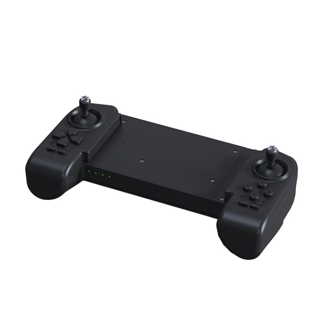
Unitree Unitree Go2 Remote Controller
The Unitree Go2 Controller is a dedicated remote control device designed for seamless and precise operation of the Unitree Go2 Quadruped Robot. This bimanual remote features built-in data transmission and Bluetooth modules, facilitating reliable wireless communication with the robot. It offers an ultra-long control distance of over 100 meters in open environments, ensuring flexibility in various operational scenarios. Specifications Charging Voltage 5 V Charging Current 2 A Frequency 2.4 GHz Communication Modes Data transmission module and Bluetooth Battery Capacity 2500 mAh Operating Time approx. 4.5 hours Control Distance Over 100 meters in open environments
€ 299,00
Members identical
-
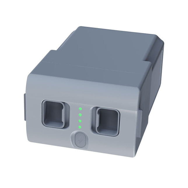
Unitree Unitree Go2 Spare Battery (15,000 mAh)
With a capacity of 15,000 mAh, the Unitree Go2 battery provides a robust power source that enables your robot to complete tasks with ease. Whether for complex exploration, research projects, or fun excursions, this powerful battery delivers the energy your robot needs. The runtime of the Unitree Go2 battery varies depending on the application and usage. Based on the functions and activities employed, the battery can offer between 2 to 4 hours of operation. This flexibility allows you to customize the robot as needed, enabling longer exploration missions or more extensive projects. The Unitree Go2 battery is a reliable companion for your robotics adventures. With its impressive capacity and adaptable runtime, it ensures your robot performs powerfully and with endurance, without frequent recharging. Whether you need the Unitree Go2 battery as a replacement or an upgrade for your robot, this powerful energy storage solution provides the perfect balance of performance and reliability. Specifications Rated voltage: DC 28.8 V Limited charging voltage: DC 33.6 V Charging current: 9 A Rated capacity: 15,000 mAh, 432 Wh Standard: IS 16046 (Part 2) / IEC 62133-2 Self-developed battery management system (BMS) Dimensions: 120 x 80 x 182 mm Functions: Power indicator Self-discharge protection of battery storage Equilibrium charge protection Overcharge protection Discharge protection Short circuit protection Battery charge detection protection
€ 795,00
Members identical
-
Elektor Digital Universal Display Book for PIC Microcontrollers (E-book)
The newcomer to Microchip’s PIC microcontrollers invariably gets an LED to flash as their first attempt to master this technology. You can use just a simple LED indicator in order to show that your initial attempt is working, which will give you confidence to move forward. This is how the book begins — simple programs to flash LEDs, and eventually by stages to use other display indicators such as the 7-segment display, alphanumeric liquid crystal displays and eventually a colour graphic LCD. As the reader progresses through the book, bigger and upgraded PIC chips are introduced, with full circuit diagrams and source code, both in assembler and C. In addition, a small tutorial is included using the MPLAB programming environment, together with the EAGLE schematic and PCB design package to enable readers to create their own designs using the book’s many case studies as working examples to work from.
€ 19,95
Members € 15,96


