Search results for "TINYFPGA"
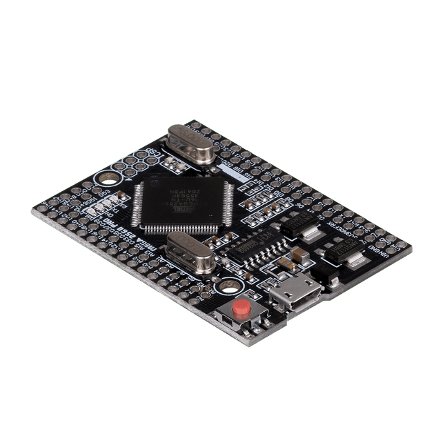
JOY-iT JOY-iT Mega 2560 Pro
This JOY-iT microcontroller board opens the world of programming to you and offers you the same computing power as the Mega 2560, but with a smaller foot-print. It also has many more connectors than comparable boards (Arduino Uno). It is powered by the Arduino IDE and power can be supplied either via the USB port or the VIN pins. This allows you to use it safely with many other devices, e.g. desktop PC. Therefore the Mega 2560 Pro is highly integrable. Features Microcontroller ATmega2560 - 16AU Storage Flash 256 KB, SRAM 8 KB, EEPRom 4 KB Amount of Pins:Digital I/OPWM OutputAnalog Input 541516 Compatible with Arduino, Desktop PCs, etc. Special features USB Port or Power Pins for power supply Interface converter Micro USB to USB UART Size 55 x 38 mm Items delivered JOY-iT Mega 2560 Pro with Pins Further Specifications Input Voltage 7 - 9 Volt on Vin, 5 Volt on mUSB Logic level 5 Volt Output current 800 mA Voltage regulator LDO (for up to 12 V peak) Frequency 16 MHz (12 MHz are possible for data exchange) Download Manual
€ 29,95
Members € 26,96
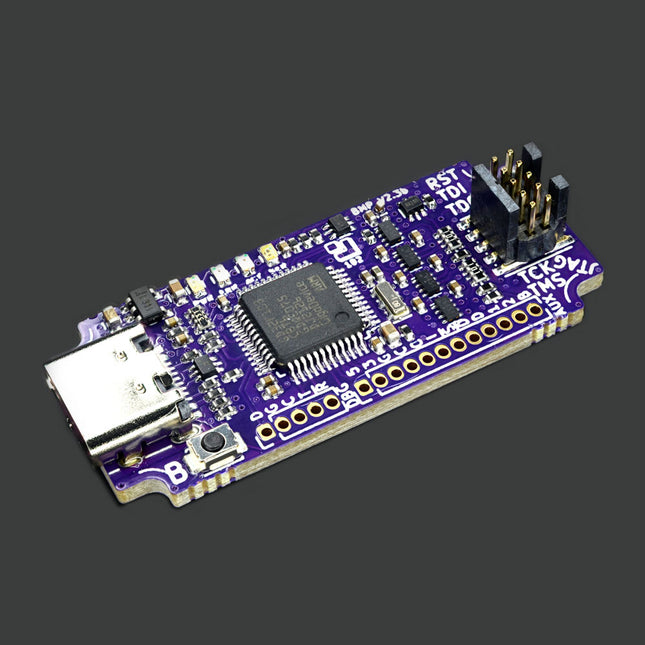
1 Bit Squared Black Magic Probe V2.3 - JTAG/SWD ARM Microcontroller Debugger
Black Magic Probe V2.3 is a JTAG and SWD Adapter with a built-in GDB server used for programming and debugging ARM Cortex MCUs. Its the best friend of any ARM microcontroller developer. All proceeds from BMP hardware sales go directly into the continued development, maintenance and support of the Open-Source Black Magic Debug project. Black Magic Probe gets rid of intermediate programs like OpenOCD or STLink server. This makes the operation faster and more reliable. You just open your GNU Debugger (GDB) and select the virtual com port offered by BMP23 as your extended remote target. For a full description and how-to visit the project website. Features Wide target IO voltage range support, 1.7 V up to 5 V, thanks to VREF referenced level shifters Power switch allowing supply of 3.3 V to the target through the VREF pin Standard ARM-Cortex 0.05' pitch 10pin debug connector Aux UART capable of up to 2 MBaud Small size (4 x 2 x 1 cm) (1.3 x 0.6 x 0.45'), saving space in your field kit and allowing the use of the debugger in very tight spaces and enclosures Jumpers allowing the connection of the UART TX/RX pins to the JTAG/SWD connector resulting in a 'Unified debug' connector TraceSWO UART, decoding hardware support 16 MByte on board flash AUX connector for accessories Mechanical layout allowing easier use of enclosures and mounting into bigger systems. For example: automated pogopin test equipment, automated Hardware In The Loop (HITL) Continous Integration (CI) systems Improved layout, allowing further improvement of the Black Magic Debug firmware reliability and speed using hardware protocol acceleration Included 1x Black Magic Probe Mini V2.3 (BMP23) 1x JTAG Ribbon Cable 1x 0.1' Header Serial Cable 1x 10-pin ARM Cortexto7-pin Adapter 1x UART 0.1' Cable Dimensions 70 x 17 mm (1.3 x 0.6 in) 3.6 g (0.128 oz)
€ 114,95
Members € 103,46
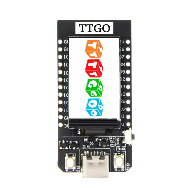
LILYGO LILYGO T-Display ESP32 Development Board (16 MB)
LILYGO T-Display ESP32 WiFi and Bluetooth Module Development Board 1.14-inch LCD Control BoardSpecifications Chipset Espressif-ESP32 240 MHz Xtensa single-/dual-core 32-bit LX6 microprocessor Flash QSPI flash 16 MB SRAM 520 kB SRAM Button Reset USB to TTL CP2104 Modular interface UART, SPI, SDIO, I²C, LED PWM, TV PWM, I²S, IRGPIO, ADC, capacitor touch sensor, DACLNA pre-amplifier Display IPS ST7789V 1.14 Inch Working voltage 2.7-4.2 V Working current About 67 MA Sleep current About 350 uA Working temperature range -40°C ~ +85°C Size & Weight 51.52 x 25.04 x 8.54 mm (7.81 g) Power Supply USB 5 V/1 A Charging current 500 mA Battery 3.7 V lithium battery JST Connector 2-Pin 1.25 mm USB Type-C WiFi Standard FCC/CE-RED/IC/TELEC/KCC/SRRC/NCC (ESP32 chip) Protocol 802.11 b/g/n (802.11n, speed up to 150 Mbps) A-MPDU and A-MSDU polymerization, support 0.4μS Protection interval Frequency range 2.4~2.5 GHz (2400~2483.5 M) Transmit Power 22 dBm Communication distance 300 m Bluetooth Protocol Meet bluetooth v4.2BR/EDR and BLE standard Radio frequency With -97 dBm sensitivity NZIF receiver Class-1, Class-2 & Class-3 emitter AFH Audio frequency CVSD&SBC audio frequency Software Wi-Fi Mode Station/SoftAP/SoftAP+Station/P2P Security mechanism WPA/WPA2/WPA2-Enterprise/WPS Encryption Type AES/RSA/ECC/SHA Firmware upgrade UART download/OTA (Through network/host to download and write firmware) Software Development Support cloud server development /SDK for user firmware development Networking protocol IPv4, IPv6, SSL, TCP/UDP/HTTP/FTP/MQTT User Configuration AT + Instruction set, cloud server, Android/iOS app OS FreeRTOS Included 1x T-Display (16 MB) 1x Charging Cable 2x Pin
€ 24,95
Members € 22,46
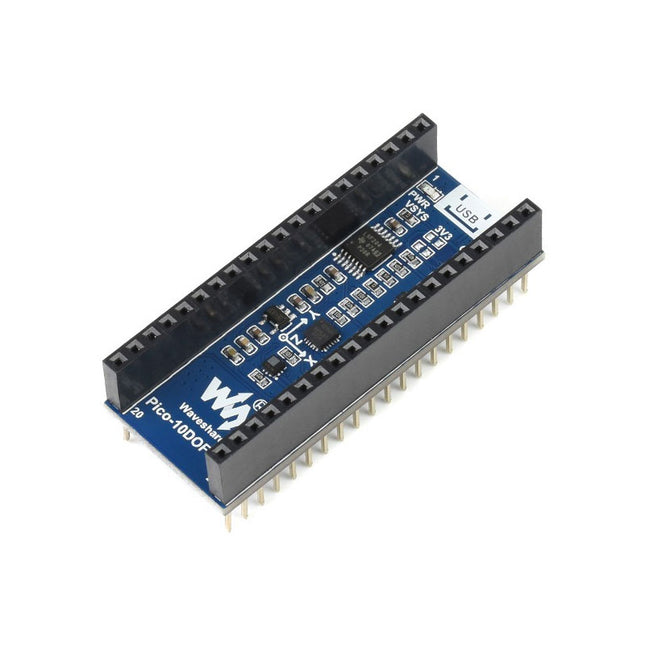
Waveshare Waveshare 10-DOF IMU Sensor Module for Raspberry Pi Pico
The Pico-10DOF-IMU is an IMU sensor expansion module specialized for Raspberry Pi Pico. It incorporates sensors including gyroscope, accelerometer, magnetometer, baroceptor, and uses I²C bus for communication. Combined with the Raspberry Pi Pico, it can be used to collect environment sensing data like temperature and barometric pressure, or to easily DIY a robot that detects motion gesture and orientation. Features Standard Raspberry Pi Pico header, supports Raspberry Pi Pico series Onboard ICM20948 (3-axis gyroscope, 3-axis accelerometer, and 3-axis magnetometer) for detecting motion gesture, orientation, and magnetic field Onboard LPS22HB barometric pressure sensor, for sensing the atmospheric pressure of the environment Comes with development resources and manual (Raspberry Pi Pico C/C++ and MicroPython examples) Specifications Operating voltage 5 V Accelerometer Resolution: 16-bitMeasuring range (configurable): ±2, ±4, ±8, ±16gOperating current: 68.9uA Gyroscope Resolution: 16-bitMeasuring range (configurable): ±250, ±500, ±1000, ±2000°/secOperating current: 1.23mA Magnetometer Resolution: 16-bitMeasuring range: ±4900µTOperating current: 90uA Baroceptor Measuring range: 260 ~ 1260hPaMeasuring accuracy (ordinary temperature): ±0.025hPaMeasuring speed: 1Hz - 75Hz
€ 19,95
Members € 17,96
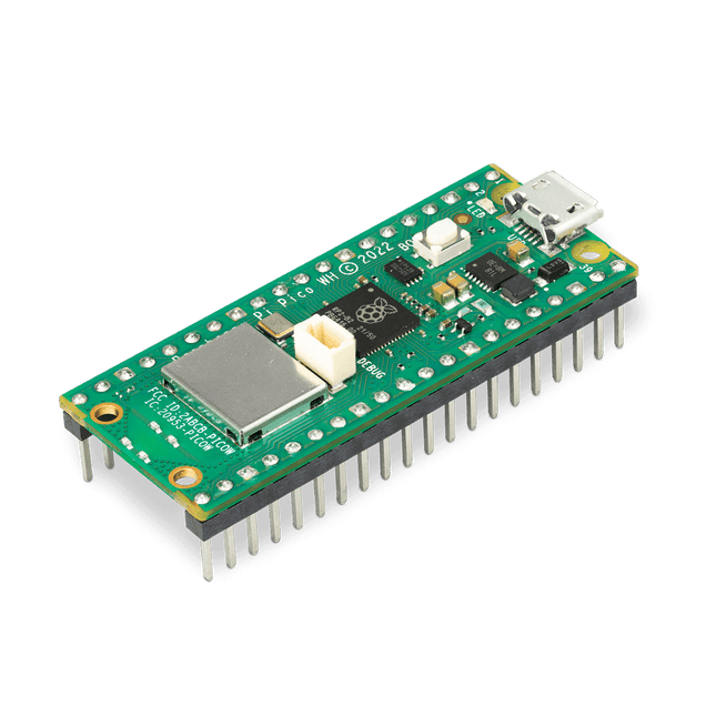
Raspberry Pi Foundation Raspberry Pi Pico RP2040 WH
Raspberry Pi Pico WH is a microcontroller board based on the Raspberry Pi RP2040 microcontroller chip. The RP2040 microcontroller chip ('Raspberry Silicon') offers a dual-core ARM Cortex-M0+ processor (133 MHz), 256 KB RAM, 30 GPIO pins, and many other interface options. In addition, there is 2 MB of on-board QSPI flash memory for code and data storage. Raspberry Pi Pico WH has been designed to be a low cost yet flexible development platform for RP2040 with a 2.4 GHz wireless interface using an Infineon CYW43439. The wireless interface is connected via SPI to the RP2040. Features of Pico WH RP2040 microcontroller with 2 MB of flash memory On-board single-band 2.4 GHz wireless interfaces (802.11n) Micro USB B port for power and data (and for reprogramming the flash) 40 pin 21 x 51 mm 'DIP' style 1 mm thick PCB with 0.1' through-hole pins also with edge castellations Exposes 26 multi-function 3.3 V general purpose I/O (GPIO) 23 GPIO are digital-only, with three also being ADC capable Can be surface mounted as a module 3-pin ARM serial wire debug (SWD) port Simple yet highly flexible power supply architecture Various options for easily powering the unit from micro USB, external supplies or batteries High quality, low cost, high availability Comprehensive SDK, software examples and documentation Pre-populated headers and 3-pin debug connector Features of the RP2040 microcontroller Dual-core cortex M0+ at up to 133 MHz On-chip PLL allows variable core frequency 264 kByte multi-bank high performance SRAM External Quad-SPI Flash with eXecute In Place (XIP) and 16 kByte on-chip cache High performance full-crossbar bus fabric On-board USB1.1 (device or host) 30 multi-function general purpose I/O (four can be used for ADC) 1.8-3.3 V I/O voltage 12-bit 500 ksps analogue to digital converter (ADC) Various digital peripherals 2x UART, 2x I²C, 2x SPI, 16x PWM channels 1x timer with 4 alarms, 1x real time clock 2x programmable I/O (PIO) blocks, 8 state machines in total Flexible, user-programmable high-speed I/O Can emulate interfaces such as SD card and VGA Note: Raspberry Pi Pico W I/O voltage is fixed at 3.3 V. Downloads Datasheet Specifications of 3-pin Debug Connector
€ 9,95
Members identical
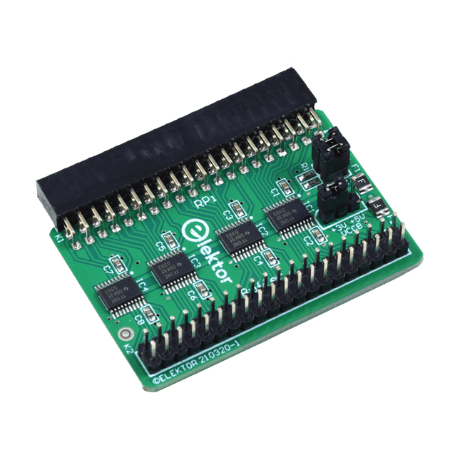
Elektor Labs Elektor Raspberry Pi Buffer Board
When you experiment with the Raspberry Pi on a regular basis and you connect a variety of external hardware to the GPIO port via the header you may well have caused some damage in the past. The Raspberry Pi Buffer Board is there to prevent this! The board is compatible with Raspberry Pi Zero, 3, 4, 5 and 400. All 26 GPIOs are buffered with bi-directional voltage translators to protect the Raspberry Pi when experimenting with new circuits. The PCB is intended to be inserted in the back of Raspberry Pi< 400. The connector to connect to the Raspberry Pi is a right angled 40-way receptacle (2x20). The PCB is only a fraction wider. A 40-way flat cable with appropriate 2x20 headers can be connected to the buffer output header to experiment for instance with a circuit on a breadboard or PCB. The circuit uses four TXS0108E ICs by Texas Instruments. The PCB can also be put upright on a Raspberry Pi 3 or newer. Downloads Schematics Layout
€ 29,95€ 22,95
Members € 20,66
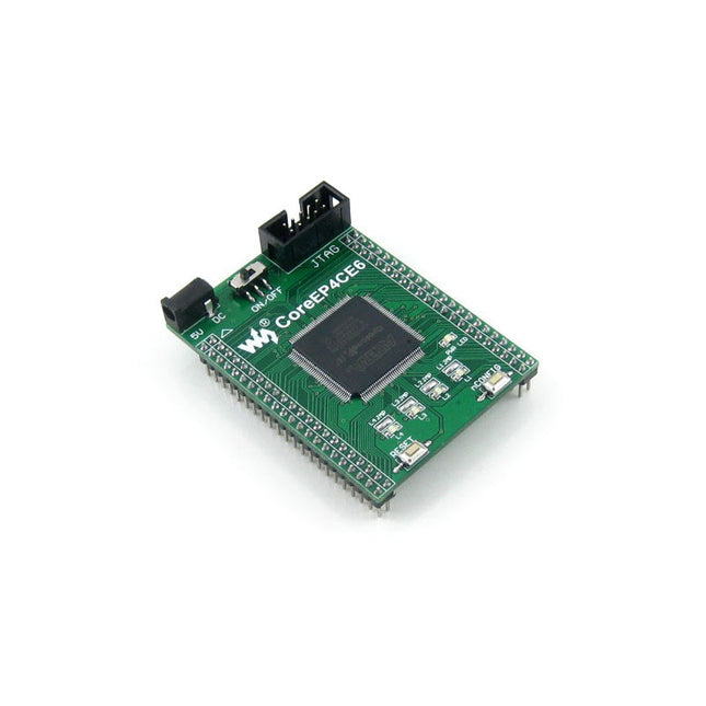
Waveshare Waveshare CoreEP4CE6 (ALTERA Core Board)
Wveshare CoreEP4CE6 is an FPGA core board that features an EP4CE6E22C8N device onboard supporting further expansion. Features Onboard Serial Configuration Device EPCS16SI8N Integrated FPGA basic circuit, such as clock circuit Onboard nCONFIG button, RESET button, 4x LEDs All the I/O ports are accessible on the pin headers Onboard JTAG debugging/programming interface 2.54 mm header pitch design, suitable for being plugged-in your application system Downloads Wiki
€ 49,95
Members € 44,96
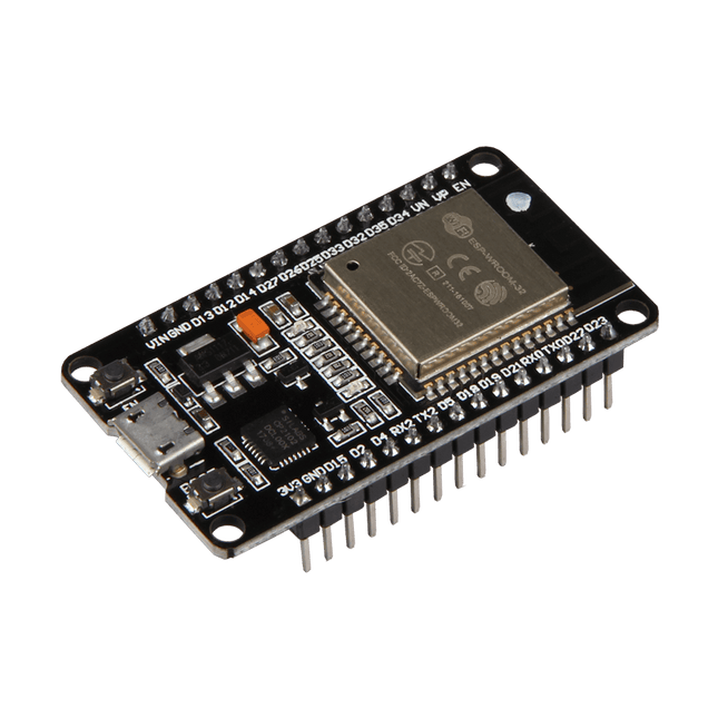
JOY-iT JOY-iT NodeMCU ESP32 Development Board
With the NodeMCU-ESP32, comfortable prototyping is possible with simple programming via Luascript or the Arduino IDE and the breadboard-compatible design. This board has 2.4 GHz dual-mode Wifi and a BT wireless connection. In addition, a 512 KB SRAM and a 4 MB memory are integrated on the microcontroller development board. The board has 21 pins for interface connection, including I²C, SPI, UART, DAC and ADC. Specifications Type ESP32 Processor Tensilica LX6 Dual-Core Clock Frequency 240 MHz SRAM 512 kB Memory 4 MB Wireless Lan 802.11 b/g/n Frequency 2.4 GHz Bluetooth Classic / LE Data Interfaces UART / I²C / SPI / DAC / ADC Operating Voltage 3.3 V (operable via 5 V microUSB) Operating Temperature –40°C – 125°C Dimensions 48 x 26 x 11.5 mm Weight 10 g Downloads Manual
€ 12,95
Members € 11,66
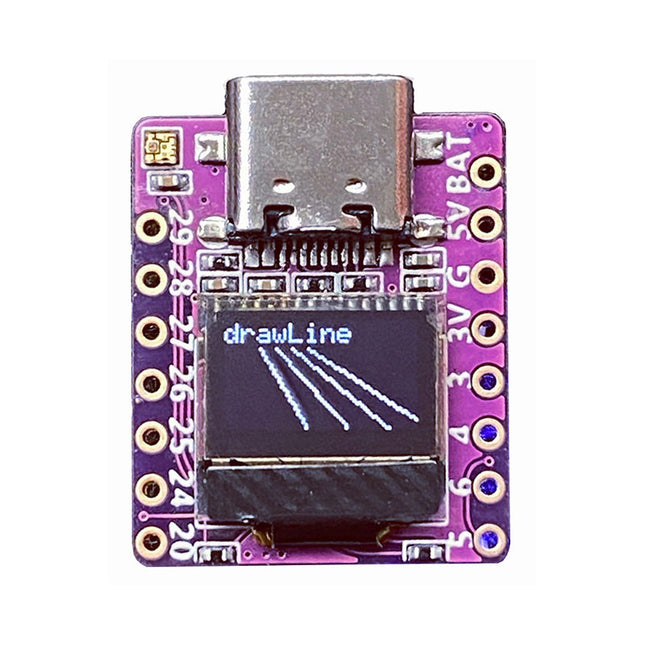
01Space RP2040-0.42LCD Development Board
Arduino, MicroPython, and CircuitPython-compatible compact development board powered by Raspberry Pi RP2040RP2040-0.42LCD is a high-performance development board with integrated 0.42' LCD (70x40 resolution) with flexible digital interfaces.It incorporates Raspberry Pi's RP2040 microcontroller chip. The RP2040 features a dual-core Arm Cortex-M0+ processor clocked at 133 MHz with 264 KB internal SRAM and 2 MB flash storage.Specifications SoC Raspberry Pi RP2040 dual-core Cortex-M0+ microcontroller at up to 125 MHz, with 264 KB SRAM Storage 2 MB SPI flash Display 0.42-inch OLED USB 1x USB Type-C port for power and programming Expansion – Qwiic I²C connector– 7-pin and 8-pin headers with up to 11x GPIOs, 2x SPI, 2x I²C, 4x ADC, 1x UART, 5 V, 3.3 V, VBAT, GND Misc – Reset and Boot buttons– RGB LED, power LED Power supply – 5 V via USB-C port or Vin– VBAT pin for battery input– 3.3 V regulator with 500 mA peak output Dimensions 23.5 x 18 mm Weight 2.5 g DownloadsGitHub
€ 19,95
Members € 17,96
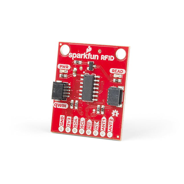
SparkFun SparkFun RFID Qwiic Reader
Plug a reader into the headers, use a Qwiic cable, scan your 125kHz ID tag, and the unique 32-bit ID will be shown on the screen. The unit comes with a read LED and buzzer, but don't worry, there is a jumper you can cut to disable the buzzer if you want. Utilizing SparkFun's handy Qwiic system, no soldering is required to connect it to the rest of your system. However, we still have broken out 0.1'-spaced pins if you prefer to use a breadboard. Utilizing the onboard ATtiny84A, the Qwiic RFID takes the six byte ID tag of your 125kHz RFID card, attaches a timestamp to it, and puts it onto a stack that holds up to 20 unique RFID scans at a time. This information is easy to get at with some simple I²C commands.
€ 24,95€ 14,95
Members identical
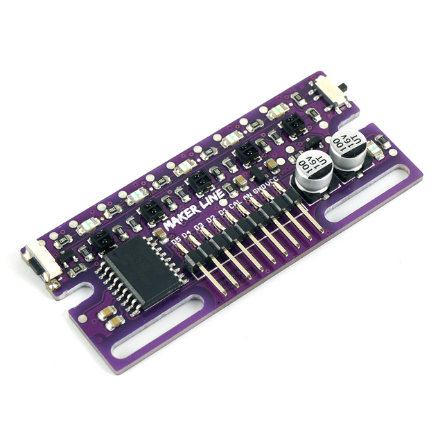
Cytron Cytron Maker Line Sensor
Maker Line is a line sensor with 5 x IR sensors array that is able to track line from 13 mm to 30 mm width. The sensor calibration is also simplified. There is no need to adjust the potentiometer for each IR sensor. You just have to press the calibrate button for 2 seconds to enter calibration mode. Afterwards you need to sweep the sensors array across the line, press the button again and you are good to go. The calibration data is saved in EEPROM and it will stay intact even if the sensor has been powered off. Thus, calibration only needs to be carried out once unless the sensor height, line color or background color has changed. Maker Line also supports dual outputs: 5 x digital outputs for the state of each sensor independently, which is similar to conventional IR sensor, but you get the benefit of easy calibration, and also one analog output, where its voltage represents the line position. Analog output also offers higher resolution compared to individual digital outputs. This is especially useful when high accuracy is required while building a line following robot with PID control. Features Operating Voltage: DC 3.3 V and 5 V compatible (with reverse polarity protection) Recommended Line Width: 13 mm to 30 mm Selectable line color (light or dark) Sensing Distance (Height): 4 mm to 40 mm (Vcc = 5 V, Black line on white surface) Sensor Refresh Rate: 200 Hz Easy calibration process Dual Output Types: 5 x digital outputs represent each IR sensor state, 1 x analog output represents line position. Support wide range of controllers such as Arduino, Raspberry Pi etc. Documentation Datasheet Tutorial: Building A Low-Cost Line Following Robot
€ 14,95
Members € 13,46
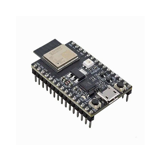
Espressif ESP32-C3-DevKitM-1
ESP32-C3-DevKitM-1 is an entry-level development board based on ESP32-C3-MINI-1, a module named for its small size. This board integrates complete Wi-Fi and Bluetooth LE functions. Most of the I/O pins on the ESP32-C3-MINI-1 module are broken out to the pin headers on both sides of this board for easy interfacing. Developers can either connect peripherals with jumper wires or mount ESP32-C3-DevKitM-1 on a breadboard. Specifications ESP32-C3-MINI-1 ESP32-C3-MINI-1 is a general-purpose Wi-Fi and Bluetooth LE combo module that comes with a PCB antenna. At the core of this module is ESP32-C3FN4, a chip that has an embedded flash of 4 MB. Since flash is packaged in the ESP32-C3FN4 chip, rather than integrated into the module, ESP32-C3-MINI-1 has a smaller package size. 5 V to 3.3 V LDO Power regulator that converts a 5 V supply into a 3.3 V output. 5 V Power On LED Turns on when the USB power is connected to the board. Pin Headers All available GPIO pins (except for the SPI bus for flash) are broken out to the pin headers on the board. For details, please see Header Block. Boot Button Download button. Holding down Boot and then pressing Reset initiates Firmware Download mode for downloading firmware through the serial port. Micro-USB Port USB interface. Power supply for the board as well as the communication interface between a computer and the ESP32-C3FN4 chip. Reset Button Press this button to restart the system. USB-to-UART Bridge Single USB-UART bridge chip provides transfer rates up to 3 Mbps. RGB LED Addressable RGB LED, driven by GPIO 8. Downloads ESP32-C3 Datasheet ESP32-C3-MINI-1 Datasheet ESP32-C3-DevKitM-1 Schematic ESP32-C3-DevKitM-1 PCB Layout ESP32-C3-DevKitM-1 Dimensions
€ 19,95
Members € 17,96


