Search results for "starter OR kit OR for OR gen4 OR ulcd OR 43dct OR clb OR ar OR with OR 4d"
-
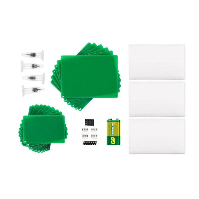
Voltera Voltera Starter Bundle
Kit Contents 1x Standard Nozzles (pack of 4) 1x Burnishing Pads (pack of 3) 1x 2'x3' Substrates (pack of 10) 1x 3'x4' Substrates (pack of 6) 1x 'Hello World' Kit
€ 89,95€ 35,98
Members identical
-

Seeed Studio Seeed Studio Deep Learning Starter Kit for Jetson Nano
The starter kit for Jetson Nano is one of the best kits for beginners to get started with Jetson Nano. This kit includes 32 GB MicroSD card, 20 W adapter, 2-pin jumper, camera, and micro-USB cable. Features 32 GB High-performance MicroSD card 5 V 4 A power supply with 2.1 mm DC barrel connector 2-pin jumper Raspberry Pi camera module V2 Micro-B To Type-A USB cable with DATA enabled
€ 64,95€ 25,98
Members identical
-
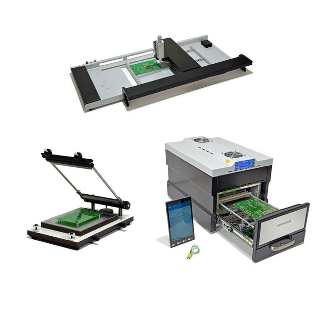
Paggen Werkzeugtechnik SMD Starter I – Production Line for Prototypes
The SMD Starter I prototype production line consists of the stencil printer TSD240, the SMD placement device PlaceMAN and the reflow oven 3LHR10. Stencil printer SD240 (+ Metal Squeegee 155 mm) Stencil size: max. 175 x 255 mm PCB size: max. 180 x 240 mm Size: 410 x 270 x 110 mm Weight: 6.7 kg incl. metal squeegee 155 mm incl. 8 magnets to hold the PCB, 6 of them with M3 grub screw Manual SMD pick-and-place device PlaceMAN for standard components incl. vacuum pump (without feeders, camera, monitor and dispenser) Equipped with smooth-running placement arm, placement head with one-hand operation, rotation of the Z-axis and automatic vacuum switch-off, incl. PCB holder, vacuum unit and 2 placement needles with rubber suction cups. Capacity of feeder (not included) 2x feeder cassette for 10 x 8 mm wheels left 4x feeder cassette for rod feeders for 5 rods each Further feeding systems are possible within the assembly area, e.g. strip-feeder plug-in system Dimensions Base unit (LxWxH): 765 x 390 x 210 mm With feeder cassette for 10 x 8 mm rolls (LxWxH): 765 x 390 x 210 mm With feeder cassette for 10 x 8 mm rolls and feeder cassette for rod feeder (LxWxH): 765 x 430 x 210 mm (height may vary due to rod length) With feeder cassette for 10 x 8 mm rolls incl. holder for 10 rolls and feeder cassette for rod feeder (LxWxH): 765 x 430 x 210 mm (height may vary due to rod length) Specifications Weight of basic unit: approx. 6 kg Axis travel (x,y,z): 470 x 230 x 15 mm Max. working area: 380 x 240 mm Max. PCB size: 230 x 360 mm Power supply: 230/12 V, 800 mA Power supply vacuum pump: 230 V, 6 W 3LHR10 Reflow Oven (programmable for lead-free soldering with manual drawer and tablet control) Reflow oven with IR and convection heating. Forced hot air convection ensures a uniform temperature profile throughout the chamber. After manually opening the door, the fans are turned on and the soldered PCB is quickly cooled. Small reflow oven with manual door Industry 4.0 ready, Bluetooth communication + tablet IR + convection heating Android application to connect to tablet or smartphone 100 different user programs Delivery content: 3LHR10, tablet with app, protective cover for tablet, 4 PCB holders, external thermocouple, manual at tablet Application Connect the oven to the power supply and connect the optionally available extraction system (3LFE10S) to the exhaust air nozzle. After the first turn on, the oven will search for a tablet or smartphone. When both are connected to the Android app, choose the programming of the oven. Here, programmable temperature and preheating time as well as temperature and other data are to be set. Register with the tablet to use the full scope of the software. If the oven is already programmed, the user can control the operation with buttons and display at the front panel. When the reflow process is complete, an audible signal sounds. A signal is also displayed on the tablet/smartphone. The drawer must now be opened manually. The Android application displays process status, time and temperature or other information. Specifications Power supply: 230 V, 50 Hz Maximum power: 3100 W Temperatures: 50-260°C Dimensions: 510 x 370 x 340 mm Maximum weight: 16 kg Grid dimensions: 350 x 220 mm Maximum dimensions of the printed circuit board: 300 x 200 mm Maximum component height on the PCB: 50 mm at the top, 30 mm at the bottom Scope of delivery Stencil printer TSD240 SMD placement device PlaceMAN Reflow oven 3LHR10
€ 6.549,00
Members identical
-
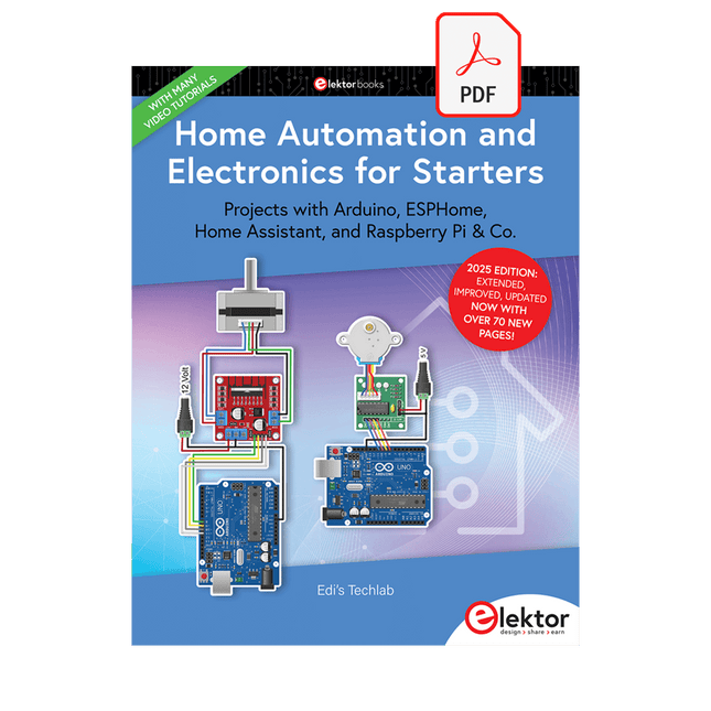
Elektor Digital Home Automation and Electronics for Starters (E-book)
Projects with Arduino, ESPHome, Home Assistant, and Raspberry Pi & Co. This e-book contains various example projects, beginning with an introduction to electronics. It also explains how to install Home Assistant on a Raspberry Pi, how to use indoor climate sensors for temperature and humidity, how to implement the MQTT protocol and other interfaces, and how to use ESPHome to integrate sensors and actuators into Home Assistant. Numerous video tutorials complement the book. Fundamentals of electrical engineering The book begins with an introduction to electrical engineering. You will learn the basics of voltage, current, resistors, diodes and transistors. Arduino and microcontrollers A complete section is dedicated to the Arduino Uno. You will get to know the structure, write your first programs and work on practical examples. Home Assistant and automation You will learn how to set up Home Assistant on a Raspberry Pi and how to use automations, scenes and devices. In addition, Zigbee, MQTT and ESP-NOW – important technologies for home automation – will be discussed. ESP8266, ESP32 and ESP32-CAM The popular ESP microcontrollers are covered in detail. A theoretical introduction is followed by practical projects that show you how to get the most out of these devices. Sensors and actuators The book explains the functionality and application of numerous sensors such as temperature and humidity sensors, motion detectors and RFID readers. For actuators, stepper motors, e-ink displays, servo motors and much more are covered. There are practical application examples for all devices. ESPHome This chapter shows you how to integrate sensors and actuators into Home Assistant without any programming effort. You will be guided step by step through the setup with ESPHome. LEDs and lighting technology In this chapter, you will learn about different types of LEDs and how they can be used. The basics of lighting technology are also explained. Node-RED A whole chapter is dedicated to Node-RED. You will learn the basics of this powerful tool and be guided step by step through its setup and use. Integrated Circuits (ICs) In electronics, there are numerous ICs that make our lives easier. You will get to know the most important ones and apply your knowledge in practical projects. Professional programming Advanced topics such as the correct use of buttons, the use of interrupts and the use of an NTP server for time synchronisation are covered in detail in this chapter. Downloads GitHub
€ 49,95€ 39,95
Members identical
-
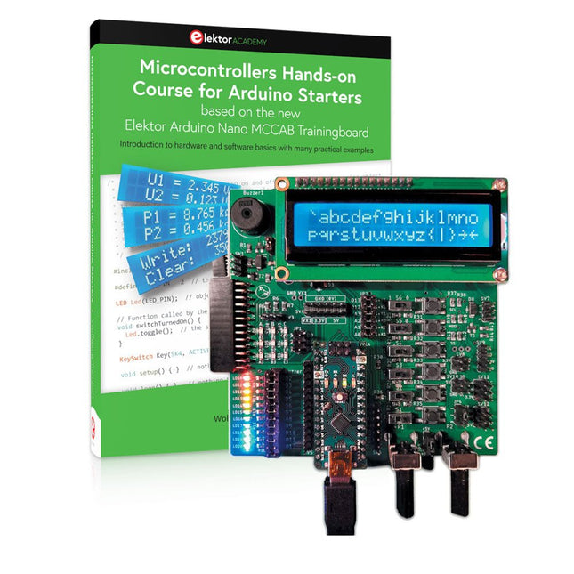
Elektor Bundles Microcontrollers Hands-on Course for Arduino Starters (Bundle)
Realize your own projects with the Elektor Arduino Nano MCCAB Training Board The microcontroller is probably the most fascinating subfield of electronics. Due to the multitude of functions, it combines on its chip, it is a universal multi-tool for developers to realize their projects. Practically every device of daily use today is controlled by a microcontroller. However, for an electronic layman, realizing his own ideas with a microcontroller has so far remained a pipe dream due to its complexity. The Arduino concept has largely simplified the use of microcontrollers, so that now even laymen can realize their own electronics ideas with a microcontroller. Book & Hardware in the Bundle: 'Learning by Doing' This book, which is included in the bundle, shows how you can realize your own projects with a microcontroller even without much experience in electronics and programming languages. It is a microcontrollers hands-on course for starters, because after an overview of the internals of the microcontroller and an introduction to the programming language C, the focus of the course is on the practical exercises. The reader acquires the necessary knowledge by 'learning by doing': in the extensive practical section with 12 projects and 46 exercises, what is learned in the front part of the book is underpinned with many examples. The exercises are structured in such a way that the user is given a task to solve using the knowledge built up in the theoretical part of the book. Each exercise is followed by a sample solution that is explained and commented on in detail, which helps the user to solve problems and compare it with his own solution. Arduino IDE The Arduino IDE is a software development environment that can be downloaded for free to your own PC and that contains the entire software package needed for your own microcontroller projects. You write your programs ('apps') with the IDE’s editor in the C programming language. You translate them into the bits and bytes that the microcontroller understands using the Arduino IDE's built-in compiler, and then load them into the microcontroller's memory on the Elektor Arduino MCCAB Nano Training Board via a USB cable. Query or control external sensors, motors or assemblies In addition to an Arduino Nano microcontroller module, the Elektor Arduino Nano MCCAB Training Board contains all the components required for the exercises, such as light-emitting diodes, switches, pushbuttons, acoustic signal transmitters, etc. External sensors, motors or assemblies can also be queried or controlled with this microcontroller training system. Specifications (Arduino Nano MCCAB Training Board) Power Supply Via the USB connection of the connected PC or an external power supply unit (not included) Operating Voltage +5 Vcc Input Voltage All inputs 0 V to +5 V VX1 and VX2 +8 V to +12 V (only when using an external power supply) Hardware periphery LCD 2x16 characters Potentiometer P1 & P2 JP3: selection of operating voltage of P1 & P2 Distributor SV4: Distributor for the operating voltagesSV5, SV6: Distributor for the inputs/outputs of the microcontroller Switches and buttons RESET button on the Arduino Nano module 6x pushbutton switches K1 ... K6 6x slide switches S1 ... S6 JP2: Connection of the switches with the inputs of the microcontroller Buzzer Piezo buzzer Buzzer1 with jumper on JP6 Indicator lights 11 x LED: Status indicator for the inputs/outputs LED L on the Arduino Nano module, connected to GPIO D13 JP6: Connection of LEDs LD10 ... LD20 with GPIOs D2 ... D12 Serial interfacesSPI & I²C JP4: Selection of the signal at pin X of the SPI connector SV12 SV9 to SV12: SPI interface (3.3 V/5 V) or I²C interface Switching output for external devices SV1, SV7: Switching output (maximum +24 V/160 mA, externally supplied) SV2: 2x13 pins for connection of external modules 3x3 LED matrix(9 red LEDs) SV3: Columns of the 3x3 LED matrix (outputs D6 ... D8) JP1: Connection of the rows with the GPIOs D3 ... D5 Software Library MCCABLib Control of hardware components (switches, buttons, LEDs, 3x3 LED matrix, buzzer) on the MCCAB Training Board Operating Temperature Up to +40 °C Dimensions 100 x 100 x 20 mm Specifications (Arduino Nano) Microcontroller ATmega328P Architecture AVR Operating Voltage 5 V Flash Memory 32 KB, of which 2 KB used by bootloader SRAM 2 KB Clock Speed 16 MHz Analog IN Pins 8 EEPROM 1 KB DC Current per I/O Pins 40 mA on one I/O pin, total maximum 200 mA on all pins together Input Voltage 7-12 V Digital I/O Pins 22 (6 of which are PWM) PWM Output 6 Power Consumption 19 mA Dimensions 18 x 45 mm Weight 7 g Included 1x Elektor Arduino Nano MCCAB Training Board 1x Arduino Nano 1x Book: Microcontrollers Hands-on Course for Arduino Starters
€ 139,95€ 119,95
Members identical
-

SparkFun SparkFun DLI Kit
Reinforcing its commitment to widening the accessibility to and innovation in the area of deep learning, NVIDIA has created a free, self-paced, online Deep Learning Institute (DLI) course, “Getting Started on AI with Jetson Nano.” The course's goal is to build foundational skills to enable anyone to get creative with the Jetson Developer Kit. Please be aware that this kit is for those who already own a Jetson Nano Developer Kit and want to join the DLI Course. A Jetson Nano is not included in this kit. Included in this kit is everything you will need to get started in the “Getting Started on AI with Jetson Nano” (except for a Jetson Nano, of course), and you will learn how to Set up your Jetson Nano and camera Collect image data for classification models Annotate image data for regression models Train a neural network on your data to create your own models Run inference on the Jetson Nano with the models you create The NVIDIA Deep Learning Institute offers hands-on training in AI and accelerated computing to solve real-world problems. Developers, data scientists, researchers, and students can get practical experience powered by GPUs in the cloud and earn a competency certificate to support professional growth. They offer self-paced, online training for individuals, instructor-led workshops for teams, and downloadable course materials for university educators. Included 32 GB microSD Card Logitech C270 Webcam Power Supply 5 V, 4 A USB Cable - microB (Reversible) 2-Pin Jumper Please note: Jetson Nano Developer Kit not included.
€ 79,95€ 31,98
Members identical
-

iFixit iFixit Manta Driver Kit
This kit includes iFixit's widest assortment of bits, complete with every driver head you’ll need to tackle any repair or DIY project. It includes standard bits like Phillips and Flathead in a full range of sizes to handle everything from precision electronics repair to home DIY projects. And it wouldn’t be an iFixit bit set if it didn’t include all the exotic bits from Pentalobes for Apple iPhone and MacBook repair to Gamebits for your vintage Nintendo consoles. All of the next-gen bit sets have been re-designed in order to maximize convenience and usability. The bit set lid is held in place with magnets to increase product lifespan (no more broken hinges or clasps) and also mounts to the back of the bit set case to keep it out of the way while you do your work. If you need help keeping your screws and parts organized, you can use the lid’s integrated sorting tray. The 4 mm bits have been adjusted and have now a longer neck for a deeper and more precise reach. Toolkit Includes Easy-to-Open Magnetized Case Lid with Built-in Sorting Tray 4 mm Aluminum Bit Driver 1/4' Aluminum Bit Driver 4 mm Screwdriver Bits Phillips - 000, 00, 0 Flathead - 1, 1.5, 2, 2.5, 3, 3.5 mm Torx - T2, T3, T4, T5 Torx Security - TR6, TR7, TR8 Pentalobe - P2, P5, P6 JIS - 000, 00, 0, 1 Hex - 0.7, 0.9, 1.3, 1.5 mm Hex Security - 2, 2.5, 3, 3.5 mm Tri-point - Y000, Y00, Y0, Y1 Nut driver - 2.5, 3, 3.5, 4, 4.5, 5, 5.5 mm Gamebit - 3.8, 4.5 mm Spanner - 4, 6 Triangle - 2, 2.2, 2.6, 3 mm Oval Bit iPhone Standoff Bit Sim Eject Bit Magnetic Pickup Bit 1/4' Screwdriver Bits Phillips - 1, 2, 3 Flathead - 4, 5, 6, 7, 8 mm Hex Security - 4, 5, 6, 7, 8 mm Hex Security SAE - 1/8, 9/64, 5/32, 3/16, 7/32, 1/4 Pozidriv - PZ0, PZ1, PZ2, PZ3 Torq-set - 6, 8, 10 Spanner - 8, 10, 12 Square - 0, 1, 2, 3 Spline - M5, M6, M8 Torx Security - TR9, TR10, TR15, TR20, TR25, TR27, TR30, TR35, TR40 Tri-wing 1, 2, 3, 4 Clutch 1, 2, 3 Schrader Valve Hook Drive 1/4' to 4 mm Adapter 1/4' Driver to 1/4' Socket 1/4' Driver to 3/8' Socket 1/4' Socket to 1/4' Driver Specifications Bit Metal: 6150 Steel Driver Material: Anodized Aluminum Case Material: ABS Foam: EVA
€ 64,95
-

Elektor Labs Elektor AM Transmitter Kit
Build Your Own Vintage Radio Broadcaster The Elektor AM Transmitter Kit allows streaming audio to vintage AM radio receivers. Based on a Raspberry Pi Pico microcontroller module, the AM Transmitter can transmit on 32 frequencies in the AM band, from 500 kHz up to 1.6 MHz in 32 steps of approx. 35 kHz. The frequency is selected with a potentiometer and shown on a 0.96" OLED display. A pushbutton allows toggles the transmitting mode between On and Off. The range of the transmitter depends on the antenna. The onboard antenna provides a range of a few centimeters, requiring the AM Transmitter to be placed close to or inside the radio. An external loop antenna (not included) can be connected to increase the range. The Elektor AM Transmitter Kit comes as a kit of parts that you must solder to the board yourself. Features The board is compatible with a Hammond 1593N enclosure (not included).A 5 VDC power supply with micro-USB connector (e.g., an old phone charger) is needed to power the kit (not included). Current consumption is 100 mA. The Arduino software (requiring Earle Philhower’s RP2040 Boards Package) for the Elektor AM Transmitter Kit plus more information is available at the Elektor Labs page of this project. Component List Resistors R1, R4 = 100 Ω R2, R3, R8 = 10 kΩ R5, R6, R9, R10, R11 = 1 kΩ R7 = optional (not included) P1 = potentiometer 100 kΩ, linear Capacitors C1 = 22 µF 16V C2, C4 = 10 nF C3 = 150 pF Miscellaneous K1 = 4×1 pin socket K2, K3 = 3.5 mm socket Raspberry Pi Pico pushbutton, angle mount 0.96" monochrome I²C OLED display PCB 150292-1
€ 34,95€ 29,95
Members identical


-
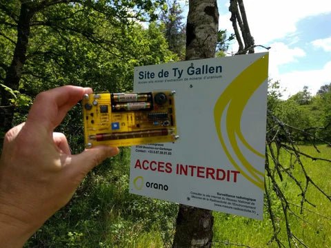
, by Clemens Valens Review: Detect Radiation with the MightyOhm Geiger Counter Kit
The MightyOhm Geiger Counter is a device for detecting beta and gamma radiation levels. Because radiation is so harmful, you may want to keep an...
-
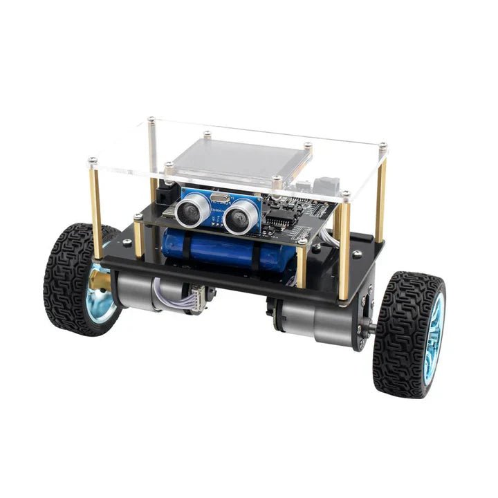
, by Lobna Belarbi Affordable Robot Kits to Kickstart Your Robotics Journey
Robotics is an exciting and rewarding field, but getting started can be intimidating—especially when it comes to choosing the right kit. Fortunately, Elektor offers a...
-
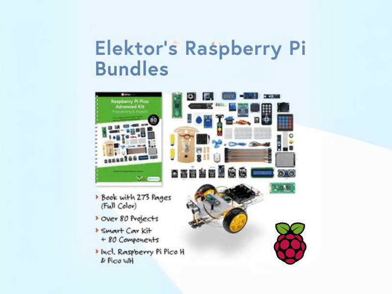
, by Lobna Belarbi Elektor’s Raspberry Pi Bundles: From Beginner-Friendly to Advanced Kits
Find the Perfect Raspberry Pi Bundle for Your Skill Level Whether you're a beginner eager to explore the world of Raspberry Pi or an advanced...
-
, by Lobna Belarbi Must-Have Boards, Kits & Tools to Start Your Arduino Journey with Elektor
Whether you're a newcomer eager to explore the world of microcontrollers or an experienced maker seeking to expand your toolkit, Elektor offers a curated selection...


