Search results for "sparkfun OR datalogger OR iot OR 9dof"
-
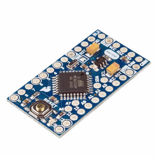
SparkFun SparkFun Arduino Pro Mini 328 (5 V, 16 MHz)
The Arduino Pro Mini is a microcontroller board based on the ATmega328P. It has 14 digital input/output pins (of which 6 can be used as PWM outputs), 6 analog inputs, an on-board resonator, a reset button, and holes for mounting pin headers. A six pin header can be connected to an FTDI cable or SparkFun breakout board to provide USB power and communication to the board. The Arduino Pro Mini is intended for semi-permanent installation in objects or exhibitions. The board comes without pre-mounted headers, allowing the use of various types of connectors or direct soldering of wires. The pin layout is compatible with the Arduino Mini. The Arduino Pro Mini was designed and is manufactured by SparkFun Electronics. Specifications Microcontroller ATmega328P Board Power Supply 5-12 V Circuit Operating Voltage 5 V Digital I/O Pins 14 PWM Pins 6 UART 1 SPI 1 I²C 1 Analog Input Pins 6 External Interrupts 2 DC Current per I/O Pin 40 mA Flash Memory 32 KB of which 2 KB used by bootloader SRAM 2 KB EEPROM 1 KB Clock Speed 16 MHz Dimensions 18 x 33.3 mm (0.7 x 1.3") Downloads Eagle files Schematics
€ 14,95€ 7,95
Best Price
-
Elektor Digital IoT Home Hacks with ESP8266 (E-book)
There are many so-called 'Arduino compatible' platforms on the market. The ESP8266 – in the form of the WeMos D1 Mini Pro – is one that really stands out. This device includes WiFi Internet access and the option of a flash file system using up to 16 MB of external flash memory. Furthermore, there are ample in/output pins (though only one analogue input), PWM, I²C, and one-wire. Needless to say, you are easily able to construct many small IoT devices! This book contains the following builds: A colourful smart home accessory refrigerator controller 230 V power monitor door lock monitor and some further spin-off devices. All builds are documented together with relevant background information for further study. For your convenience, there is a small PCB for most of the designs; you can also use a perf board. You don’t need to be an expert but the minimum recommended essentials include basic experience with a PC, software, and hardware, including the ability to surf the Internet and assemble PCBs. And of course: A handle was kept on development costs. All custom software for the IoT devices and PCB layouts are available for free download from at Elektor.com.
€ 34,95
Members: € 27,96
-

Elektor Publishing MIT App Inventor for AI and IoT
Build Smart Applications with Raspberry Pi, Arduino, and ESP32 Discover how easy and exciting mobile app development can be with MIT App Inventor. This hands-on guide takes you from basic concepts to building real-world mobile applications using a simple visual programming approach—no prior coding experience required. You will create IoT and AI-powered apps for Android devices and explore how App Inventor can also be used with iPhones and iPads. Connect your applications to platforms such as Arduino UNO R4 WiFi, ESP32, Raspberry Pi Pico (2)W and Raspberry Pi 5, enabling you to build smart, connected systems. Inside the book, you will learn how to: Build interactive apps using buttons, images, sound, and multimedia Create text-to-speech and speech-recognition applications Develop camera-based and location-aware (GPS) apps Design useful tools such as calculators and educational apps Work with smartphone sensors like accelerometers and light sensors Build AI-powered applications, including voice assistants and image-generation features Send and receive messages, and create communication-based apps Connect mobile apps to hardware using Wi-Fi and Bluetooth Control real devices such as LEDs, motors, and sensors Designed for beginners, students, and hobbyists, this book focuses on learning by doing. By the end, you will have the skills and confidence to create your own innovative applications that interact with both the digital and physical worlds. Start building and turning your ideas into reality.
€ 44,95
Members: € 40,46
-
Elektor Digital Home Appliance Hack-and-IoT Guidebook (E-book)
Affordable solutions with the ESP8266 and 3D printing If you are looking for a small yet powerful IoT device, you are likely to come across the ESP8266 and compatible products on the market today. One of these, the Wemos/Lolin D1 Mini Pro board strikes a remarkable balance between cost and performance. A small and very affordable prototype board, the D1 Mini Pro stands out with its WiFi functionality and a 16-Mbytes flash memory for easy creation of a flash file system. In addition, there are sufficient input and output pins (only one analog input though) to support PWM, I²C, and One-Wire systems to mention but a few. The book describes the operation, modding, construction, and programming of home appliances including a colorful smart home accessory, a refrigerator/greenhouse controller, an AC powerline monitor, a door lock monitor, and an IKEA Trådfri controller. As a benefit, all firmware developed for these DIY, "IoT-ized" devices can be updated over-the-air (OTA). For most of the designs in the book, a small printed circuit board (PCB) and an enclosure are presented so readers can have a finished and attractive-looking product. Readers having – or with access to! – a 3D printer can "print" the suggested enclosures at home or in a shop. Some of the constructions benefit from a Raspberry Pi configured as a gateway or cms server. This is also described in detail with all the necessary configuring. You don’t need to be an expert but the prerequisites to successful replication of the projects include basic skills with PC software including the ability to surf the Internet. In terms of hardware, you should be comfortable with soldering and generally assembling the PCBs presented in the book. All custom software written for the IoT devices, the PCB layouts, and 3D print files described in the book are available for free downloading.
€ 34,95
Members: € 27,96
-
Elektor Digital IoT GET-U-GOING (E-book)
In 35 Projects with the Raspberry Pi and Arduino The Internet of Things (IoT) is a trend with a strong technological impulse. At home, we want to do everything on our tablets, from browsing Facebook to watching TV, from operating lights to keeping an eye on the temperature. In 35 fun projects, this book will show you how to build your own Internet of Things system. We'll cover the hardware (primarily the Raspberry Pi and Arduino) and the software that makes control via Internet possible. We employ Wi-Fi and radio links so no requirement any longer to install cabling crisscross through your home. Assuming the projects in the book are finished, you have a complete Internet of Things system that allows you to control and view of everything in your home. For example, if there's something in the mail box or the car is securely in the garage. Also, you can switch on the lights and the alarm from your couch. The crisp explanations allow the projects to be customized with ease, for example, to turn on your coffee machine or TV remotely. The index gives easy access to creative projects that can serve as an example, enabling you to do all the connecting to the IoT independently. All project software can be downloaded free of charge from the Elektor website. In this unique book, Raspberry Pi, Arduino and HTML webpages with stylesheets and JavaScript come together in clearly-described, easy-to-build projects. This special book is an essential part of your collection!
€ 34,95
Members: € 27,96
-

Elektor Digital MIT App Inventor for AI and IoT (E-book)
Build Smart Applications with Raspberry Pi, Arduino, and ESP32 Discover how easy and exciting mobile app development can be with MIT App Inventor. This hands-on guide takes you from basic concepts to building real-world mobile applications using a simple visual programming approach—no prior coding experience required. You will create IoT and AI-powered apps for Android devices and explore how App Inventor can also be used with iPhones and iPads. Connect your applications to platforms such as Arduino UNO R4 WiFi, ESP32, Raspberry Pi Pico (2)W and Raspberry Pi 5, enabling you to build smart, connected systems. Inside the book, you will learn how to: Build interactive apps using buttons, images, sound, and multimedia Create text-to-speech and speech-recognition applications Develop camera-based and location-aware (GPS) apps Design useful tools such as calculators and educational apps Work with smartphone sensors like accelerometers and light sensors Build AI-powered applications, including voice assistants and image-generation features Send and receive messages, and create communication-based apps Connect mobile apps to hardware using Wi-Fi and Bluetooth Control real devices such as LEDs, motors, and sensors Designed for beginners, students, and hobbyists, this book focuses on learning by doing. By the end, you will have the skills and confidence to create your own innovative applications that interact with both the digital and physical worlds. Start building and turning your ideas into reality.
€ 34,95
Members: € 27,96
-
Elektor Digital Develop and Operate Your LoRaWAN IoT Nodes (E-book)
Ready-to-use devices and self-built Arduino nodes in the 'The Things Network' LoRaWAN has developed excellently as a communication solution in the IoT. The Things Network (TTN) has contributed to this. The Things Network was upgraded to The Things Stack Community Edition (TTS (CE)). The TTN V2 clusters were closed towards the end of 2021. This book shows you the necessary steps to operate LoRaWAN nodes using TTS (CE) and maybe extend the network of gateways with an own gateway. Meanwhile, there are even LoRaWAN gateways suitable for mobile use with which you can connect to the TTN server via your cell phone. The author presents several commercial LoRaWAN nodes and new, low-cost and battery-powered hardware for building autonomous LoRaWAN nodes. Registering LoRaWAN nodes and gateways in the TTS (CE), providing the collected data via MQTT and visualization via Node-RED, Cayenne, Thingspeak, and Datacake enable complex IoT projects and completely new applications at very low cost. This book will enable you to provide and visualize data collected with battery-powered sensors (LoRaWAN nodes) wirelessly on the Internet. You will learn the basics for smart city and IoT applications that enable, for example, the measurement of air quality, water levels, snow depths, the determination of free parking spaces (smart parking), and the intelligent control of street lighting (smart lighting), among others.
€ 32,95
Members: € 26,36
-
Elektor Digital Programming Voice-controlled IoT Applications with Alexa and Raspberry Pi (E-book)
Learn programming for Alexa devices, extend it to smart home devices and control the Raspberry Pi The book is split into two parts: the first part covers creating Alexa skills and the second part, designing Internet of Things and Smart Home devices using a Raspberry Pi. The first chapters describe the process of Alexa communication, opening an Amazon account and creating a skill for free. The operation of an Alexa skill and terminology such as utterances, intents, slots, and conversations are explained. Debugging your code, saving user data between sessions, S3 data storage and Dynamo DB database are discussed. In-skill purchasing, enabling users to buy items for your skill as well as certification and publication is outlined. Creating skills using AWS Lambda and ASK CLI is covered, along with the Visual Studio code editor and local debugging. Also covered is the process of designing skills for visual displays and interactive touch designs using Alexa Presentation Language. The second half of the book starts by creating a Raspberry Pi IoT 'thing' to control a robot from your Alexa device. This covers security issues and methods of sending and receiving MQTT messages between an Alexa device and the Raspberry Pi. Creating a smart home device is described including forming a security profile, linking with Amazon, and writing a Lambda function that gets triggered by an Alexa skill. Device discovery and on/off control is demonstrated. Next, readers discover how to control a smart home Raspberry Pi display from an Alexa skill using Simple Queue Service (SQS) messaging to switch the display on and off or change the color. A node-RED design is discussed from the basic user interface right up to configuring MQTT nodes. MQTT messages sent from a user are displayed on a Raspberry Pi. A chapter discusses sending a proactive notification such as a weather alert from a Raspberry Pi to an Alexa device. The book concludes by explaining how to create Raspberry Pi as a stand-alone Alexa device.
€ 32,95
Members: € 26,36
-

Elektor Digital Elektor July/August 2024 (PDF)
Elektor GREEN and GOLD members can download their digital edition here. Not a member yet? Click here. Small Thermal Imaging CameraAn Arduino UNO-Based DIY Solution Project Update #3: ESP32-Based Energy MeterIntegration and Testing with Home Assistant 2024: An AI OdysseyEnhancing Object Detection: Integrating Refined Techniques Raspberry Pi Goes AINew Kit Incorporates M.2 HAT+ With AI Accelerator Weather Station SensorsWhich One Should You Choose? AI-Based Water Meter Reading (1)Get Your Old Meter Onto the IoT! A GSM AlarmHarnessing GSM Technology for Remote Garage Safety Low-Power Thread Devices Optimized and ScrutinizedLow Power … Low Effort? From Life’s ExperienceThe Gender Gap DIY Cloud ChamberMaking Invisible Radiation Visible SparkFun Thing Plus MatterA Versatile Matter-Based IoT Development Board IoT RetrofittingMaking RS-232 Devices Fit for Industry 4.0 Enabling IoT with 8-Bit MCUs Technology Drives SustainabilityAdvances Lead to More Efficient Use of Energy in Many Applications AWS for Arduino and Co. (1)Using AWS IoT ExpressLink in Real Life Airflow Detector Using Arduino OnlyNo External Sensors Needed! Water Leak DetectorConnected to Arduino Cloud CrystalsPeculiar Parts, the Series Universal Garden LoggerA Step Towards AI Gardening Analog 1 kHz GeneratorSine Waves with Low Distortion Miletus: Using Web Apps OfflineSystem and Device Access Included! From 4G to 5GIs It Such an Easy Step? Starting Out in Electronics……Balances Out
€ 7,50
-
Elektor Digital Elektor Espressif Guest Edition (PDF)
Elektor GREEN and GOLD members can download their digital edition here. Not a member yet? Click here. Accelerating IoT Innovation A Color E-Ink Wi-Fi Picture Frame ESP-Launchpad TutorialFrom Zero to Flashing in Minutes ESP32 and ChatGPTOn the Way to a Self-Programming System… Walkie-Talkie with ESP-NOWNot Quite Wi-Fi, Not Quite Bluetooth! From Idea to Circuit with the ESP32-S3A Guide to Prototyping with Espressif Chips AIoT Chip InnovationAn Interview With Espressif CEO Teo Swee-Ann Simulate ESP32 with WokwiYour Project’s Virtual Twin Trying Out the ESP32-S3-BOX-3A Comprehensive AIoT Development Platform Electronics Workspace EssentialsInsights and Tips From Espressif Engineers The ESP RainMaker StoryHow We Built “Your” IoT Cloud Assembling the Elektor Cloc 2.0 KitAn Elektor Product Unboxed by Espressif Unleashing the ESP32-P4The Next Era of Microcontrollers Rust + EmbeddedA Development Power Duo Who Are the Rust-Dacious Embedded Developers?How Espressif is Cultivating Embedded Rust for the ESP32 Espressif’s Series of SoCs Building a PLC with Espressif SolutionsWith the Capabilities and Functionality of the ISOBUS Protocol The ESP32-S3 VGA BoardBitluni’s Exciting Journey Into Product Design Acoustic Fingerprinting on ESP32Song Recognition With Open-Source Project Olaf Circular Christmas Tree 2023A High-Tech Way to Celebrate the Holiday Season A Simpler and More Convenient LifeAn Amateur Project Based on the Espressif ESP8266 Module How to Build IoT Apps without Software ExpertiseWith Blynk IoT Platform and Espressif Hardware Building a Smart User Interface on ESP32 Quick & Easy IoT Development with M5Stack Prototyping an ESP32-Based Energy Meter A Value-Added Distributor for IoT and More In-Depth Insights: Interview With Arduino on the Nano ESP32Alessandro Ranellucci and Martino Facchin Discuss Espressif Collaboration Your AIoT Solution ProviderInsights From Espressif Streamlining MCU Development With ESP-IDF Privilege Separation An Open-Source Speech Recognition Server……and the ESP BOX The Thinking EyeFacial Recognition and More Using the ESP32-S3-EYE ESP32-C2-Based Coin Cell SwitchDesign and Performance Evaluation The Smart Home Leaps Forward with MatterUnlocking Smart Home IoT Potential Tech the Future: Where Is Smart Home IoT Headed?
€ 7,50


-
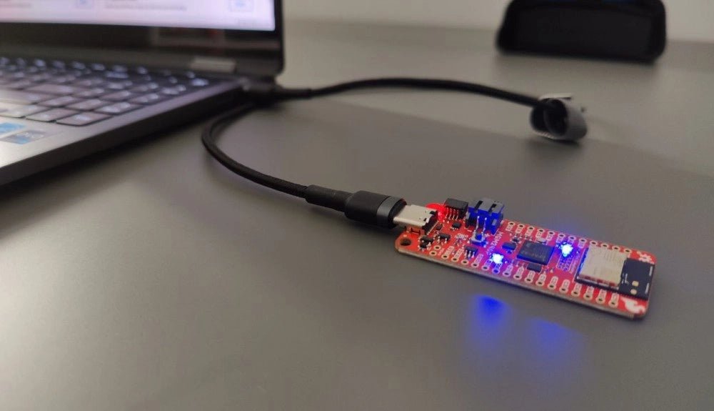
, by Saad Imtiaz SparkFun Thing Plus Matter (MGM240P): A Versatile Matter-Based IoT Development Board (Review)
The SparkFun Thing Plus Matter (MGM240P) is a versatile and feature-rich development board designed for creating Matter-based IoT devices. Matter, formerly known as Project CHIP...
-
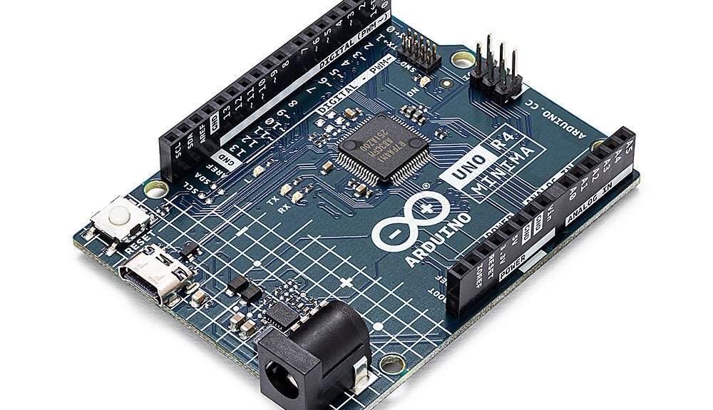
, by Clemens Valens Two New Arduino UNO R4 Boards: Minima and WiFi
The Arduino UNO R4 Minima and the Arduino UNO R4 WiFi have finally hit the shelves, introducing an exciting new chapter for Arduino enthusiasts and...

