Search results for "zy OR 204 OR solderless OR breadboard OR 1660 OR tie OR points"
-

BusBoard BreadBoard BB830T (830 Tie Points) Transparent
The BB830T is a solderless (plug-in) transparent breadboard with 830 connection tie-points (i.e. 830 wire insertion holes). It has 4 power rails. Solderless breadboards are great for building and testing new circuits because parts can be easily inserted and removed. They are completely re-usable. The BB830T has a 630 tie-point IC-circuit area plus four 50 tie-point power rails. Specifications 830 tie points total: 630 tie-point IC-circuit area plus two 100 tie-point distribution strips providing 4 power rails. ABS plastic/transparent body with black printed legend. Color legend on distribution strips. Contacts are Phosphor Bronze with Plated Nickel Finish, rated for 50,000 insertions. Rated at 36 Volts, 2 Amps. Insertion Wire Size is 21 to 26 AWG, 0.016 to 0.028 inches diameter (0.4 to 0.7mm diameter). Peelable adhesive tape backing provided for attaching to a surface. Metal back plate provided.
€ 10,29
-
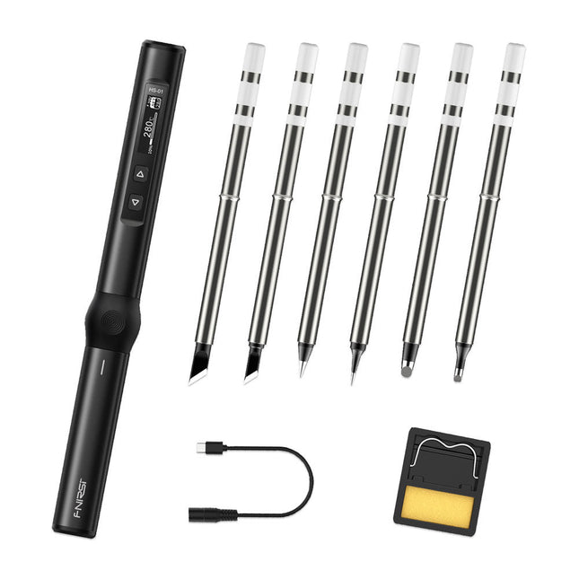
FNIRSI FNIRSI HS-01 Smart Soldering Iron (incl. 6 Soldering Tips)
The perfect tool for quick repairs The FNIRSI HS-01 is a powerful, adjustable smart soldering iron with a built-in 0.87-inch OLED display that quickly reaches temperatures between 80-420°C (180-780°F). The display shows all important information, including the status of the temperature level, the set temperature, the supply voltage and the power percentage. You can set the input voltage from 9-20 V directly in the menu according to your needs. The integrated sleep mode automatically turns off the iron after 30 minutes. Features 96 W input (DC) 65 W PD power OLED display Constant temperature & fast heating CNC metal integral molding Smart safety anti-scald Mini pocket size Ergonomic design Aluminum material Left/right hand switch Efficient heat radiation Inductive sleep Color: Black Specifications Power 65 W Screen 0.87" OLED Operating voltage 9-20 VDC Power supply USB-C Temperature range 80-420°C (180-780°F) Fast charging protocol PD trigger Dimensions 184 x 20 x 20 mm (7.24 x 0.79 x 0.79') Weight 56 g Power Selection Operating voltage 20 V 15 V 12 V 9 V Operating current ≥3.25 A ≥2.5 A ≥2 A ≥1.5 A Power 65 W 37.5 W 24 W 13.5 W Tin melting time 8s 12s 17s 30s Included 1x FNRISI HS-01 smart soldering iron 6x Soldering iron tips (HS01-BC2, HS01-KR, HS01-K65, HS01-B2, HS01-ILS, HS01-BC3) 1x DC to USB-C power cable 1x Mini soldering iron stand 1x Manual Required Power adapter USB-C cable Downloads Manual Firmware V0.3.s19
€ 82,00
-
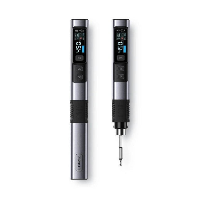
FNIRSI FNIRSI HS-02A Smart Soldering Iron (incl. 6 Soldering Tips)
The FNIRSI HS-02A is an improved version of the HS-01 soldering iron with a better grip and a shorter tip for more comfort and precision during use. It features a larger 0.96-inch IPS HD color display that allows for better visibility of settings and status. With an output power of 100 W, the HS-02A heats up quickly and reaches operating temperature in about 2 seconds. The temperature is adjustable in a range of 100-450°C (212-842°F) to meet different soldering requirements. Features Temperature: 100-450°C (212-842°F) Accurate temperature adjusting and control Fast heating CNC Metal Shell Adaptive Power 100 W High Power Protocols: PD, QC Specifications Temperature Range 100-450°C (212-842°F) Working Voltage 9-20 V Display 0.96" IPS HD Color Screen Power Supply USB-C Fast Charging Protocols PD / QC Power 100 W (max) Dimensions 180 x 20 mm Weight 61 g Included 1x FNRISI HS-02A Smart soldering iron 6x Soldering iron tips (HS02A-KU, HS02A-K, HS02A-JS, HS02A-I, HS02A-C2, HS02A-B) 1x Mini soldering iron stand 1x Manual Downloads Manual Firmware V1.7
€ 61,95
-
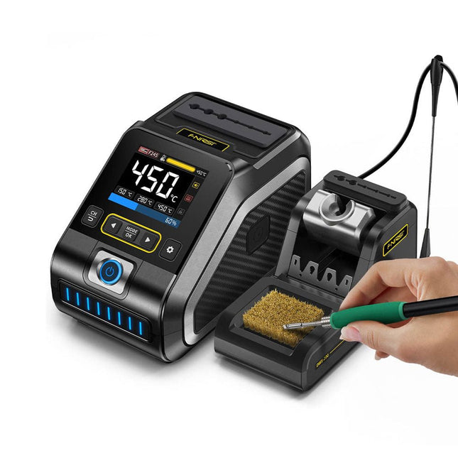
FNIRSI FNIRSI DWS-200 Smart Soldering Station (with F245 Handle + 6 Soldering Tips)
The FNIRSI DWS-200 is a powerful 200 W smart soldering station, ideal for electronic soldering applications. Powered by a switch-mode power supply, it operates smoothly with a wide voltage input range of 100-240 V. The station provides an adjustable temperature range from 100°C to 450°C (212°F to 842°F) and allows for easy switching between °C and °F. To enhance efficiency, it supports up to three preset temperature values and can connect to a soldering iron stand for standby mode activation. The station also features a dynamic temperature curve mode for real-time data monitoring, ensuring precise and consistent performance in demanding soldering tasks. Features Maximum power output of 200 W, allowing for fast heating Wide adaptive voltage input of 100-240 V 2.8" HD color TFT display with intelligent control Multiple preset groups to switch between different settings quickly Supports F245 and F210 soldering handle types, offering flexibility for different soldering applications Real-time sleep mode to extend the life of the soldering tip Multi-mode real-time monitoring for power and temperature status, enhancing safety and precision Specifications Peak Power 200 W (max) Temperature Range 100°C~450°C (212°F~842°F) Display 2.8" TFT HD Color Screen Heating Time 1 sec Melting Time 3 sec Input Voltage 100-240 V (AC) Input Fuse 3 A Soldering Handle Type F245 Dimensions (Station) 156 x 96 x 103 mm Weight (Station) 475 g Included 1x FNIRSI DWS-200 Soldering Station 1x Soldering Handle F245 6x Soldering Tips (B, KU, K, C2, I, JS) 1x Connecting Cable 2x Helping Hands 1x Power Cable (EU) Downloads Manual Firmware V1.3
€ 179,00
-
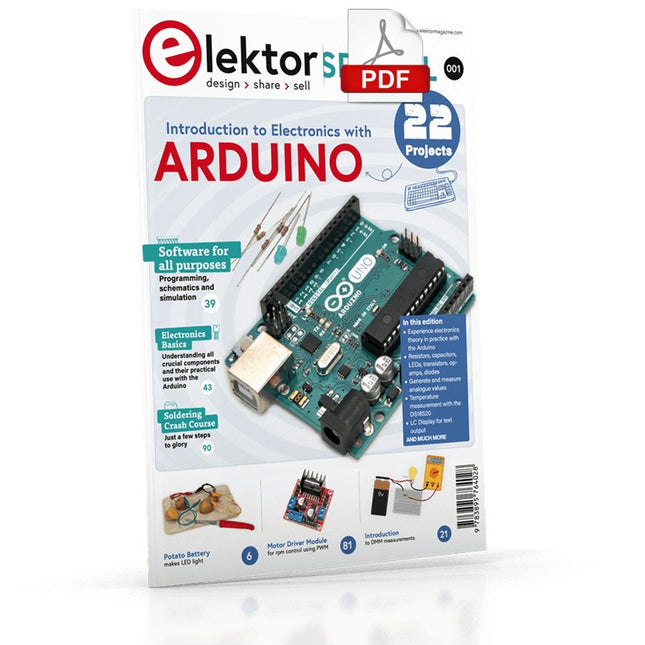
Elektor Digital Elektor Special: Introduction to Electronics with Arduino (PDF)
Although the Arduino isn’t a novelty any longer, there are still many beginners who want to try programming and development with a microcontroller, and to them, it is all new. All beginnings can be difficult, though they should be light and enjoyable. You do not need much or expensive equipment for the examples. The circuits are built on a small breadboard, and, if necessary, connected to an Arduino Uno, which you can program on a Windows PC. You will find clear examples of how to build all circuits, ensuring easy and error-free reproduction. Projects Discussed Current & Voltage – How it all began Arduino Hardware Arduino Programming The Electrical Circuit Measuring with the Multimeter Circuit Diagrams and Breadboards Creating Circuit Diagrams Breadboard Views with Fritzing Online Circuit Simulation Indispensable: Resistors (Part 1) Hands-on with Resistors (Part 2) Variable Resistors Diodes: One-way Street for Current The Transistor Switch Electromagnetism Relays and Motors op-amps: Operational Amplifiers Capacitors The NE555 Timer PWM and Analogue Values with Arduino 7-Segment Temperature Display Introduction to Soldering and LCDs
€ 11,95
Members € 10,76
-
Elektor Digital Experiments with Digital Electronics (E-book)
The field of digital electronics is central to modern technology. This e-book presents fundamental circuits using gates, flip-flops and counters from the CMOS 4000 Series. Each of the 50 experiments has a circuit diagram as well as a detailed illustration of the circuit’s construction on solderless breadboard. Learning these fundamentals is best done using practical experiments. Building these digital circuits will improve your knowledge and will be fun to boot. Many of the circuits presented here have practical real-life applications. With a good overview of the field, you’ll be well equipped to find simple and cost-effective solutions for any application. The e-book is targeted essentially at students, trainees and anyone with an interest in and requiring an introduction to digital control electronics. Moreover, the knowledge gleaned here is the foundation for further projects in the field of microcontrollers and programming.
€ 24,95
Members € 19,96
-

Elektor Digital The Book of 555 Timer Projects (E-book)
Over 45 Builds for the Legendary 555 Chip (and the 556, 558) The 555 timer IC, originally introduced by the Signetics Corporation around 1971, is sure to rank high among the most popular analog integrated circuits ever produced. Originally called the IC Time Machine, this chip has been used in many timer-related projects by countless people over decades. This book is all about designing projects based on the 555 timer IC. Over 45 fully tested and documented projects are presented. All projects have been fully tested by the author by constructing them individually on a breadboard. You are not expected to have any programming experiences for constructing or using the projects given in the book. However, it’s definitely useful to have some knowledge of basic electronics and the use of a breadboard for constructing and testing electronic circuits. Some of the projects in the book are: Alternately Flashing Two LEDs Changing LED Flashing Rate Touch Sensor On/Off Switch Switch On/Off Delay Light-Dependent Sound Dark/Light Switch Tone Burst Generator Long Duration Timer Chasing LEDs LED Roulette Game Traffic Lights Continuity Tester Electronic Lock Switch Contact Debouncing Toy Electronic Organ Multiple Sensor Alarm System Metronome Voltage Multipliers Electronic Dice 7-Segment Display Counter Motor Control 7-Segment Display Dice Electronic Siren Various Other Projects The projects given in the book can be modified or expanded by you for your very own applications. Electronic engineering students, people engaged in designing small electronic circuits, and electronic hobbyists should find the projects in the book instructive, fun, interesting, and useful.
€ 29,95
Members € 23,96
-

Elektor Publishing The Book of 555 Timer Projects
Over 45 Builds for the Legendary 555 Chip (and the 556, 558) The 555 timer IC, originally introduced by the Signetics Corporation around 1971, is sure to rank high among the most popular analog integrated circuits ever produced. Originally called the IC Time Machine, this chip has been used in many timer-related projects by countless people over decades. This book is all about designing projects based on the 555 timer IC. Over 45 fully tested and documented projects are presented. All projects have been fully tested by the author by constructing them individually on a breadboard. You are not expected to have any programming experiences for constructing or using the projects given in the book. However, it’s definitely useful to have some knowledge of basic electronics and the use of a breadboard for constructing and testing electronic circuits. Some of the projects in the book are: Alternately Flashing Two LEDs Changing LED Flashing Rate Touch Sensor On/Off Switch Switch On/Off Delay Light-Dependent Sound Dark/Light Switch Tone Burst Generator Long Duration Timer Chasing LEDs LED Roulette Game Traffic Lights Continuity Tester Electronic Lock Switch Contact Debouncing Toy Electronic Organ Multiple Sensor Alarm System Metronome Voltage Multipliers Electronic Dice 7-Segment Display Counter Motor Control 7-Segment Display Dice Electronic Siren Various Other Projects The projects given in the book can be modified or expanded by you for your very own applications. Electronic engineering students, people engaged in designing small electronic circuits, and electronic hobbyists should find the projects in the book instructive, fun, interesting, and useful.
€ 34,95
Members € 31,46
-

Pinecone Pinecone BL602 Evaluation Board
Features Build in USB to Serial interface Build-in PCB antenna Powered by Pineseed BL602 SoC using Pinenut model: 12S stamp 2 MB Flash USB-C connection Suitable to breadboard BIY project On board three color LEDs output Dimensions: 25.4 x 44.0 mm Note: USB cable is not included.
€ 8,95€ 3,50
Members identical
-

Elektor Publishing Hands-on Microcontroller Course for Advanced Arduino Users
32 new Projects, Practical Examples and Exercises with the Elektor Arduino Nano MCCAB Training Board Electronics and microcontroller technology offer the opportunity to be creative. This practical microcontroller course provides you with the chance to bring your own Arduino projects and experience such moments of success. Ideally, everything works as you imagined when you switch it on for the first time. In practice, however, things rarely work as expected. At that point, you need knowledge to efficiently search for and find the reason for the malfunction. In this book for advanced users, we delve deep into the world of microcontrollers and the Arduino IDE to learn new procedures and details, enabling you to successfully tackle and solve even more challenging situations. With this book, the author gives the reader the necessary tools to create projects independently and also to be able to find errors quickly. Instead of just offering ready-made solutions, he explains the background, the hardware used, and any tools required. He sets tasks in which the reader contributes their own creativity and writes the Arduino sketch themselves. If you don’t have a good idea and get stuck, there is, of course, a suggested solution for every project and every task, along with the corresponding software, which is commented on and explained in detail in the book. This practical course will teach you more about the inner workings of the Arduino Nano and its microcontroller. You will get to know hardware modules that you can use to realize new and interesting projects. You will familiarize yourself with software methods such as ‘state machines,’ which can often be used to solve problems more easily and clearly. The numerous practical projects and exercise sketches are once again realized on the Arduino Nano MCCAB Training Board, which you may already be familiar with from the course book ‘Microcontrollers Hands-on Course for Arduino Starters’, and which contains all the hardware peripherals and operating elements we need for the input/output operations of our sketches. Readers who do not yet own the Arduino Nano MCCAB Training Board can purchase the required hardware separately, or alternatively, build it on a breadboard.
€ 49,95
Members € 44,96


-
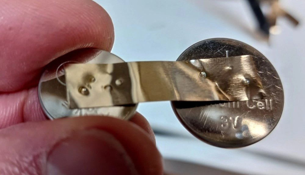
, by Clemens Valens Fix Battery Packs Like a Pro: Fnirsi SWM-10 Portable Spot Welder Review
In an era dominated by cordless tools, electric bikes, and various battery-powered devices, the ability to repair battery packs has become increasingly important. Spot welding,...
-
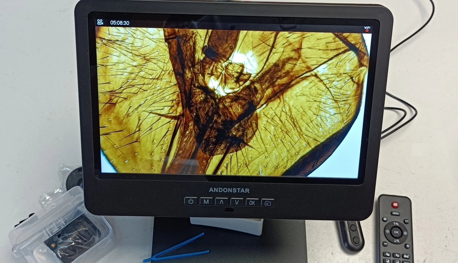
, by Clemens Valens Review: The Andonstar AD249S-M Digital Microscope Magnifies Up To 2040 Times
The Andonstar AD249S-M is a digital microscope with a 10” display and a magnification factor of up to 2040 times. It comes with three lenses,...

