Search results for "smart OR home OR internet OR of OR things OR kit OR for OR arduino"
-

Elektor Digital Internet of Things (E-book)
The Internet of Things (IoT) is a new concept in intelligent automation and intelligent monitoring using the Internet as the communications medium. The “Things” in IoT usually refer to devices that have unique identifiers and are connected to the Internet to exchange information with each other. Such devices usually have sensors and/or actuators that can be used to collect data about their environments and to monitor and control their environments. The collected data can be processed locally or it can be sent to centralized servers or to the cloud for remote storage and processing. For example, a small device at the size of a matchbox can be used to collect data about the temperature, relative humidity and the atmospheric pressure. This data can be sent and stored in the cloud. Anyone with a mobile device can then access and monitor this data at any time and from anywhere on Earth provided there is Internet connectivity. In addition, users can for example, adjust the central heating remotely using their mobile devices and accessing the cloud. This book is written for students, for practising engineers and for hobbyists who want to learn more about the building blocks of an IoT system and also learn how to setup an IoT system using these blocks. Chapter 1 is an introduction to the IoT systems. In Chapter 2, the basic concepts and possible IoT architectures are discussed. The important parts of any IoT system are the sensors and actuators and they are described briefly in Chapter 3. The devices in an IoT system usually communicate with each other and the important aspect of IoT communication is covered in Chapter 4. Chapter 5 proceeds with the features of some of the commonly used development kits. One of these, the Clicker 2 for PIC18FJ manufactured by mikroElektronika, can be used as a processor in IoT systems and its features are described in detail in Chapter 6. A popular microcontroller C language, mikroC Pro for PIC gets introduced in Chapter 7. Chapter 8 covers the use of a click board with the Clicker 2 for PIC18FJ development kit. Similarly, the use of a sensor click board is described as a project in Chapter 9, and an actuator board in Chapter 10. Chapters 11 and 12 cover Bluetooth and Wi-Fi technologies in microcontroller based systems, and the remaining chapters of the book demo the creation of a simple Wi-Fi based IoT system with cloud-based data storage. This book has been written with the assumption that the reader has taken a course on digital logic design and has been exposed to writing programs using at least one high-level programming language. Knowledge of the C programming language will be very useful. Also, familiarity with at least one member of the PIC series of microcontrollers (e.g. PIC16 or PIC18) will be an advantage. The knowledge of assembly language programming is not required because all the projects in the book are based on using the C language. If you are a total beginner in programming you can still access the e-book, but first you are advised to study introductory books on microcontrollers.
€ 34,95
Members € 27,96
-
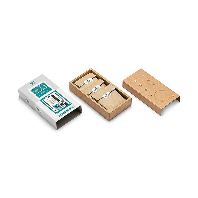
Arduino Arduino Make-Your-Uno Kit
Learn the basics of electronics by assembling manually your Arduino Uno, become familiar with soldering by mounting every single component, and then unleash your creativity with the only kit that becomes a synth! The Arduino Make-Your-Uno kit is really the best way to learn how to solder. And when you are done, the packaging allows you to build a synth and make your music. A kit with all the components to build your very own Arduino Uno and audio synthesizer shield. The Make-Your-Uno kit comes with a complete set of instructions in a dedicated content platform. This includes video material, a 3D interactive viewer for following detailed instructions, and how to program your board once it is finished. This kit contains: Arduino Make-Your-Uno 1x Make-Your-Uno PCB 1x USB C Serial adapter Board 7x Resistors 1k Ohm 2x Resistors 10k Ohm 2x Resistors 1M Ohm 1x Diode (1N4007) 1x 16 MHz Crystal 4x Yellow LEDs 1x Green LED 1x Push-Button 1x MOSFET 1x LDO (3.3 V) 1x LDO (5 V) 3x Ceramic capacitors (22pF) 3x Electrolytic capacitors (47uF) 7x Polyester capacitors (100nF) 1x Socket for ATMega 328p 2x I/O Connectors 1x Connector header 6 pins 1x Barrel jack connector 1x ATmega 328p Microcontroller Arduino Audio Synth 1x Audio Synth PCB 1x Resistor 100k Ohm 1x Resistor 10 Ohm 1x Audio amplifier (LM386) 1x Ceramic capacitors (47nF) 1x Electrolytic capacitors (47uF) 1x Electrolytic capacitors (220uF) 1x Polyester capacitor (100nF) 4x connectors pin header 6x potentiometer 10k Ohm with plastic knobs Spare parts 2x Electrolytic capacitors (47uF) 2x Polyester capacitor (100nF) 2x Ceramic capacitors (22pF) 1x Push-Button 1x Yellow LEDs 1x Green LED Mechanical parts 5x Spacers 12 mm 11x Spacers 6 mm 5x screw nuts 2x screws 12 mm
€ 79,95€ 31,98
Members identical
-
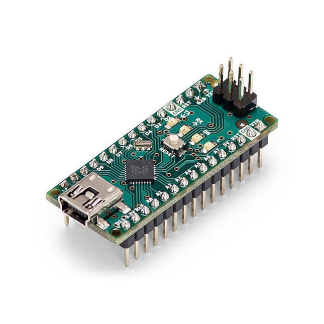
Arduino Arduino Nano
The Arduino Nano is a small, complete, and breadboard-friendly board based on the ATmega328 (Arduino Nano 3.x). It has more or less the same functionality of the Arduino Duemilanove but in a different package. It lacks only a DC power jack and works with a Mini-B USB cable instead of a standard one. Specifications Microcontroller ATmega328 Operating Voltage (logic level) 5 V Input Voltage (recommended) 7-12 V Input Voltage (limits) 6-20 V Digital I/O Pins 14 (of which 6 provide PWM output) Analog Input Pins 8 DC Current per I/O Pin 40 mA Flash Memory 16 KB (ATmega168) or 32 KB (ATmega328) of which 2 KB used by bootloader SRAM 1 KB (ATmega168) or 2 KB (ATmega328) EEPROM 512 bytes (ATmega168) or 1 KB (ATmega328) Clock Speed 16 MHz Dimensions 0.73 x 1.70' (18 x 45 mm) Power The Arduino Nano can be powered via the Mini-B USB connection, 6-20 V unregulated external power supply (pin 30), or 5 V regulated external power supply (pin 27). The power source is automatically selected to the highest voltage source. Memory The ATmega168 has 16 KB of flash memory for storing code (of which 2 KB is used for the bootloader), 1 KB of SRAM and 512 bytes of EEPROM The ATmega328 has 32 KB of flash memory for storing code, (also with 2 KB used for the bootloader), 2 KB of SRAM and 1 KB of EEPROM. Input and Output Each of the 14 digital pins on the Nano can be used as an input or output, using pinMode(), digitalWrite(), and digitalRead() functions. They operate at 5 V. Each pin can provide or receive a maximum of 40 mA and has an internal pull-up resistor (disconnected by default) of 20-50 kOhms. Communication The Arduino Nano has a number of facilities for communicating with a computer, another Arduino, or other microcontrollers. The ATmega168 and ATmega328 provide UART TTL (5V) serial communication, which is available on digital pins 0 (RX) and 1 (TX). An FTDI FT232RL on the board channels this serial communication over USB and the FTDI drivers (included with the Arduino software) provide a virtual com port to software on the computer. The Arduino software includes a serial monitor which allows simple textual data to be sent to and from the Arduino board. The RX and TX LEDs on the board will flash when data is being transmitted via the FTDI chip and USB connection to the computer (but not for serial communication on pins 0 and 1). A SoftwareSerial library allows for serial communication on any of the Nano's digital pins. Programming The Arduino Nano can be programmed with the Arduino software (download). The ATmega168 or ATmega328 on the Arduino Nano comes with a bootloader that allows you to upload new code to it without the use of an external hardware programmer. It communicates using the original STK500 protocol (reference, C header files). You can also bypass the bootloader and program the microcontroller through the ICSP (In-Circuit Serial Programming) header using Arduino ISP or similar; see these instructions for details. Automatic (Software) Reset Rather than requiring a physical press of the reset button before an upload, the Arduino Nano is designed in a way that allows it to be reset by software running on a connected computer. One of the hardware flow control lines (DTR) of theFT232RL is connected to the reset line of the ATmega168 or ATmega328 via a 100 nF capacitor. When this line is asserted (taken low), the reset line drops long enough to reset the chip. The Arduino software uses this capability to allow you to upload code by simply pressing the upload button in the Arduino environment. This means that the bootloader can have a shorter timeout, as the lowering of DTR can be well-coordinated with the start of the upload.
€ 22,95
Members € 20,66
-

Elektor Digital Home Automation Projects with Arduino (E-book)
Using the RFID Starter Kit An Arduino board has now become ‘the’ basic component in the maker community. No longer is an introduction to the world of microcontrollers the preserve of the expert. When it comes to expanding the capabilities of the basic Arduino board however, the developer is still largely on his own. If you really want to build some innovative projects it’s often necessary to get down to component level. This can present many beginners with major problems. That is exactly where this book begins. This book explains how a wide variety of practical projects can be built using items supplied in a single kit together with the Arduino board. This kit, called the 'RFID Starter Kit for Arduino' (SKU 17240) is not just limited to RFID applications but contains more than 30 components, devices and modules covering all areas of modern electronics. In addition to more simple components such as LEDs and resistors there are also complex and sophisticated modules that employ the latest technology such as: A humidity sensor A multicolor LED A large LED matrix with 64 points of light A 4-character 7-segment LED display An infra red remote-controller unit A complete LC-display module A servo A stepper motor and controller module A complete RFID reader module and security tag On top of that you will get to build precise digital thermometers, hygrometers, exposure meters and various alarm systems. There are also practical devices and applications such as a fully automatic rain sensor, a sound-controlled remote control system, a multifunctional weather station and so much more. All of the projects described can be built using the components supplied in the Elektor kit.
€ 29,95
Members € 23,96
-

Elektor Labs Elektor Arduino MultiCalculator
The Elektor MultiCalculator Kit is an Arduino-based multifunction calculator that goes beyond basic calculations. It offers 22 functions including light and temperature measurement, differential temperature analysis, and NEC IR remote control decoding. The Elektor MultiCalculator is a handy tool for use in your projects or for educational purposes. The kit features a Pro Mini module as the computing unit. The PCB is easy to assemble using through-hole components. The enclosure consists of 11 acrylic panels and mounting materials for easy assembly. Additionally, the device is equipped with a 16x2 alphanumeric LCD, 20 buttons, and temperature sensors. The Elektor MultiCalculator is programmable with the Arduino IDE through a 6-way PCB header. The available software is bilingual (English and Dutch). The calculator can be programmed with a programming adapter, and it is powered through USB-C. Modes of Operation Calculator 4-Ring Resistor Code 5-Ring Resistor Code Decimal to Hexadecimal and Character (ASCII) conversion Hexadecimal to Decimal and Character (ASCII) conversion Decimal to Binary and Character (ASCII) conversion Binary to Decimal and Hexadecimal conversion Hz, nF, capacitive reactance (XC) calculation Hz, µH, inductive reactance (XL) calculation Resistance calculation of two resistors connected in parallel Resistance calculation of two resistors connected in series Calculation of unknown parallel resistor Temperature measurement Differential temperature measurement T1&T2 and Delta (δ) Light measurement Stopwatch with lap time function Item counter NEC IR remote control decoding AWG conversion (American Wire Gauge) Rolling Dice Personalize startup message Temperature calibration Specifications Menu languages: English, Dutch Dimensions: 92 x 138 x 40 mm Build time: approx. 5 hours Included PCB and though-hole components Precut acrylic sheets with all mechanical parts Pro Mini microcontroller module (ATmega328/5 V/16 MHz) Programming adapter Waterproof temperature sensors USB-C cable Downloads Software
€ 49,95€ 39,95
Members identical
-

Elektor Classics The Arduino Collection (USB Stick)
This USB Stick contains more than 300 Arduino-related articles published in Elektor Magazine. The content includes both background articles and projects on the following topics: Software & hardware development: Tutorials on Arduino software development using Arduino IDE, Atmel Studio, Shields, and essential programming concepts. Learning: The Microcontroller Bootcamp offers a structured approach to programming embedded systems. Data acquisition & measurement: Projects such as a 16-bit data logger, lathe tachometer, and an AC grid analyzer for capturing and analyzing real-time signals. Wireless communication: Learn how to implement wireless networks, create an Android interface, and communicate effectively with microcontrollers. Robotics and automation: This covers the Arduino Nano Robot Controller, supporting boards for automation, and explores various Arduino shields to enhance functionality. Self-build projects: Unique projects such as laser projection, Numitron clock and thermometer, ELF receiver, Theremino, and touch LED interfaces highlight creative applications. Whether you're a beginner or an experienced maker, this collection is a valuable resource for learning, experimenting, and pushing the boundaries of Arduino technology.
€ 49,95€ 19,98
Members identical
-

Elektor Publishing Mastering the Arduino Uno R4
Programming and Projects for the Minima and WiFi Based on the low-cost 8-bit ATmega328P processor, the Arduino Uno R3 board is likely to score as the most popular Arduino family member, and this workhorse has been with us for many years. Eleven years later, the long-overdue successor, the Arduino Uno R4, was released. It is built around a 48 MHz, 32-bit Arm Cortex-M4 microcontroller and provides significantly expanded SRAM and Flash memory. Additionally, a higher-precision ADC and a new DAC are added to the design. The Uno R4 board also supports the CAN Bus with an interface. Two versions of the board are available: Uno R4 Minima, and Uno R4 WiFi. This book is about using these new boards to develop many different and interesting projects with just a handful of parts and external modules. All projects described in the book have been fully tested on the Uno R4 Minima or the Uno R4 WiFi board, as appropriate. The project topics include the reading, control, and driving of many components and modules in the kit as well as on the relevant Uno R4 board, including LEDs 7-segment displays (using timer interrupts) LCDs Sensors RFID Reader 4x4 Keypad Real-time clock (RTC) Joystick 8×8 LED matrix Motors DAC (Digital-to-analog converter) LED matrix WiFi connectivity Serial UART CAN bus Infrared controller and receiver Simulators … all in creative and educational ways with the project operation and associated software explained in great detail.
€ 39,95
Members € 35,96
-
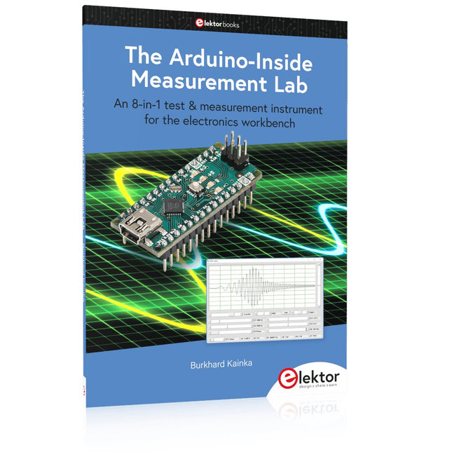
Elektor Publishing The Arduino-Inside Measurement Lab
An 8-in-1 test & measurement instrument for the electronics workbench A well-equipped electronics lab is crammed with power supplies, measuring devices, test equipment and signal generators. Wouldn‘t it be better to have one compact device for almost all tasks? Based on the Arduino, a PC interface is to be developed that’s as versatile as possible for measurement and control. It simply hangs on a USB cable and – depending on the software – forms the measuring head of a digital voltmeter or PC oscilloscope, a signal generator, an adjustable voltage source, a frequency counter, an ohmmeter, a capacitance meter, a characteristic curve recorder, and much more. The circuits and methods collected here are not only relevant for exactly these tasks in the "MSR" electronics lab, but many details can also be used within completely different contexts. Errata/Updates In the programs printed, all instances of “be()” should read: sei().
€ 34,95
Members € 31,46
-
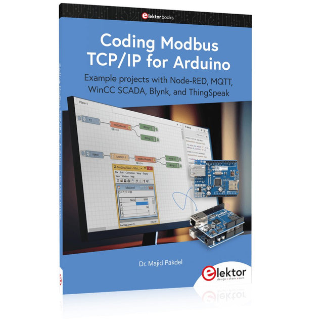
Elektor Publishing Coding Modbus TCP/IP for Arduino
Example projects with Node-RED, MQTT, WinCC SCADA, Blynk, and ThingSpeak This comprehensive guide unlocks the power of Modbus TCP/IP communication with Arduino. From the basics of the Modbus protocol right up to full implementation in Arduino projects, the book walks you through the complete process with lucid explanations and practical examples. Learn how to set up Modbus TCP/IP communication with Arduino for seamless data exchange between devices over a network. Explore different Modbus functions and master reading and writing registers to control your devices remotely. Create Modbus client and server applications to integrate into your Arduino projects, boosting their connectivity and automation level. With detailed code snippets and illustrations, this guide is perfect for beginners and experienced Arduino enthusiasts alike. Whether you‘re a hobbyist looking to expand your skills or a professional seeking to implement Modbus TCP/IP communication in your projects, this book provides all the knowledge you need to harness the full potential of Modbus with Arduino. Projects covered in the book: TCP/IP communication between two Arduino Uno boards Modbus TCP/IP communication within the Node-RED environment Combining Arduino, Node-RED, and Blynk IoT cloud Interfacing Modbus TCP/IP with WinCC SCADA to control sensors Using MQTT protocol with Ethernet/ESP8266 Connecting to ThingSpeak IoT cloud using Ethernet/ESP8266
€ 39,95
Members identical
-

Elektor Bundles Arduino Uno R4 WiFi (Bundle)
Book: Mastering the Arduino Uno R4 Based on the low-cost 8-bit ATmega328P processor, the Arduino Uno R3 board is likely to score as the most popular Arduino family member, and this workhorse has been with us for many years. Eleven years later, the long-overdue successor, the Arduino Uno R4, was released. It is built around a 48 MHz, 32-bit Arm Cortex-M4 microcontroller and provides significantly expanded SRAM and Flash memory. Additionally, a higher-precision ADC and a new DAC are added to the design. The Uno R4 board also supports the CAN Bus with an interface. Two versions of the board are available: Uno R4 Minima, and Uno R4 WiFi. This book is about using these new boards to develop many different and interesting projects with just a handful of parts and external modules. All projects described in the book have been fully tested on the Uno R4 Minima or the Uno R4 WiFi board, as appropriate. The project topics include the reading, control, and driving of many components and modules in the kit as well as on the relevant Uno R4 board, including LEDs 7-segment displays (using timer interrupts) LCDs Sensors RFID Reader 4x4 Keypad Real-time clock (RTC) Joystick 8×8 LED matrix Motors DAC (Digital-to-analog converter) LED matrix WiFi connectivity Serial UART CAN bus Infrared controller and receiver Simulators … all in creative and educational ways with the project operation and associated software explained in great detail. Arduino Uno R4 WiFi The Arduino Uno R4 is powered by the Renesas RA4M1 32-bit ARM Cortex-M4 processor, providing a significant boost in processing power, memory, and functionality. The WiFi version comes with an ESP32-S3 WiFi module in addition to the RA4M1, expanding creative opportunities for makers and engineers. The Arduino Uno R4 runs at 48 MHz, which provides a 3x increase over the popular Uno R3. Additionally, SRAM has been upgraded from 2 kB to 32 kB, and flash memory from 32 kB to 256 kB to support more complex projects. Responding to community feedback, the USB port is now USB-C, and the maximum power supply voltage has been raised to 24 V with an enhanced thermal design. The board includes a CAN bus and an SPI port, enabling users to reduce wiring and perform parallel tasks by connecting multiple shields. A 12-bit analog DAC is also provided on the board. Specifications Microcontroller Renesas RA4M1 (ARM Cortex-M4) USB USB-C Programming Port Pins Digital I/O Pins 14 Pins Analog input pins 6 DAC 1 RTC 1 PWM pins 6 Communication UART 1x I²C 1x SPI 1x Qwiic I²C connector 1x CAN 1x CAN Bus Power Circuit operating voltage 5 V Input voltage (VIN) 6-24 V DC Current per I/O Pin 8 mA Clock speed Main core 48 MHz Memory RA4M1 256 kB Flash, 32 kB RAM LED Matrix 12 x 8 (96 red LEDs) Dimensions 68.9 x 53.4 mm Downloads Datasheet Schematics This bundle contains: Book: Mastering the Arduino Uno R4 (normal price: €40) Arduino Uno R4 WiFi (normal price: €30)
€ 69,95€ 59,95
Members identical
-
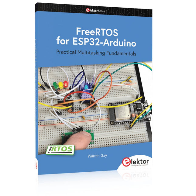
Elektor Publishing FreeRTOS for ESP32-Arduino
Practical Multitasking Fundamentals Programming embedded systems is difficult because of resource constraints and limited debugging facilities. Why develop your own Real-Time Operating System (RTOS) as well as your application when the proven FreeRTOS software is freely available? Why not start with a validated foundation? Every software developer knows that you must divide a difficult problem into smaller ones to conquer it. Using separate preemptive tasks and FreeRTOS communication mechanisms, a clean separation of functions is achieved within the entire application. This results in safe and maintainable designs. Practicing engineers and students alike can use this book and the ESP32 Arduino environment to wade into FreeRTOS concepts at a comfortable pace. The well-organized text enables you to master each concept before starting the next chapter. Practical breadboard experiments and schematics are included to bring the lessons home. Experience is the best teacher. Each chapter includes exercises to test your knowledge. The coverage of the FreeRTOS Application Programming Interface (API) is complete for the ESP32 Arduino environment. You can apply what you learn to other FreeRTOS environments, including Espressif’s ESP-IDF. The source code is available from GitHub. All of these resources put you in the driver’s seat when it is time to develop your next uber-cool ESP32 project. What you will learn: How preemptive scheduling works within FreeRTOS The Arduino startup “loopTask” Message queues FreeRTOS timers and the IDLE task The semaphore, mutex, and their differences The mailbox and its application Real-time task priorities and its effect Interrupt interaction and use with FreeRTOS Queue sets Notifying tasks with events Event groups Critical sections Task local storage The gatekeeper task
€ 44,95
Members € 40,46


-
, by Lobna Belarbi Must-Have Boards, Kits & Tools to Start Your Arduino Journey with Elektor
Whether you're a newcomer eager to explore the world of microcontrollers or an experienced maker seeking to expand your toolkit, Elektor offers a curated selection...
