The starter kit for Jetson Nano is one of the best kits for beginners to get started with Jetson Nano. This kit includes 32 GB MicroSD card, 20 W adapter, 2-pin jumper, camera, and micro-USB cable.
Features
32 GB High-performance MicroSD card
5 V 4 A power supply with 2.1 mm DC barrel connector
2-pin jumper
Raspberry Pi camera module V2
Micro-B To Type-A USB cable with DATA enabled
Features
Internal LNA amplifier and selectable attenuator
Low frequency support from 50KHz covering LF, MF, HF, VHF and UHF up to 960Mhz
New HELP and SET buttons to improve user interface and configuration selection with 2-clicks
Wide band coverage to all popular sub-1Ghz bands, including FM, TV and DTV, ISM, RFID, GSM, etc.
Ideal choice for HAM bands from 160meters to 33cm
Pocket size and light weight
Solid metal case
Spectrum Analyzer mode with Peak Max and Hold, Normal, Overwrite and Averaging modes
High capacity internal Lithium battery for 20hs+ of continuous run, rechargeable by USB
Multi-platform Windows/Linux/MacOS Open Source software and API libraries
Can be extended with internal Expansion Modules for additional band and functionality
Specifications
Frequency band: 0.05 MHz - 960 MHz
Frequency span: 0.1 MHz - 960 MHz
Internal selectable LNA 25 dB gain
Internal selectable Attenuator 30 dB
Graphics LCD 128 x 64 pixels, great visibility outdoors
Support included for Windows, Linux and MacOS X
Backlight for great visibility indoor
Internal Lithium Ion 1800mA/h rechargeable battery
Standard SMA 50 Ω connector
Wideband 144/433MHz dual band telescopic antenna included
UHF 400-900 MHz rubber duck articulated antenna included
Amplitude resolution: 0.5dBm
Dynamic range: -125 dBm to 10 dBm
Absolute Max input power: +30dBm
Average noise level (typical LNA): -125 dBm
Frequency stability and accuracy (typical): +-10 ppm
Amplitude stability and accuracy (typical): +-2d Bm
Frequency resolution: 1kHz
Resolution bandwidth (RBW): automatic 2.6 kHz to 600 kHz
Included
1x RF Explorer WSUB1G+ Spectrum Analyzer
1x Mini USB cable
1x Dual band 144/430MHz Telescopic antenna
1x UHF 400-900Mhz antenna
1x EVA case
You can use RF Explorer 3G Combo equally well outdoor and indoor, and you can also connect it to a PC for extra functionality using standard mini-USB 2.0 connector.
This model includes a WSUB1G baseline unit plus an RFEMWSUB3G Expansion Module conveniently assembled and tested. It comes with two SMA connectors and two antennas,a dual band telescopic 144 / 430 MHz antenna for all Sub-GHz frequencies and a whip helical antenna for 2.4 GHz band. Additional, specific band antennas may be needed to cover efficiently some of the frequencies supported.
The combination of these two models offer the wide band coverage of the WSUB3G module, together with the highest sensitivity and quick response of the WSUB1G model for the popular sub-1GHz frequencies.
Features
Pocket size and light weight
Solid aluminum metal case
Includes a transport EVA carry case for RF Explorer
Spectrum Analyzer mode with Peak Max and Hold, Normal, Overwrite and Averaging modes
Lifetime free firmware upgrades available, open to community requested features
High capacity Lipo for 16 hours+ of continuous run, rechargeable by USB
Windows PC client Open Source
Can be extended with internal Expansion Modules for additional band and functionality
Wide band coverage to all popular RF frequencies, starting at 15 MHz and going up to 2.7 GHz. This includes very interesting frequency areas such as 2 m HAM radio, all VHF and UHF, FM radio, GPS, WiFi and WiMax, Bluetooth, etc.
Firmware: RF Explorer 3G Combo is delivered with upgraded firmware v1.09. Note some of the features and operation accuracy will be improved in upcoming free firmware revisions.
Specifications
Battery
Lithium Cells / Batteries contained in equipment UN3481 - PI967
Frequency band
15-2700 MHz
Frequency span
112 KHz - 600 MHz
Graphics LCD
128 x 64 pixels, great visibility outdoors
PC Windows client
supports Windows XP/Vista/Win7 both 32 and 64bits
Backlight
for great indoor visibility
2 standard SMA 50 ohms connector,
one for Sub-GHz wideband Nagoya NA-773 telescopic antenna included and another 2.4 GHz one for 15-2700 MHz band with helical antenna included.
Amplitude resolution
0.5 dBm
Dynamic range
Left SMA port (WSUB1G)
-115 dBm to 0 dBm
Right SMA port (WSUB3G)
-110 dBm to -10 dBm
Absolute Max input power
Left SMA port (WSUB1G)
+5 dBm
Right SMA port (WSUB3G)
+30 dBm
Average noise level (typical)
-110 dBm
Frequency stability and accuracy (typical)
+-10 ppm
Amplitude stability and accuracy (typical)
+-6 dBm
Frequency resolution
1 KHz
Resolution bandwidth (RBW)
automatic 3 KHz to 600 KHz
Weight
185 g
Size
113 x 70 x 25 mm
Included
RF Explorer 3G Combo
Nagoya NA-773 wideband telescopic antenna
2.4 GHz band antenna
EVA Case
Documentation
For more info and to get started with your RF Explorer, visit the start page.
For questions and support, please visit https://support.rf-explorer.com
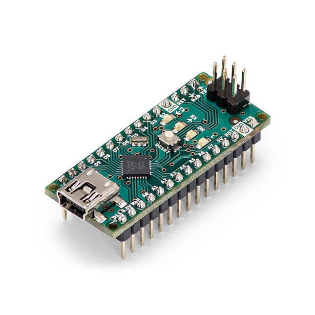
The Arduino Nano is a small, complete, and breadboard-friendly board based on the ATmega328 (Arduino Nano 3.x). It has more or less the same functionality of the Arduino Duemilanove but in a different package. It lacks only a DC power jack and works with a Mini-B USB cable instead of a standard one.
Specifications
Microcontroller
ATmega328
Operating Voltage (logic level)
5 V
Input Voltage (recommended)
7-12 V
Input Voltage (limits)
6-20 V
Digital I/O Pins
14 (of which 6 provide PWM output)
Analog Input Pins
8
DC Current per I/O Pin
40 mA
Flash Memory
16 KB (ATmega168) or 32 KB (ATmega328) of which 2 KB used by bootloader
SRAM
1 KB (ATmega168) or 2 KB (ATmega328)
EEPROM
512 bytes (ATmega168) or 1 KB (ATmega328)
Clock Speed
16 MHz
Dimensions
0.73 x 1.70' (18 x 45 mm)
Power
The Arduino Nano can be powered via the Mini-B USB connection, 6-20 V unregulated external power supply (pin 30), or 5 V regulated external power supply (pin 27). The power source is automatically selected to the highest voltage source.
Memory
The ATmega168 has 16 KB of flash memory for storing code (of which 2 KB is used for the bootloader), 1 KB of SRAM and 512 bytes of EEPROM
The ATmega328 has 32 KB of flash memory for storing code, (also with 2 KB used for the bootloader), 2 KB of SRAM and 1 KB of EEPROM.
Input and Output
Each of the 14 digital pins on the Nano can be used as an input or output, using pinMode(), digitalWrite(), and digitalRead() functions. They operate at 5 V.
Each pin can provide or receive a maximum of 40 mA and has an internal pull-up resistor (disconnected by default) of 20-50 kOhms.
Communication
The Arduino Nano has a number of facilities for communicating with a computer, another Arduino, or other microcontrollers.
The ATmega168 and ATmega328 provide UART TTL (5V) serial communication, which is available on digital pins 0 (RX) and 1 (TX). An FTDI FT232RL on the board channels this serial communication over USB and the FTDI drivers (included with the Arduino software) provide a virtual com port to software on the computer.
The Arduino software includes a serial monitor which allows simple textual data to be sent to and from the Arduino board. The RX and TX LEDs on the board will flash when data is being transmitted via the FTDI chip and USB connection to the computer (but not for serial communication on pins 0 and 1).
A SoftwareSerial library allows for serial communication on any of the Nano's digital pins.
Programming
The Arduino Nano can be programmed with the Arduino software (download).
The ATmega168 or ATmega328 on the Arduino Nano comes with a bootloader that allows you to upload new code to it without the use of an external hardware programmer. It communicates using the original STK500 protocol (reference, C header files).
You can also bypass the bootloader and program the microcontroller through the ICSP (In-Circuit Serial Programming) header using Arduino ISP or similar; see these instructions for details.
Automatic (Software) Reset
Rather than requiring a physical press of the reset button before an upload, the Arduino Nano is designed in a way that allows it to be reset by software running on a connected computer.
One of the hardware flow control lines (DTR) of theFT232RL is connected to the reset line of the ATmega168 or ATmega328 via a 100 nF capacitor. When this line is asserted (taken low), the reset line drops long enough to reset the chip.
The Arduino software uses this capability to allow you to upload code by simply pressing the upload button in the Arduino environment. This means that the bootloader can have a shorter timeout, as the lowering of DTR can be well-coordinated with the start of the upload.
Discover endless creativity with the Universal Maker Sensor Kit, designed for use with Raspberry Pi, Pico W, Arduino, and ESP32. This versatile kit offers compatibility across popular development platforms, including Arduino Uno R4 Minima/WiFi, Uno R3, Mega 2560, Raspberry Pi 5, 4, 3B+, 3B, Zero, Pico W, and ESP32.
Featuring over 35 sensors, actuators, and displays, it's perfect for projects ranging from environmental monitoring and smart home automation to robotics and interactive gaming. Step-by-step tutorials in C/C++, Python, and MicroPython guide beginners and experienced makers alike through 169 exciting projects.
Features
Wide Compatibility: Fully supports Arduino (Uno R3, Uno R4 Minima/WiFi, Mega 2560), Raspberry Pi (5, 4, 3B+, 3B, Zero, Pico W), and ESP32, enabling extensive flexibility across numerous development platforms. Includes instructions for building 169 projects.
Comprehensive Components: Features more than 35 sensors, actuators, and display modules suitable for diverse projects such as environmental monitoring, smart home automation, robotics, and interactive game controllers.
Detailed Tutorials: Provides clear, step-by-step tutorials covering Arduino, Raspberry Pi, Pico W, ESP32, and each included component. Tutorials are available in C/C++, Python, and MicroPython, catering effectively to both beginners and experienced makers.
Suitable for All Skill Levels: Offers structured projects designed to guide users seamlessly from beginner to advanced proficiency in electronics and programming, enhancing creativity and technical expertise.
Included
Breadboard
Button Module
Capacitive Soil Moisture Module
Flame Sensor Module
Gas/Smoke Sensor Module (MQ2)
Gyroscope & Accelerometer Module (MPU6050)
Hall Sensor Module
Infrared Speed Sensor Module
IR Obstacle Avoidance Sensor Module
Joystick Module
PCF8591 ADC DAC Converter Module
Photoresistor Module
PIR Motion Module (HC-SR501)
Potentiometer Module
Pulse Oximeter and Heart Rate Sensor Module (MAX30102)
Raindrop Detection Module
Real Time Clock Module (DS1302)
Rotary Encoder Module
Temperature Sensor Module (DS18B20)
Temperature and Humidity Sensor Module (DHT11)
Temperature, Humidity & Pressure Sensor (BMP280)
Time of Flight Micro-LIDAR Distance Sensor (VL53L0X)
Touch Sensor Module
Ultrasonic Sensor Module (HC-SR04)
Vibration Sensor Module (SW-420)
Water Level Sensor Module
I²C LCD 1602
OLED Display Module (SSD1306)
RGB LED Module
Traffic Light Module
5 V Relay Module
Centrifugal Pump
L9110 Motor Driver Module
Passive Buzzer Module
Servo Motor (SG90)
TT Motor
ESP8266 Module
JDY-31 Bluetooth Module
Power Supply Module
Documentation
Online Tutorial
The Elektor MultiCalculator Kit is an Arduino-based multifunction calculator that goes beyond basic calculations. It offers 22 functions including light and temperature measurement, differential temperature analysis, and NEC IR remote control decoding. The Elektor MultiCalculator is a handy tool for use in your projects or for educational purposes.
The kit features a Pro Mini module as the computing unit. The PCB is easy to assemble using through-hole components. The enclosure consists of 11 acrylic panels and mounting materials for easy assembly. Additionally, the device is equipped with a 16x2 alphanumeric LCD, 20 buttons, and temperature sensors.
The Elektor MultiCalculator is programmable with the Arduino IDE through a 6-way PCB header. The available software is bilingual (English and Dutch). The calculator can be programmed with a programming adapter, and it is powered through USB-C.
Modes of Operation
Calculator
4-Ring Resistor Code
5-Ring Resistor Code
Decimal to Hexadecimal and Character (ASCII) conversion
Hexadecimal to Decimal and Character (ASCII) conversion
Decimal to Binary and Character (ASCII) conversion
Binary to Decimal and Hexadecimal conversion
Hz, nF, capacitive reactance (XC) calculation
Hz, µH, inductive reactance (XL) calculation
Resistance calculation of two resistors connected in parallel
Resistance calculation of two resistors connected in series
Calculation of unknown parallel resistor
Temperature measurement
Differential temperature measurement T1&T2 and Delta (δ)
Light measurement
Stopwatch with lap time function
Item counter
NEC IR remote control decoding
AWG conversion (American Wire Gauge)
Rolling Dice
Personalize startup message
Temperature calibration
Specifications
Menu languages: English, Dutch
Dimensions: 92 x 138 x 40 mm
Build time: approx. 5 hours
Included
PCB and though-hole components
Precut acrylic sheets with all mechanical parts
Pro Mini microcontroller module (ATmega328/5 V/16 MHz)
Programming adapter
Waterproof temperature sensors
USB-C cable
Downloads
Software
This USB Stick contains more than 300 Arduino-related articles published in Elektor Magazine. The content includes both background articles and projects on the following topics:
Software & hardware development: Tutorials on Arduino software development using Arduino IDE, Atmel Studio, Shields, and essential programming concepts.
Learning: The Microcontroller Bootcamp offers a structured approach to programming embedded systems.
Data acquisition & measurement: Projects such as a 16-bit data logger, lathe tachometer, and an AC grid analyzer for capturing and analyzing real-time signals.
Wireless communication: Learn how to implement wireless networks, create an Android interface, and communicate effectively with microcontrollers.
Robotics and automation: This covers the Arduino Nano Robot Controller, supporting boards for automation, and explores various Arduino shields to enhance functionality.
Self-build projects: Unique projects such as laser projection, Numitron clock and thermometer, ELF receiver, Theremino, and touch LED interfaces highlight creative applications.
Whether you're a beginner or an experienced maker, this collection is a valuable resource for learning, experimenting, and pushing the boundaries of Arduino technology.
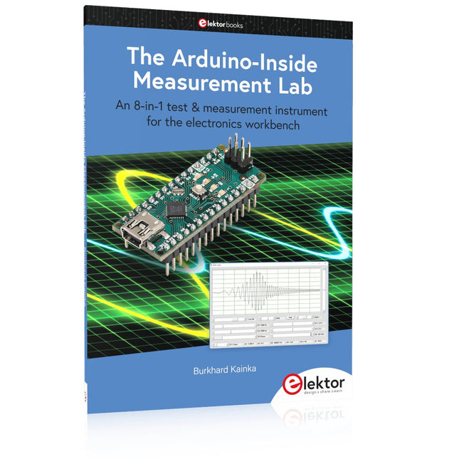
An 8-in-1 test & measurement instrument for the electronics workbench
A well-equipped electronics lab is crammed with power supplies, measuring devices, test equipment and signal generators. Wouldn‘t it be better to have one compact device for almost all tasks? Based on the Arduino, a PC interface is to be developed that’s as versatile as possible for measurement and control. It simply hangs on a USB cable and – depending on the software – forms the measuring head of a digital voltmeter or PC oscilloscope, a signal generator, an adjustable voltage source, a frequency counter, an ohmmeter, a capacitance meter, a characteristic curve recorder, and much more.
The circuits and methods collected here are not only relevant for exactly these tasks in the "MSR" electronics lab, but many details can also be used within completely different contexts.
Errata/Updates
In the programs printed, all instances of “be()” should read: sei().
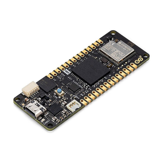
The Portenta C33 is a powerful System-on-Module designed for low-cost Internet of Things (IoT) applications. Based on the R7FA6M5BH2CBG microcontroller from Renesas, this board shares the same form factor as the Portenta H7 and it is backward compatible with it, making it fully compatible with all Portenta family shields and carriers through its high-density connectors.
As a low-cost device, the Portenta C33 is an excellent choice for developers looking to create IoT devices and applications on a budget. Whether you're building a smart home device or a connected industrial sensor, the Portenta C33 provides the processing power and connectivity options you need to get the job done.
Quickly deploying AI-powered projects becomes quick and easy with Portenta C33, by leveraging a vast array of ready-to-use software libraries and Arduino sketches available, as well as widgets that display data in real time on Arduino IoT Cloud-based dashboards.
Features
Ideal for low-cost IoT applications with Wi-Fi/Bluetooth LE connectivity
Supports MicroPython and other high-level programming languages
Offers industrial-grade security at the hardware level and secure OTA firmware updates
Leverages ready-to-use software libraries and Arduino sketches
Perfect to monitor and display real-time data on Arduino IoT Cloud widget-based dashboards
Compatible with Arduino Portenta and MKR families
Features castellated pins for automatic assembly lines
Cost Effective Performance
Reliable, secure and with computational power worthy of its range, Portenta C33 was designed to provide big and small companies in every field with the opportunity to access IoT and benefit from higher efficiency levels and automation.
Applications
Portenta C33 brings more applications than ever within users’ reach, from enabling quick plug-and-play prototyping to providing a cost-effective solution for industrial-scale projects.
Industrial IoT gateway
Machine monitoring to track OEE/OPE
Inline quality control and assurance
Energy consumption monitoring
Appliances control system
Ready-to-use IoT prototyping solution
Specifications
Microcontroller
Renesas R7FA6M5BH2CBG ARM Cortex-M33:
ARM Cortex-M33 core up to 200 MHz
512 kB onboard SRAM
2 MB onboard Flash
Arm TrustZone
Secure Crypto Engine 9
External Memories
16 MB QSPI Flash
USB-C
USB-C High Speed
Connectivity
100 MB Ethernet interface (PHY)
Wi-Fi
Bluetooth Low Energy
Interfaces
CAN
SD Card
ADC
GPIO
SPI
I²S
I²C
JTAG/SWD
Security
NXP SE050C2 Secure Element
Operating Temperatures
-40 to +85°C (-40 to 185°F)
Dimensions
66,04 x 25,40 mm
Downloads
Datasheet
Schematics
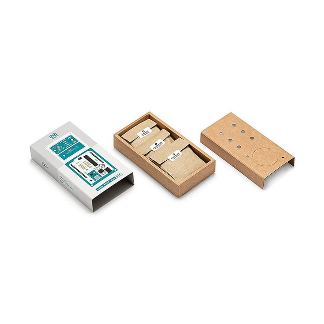
Learn the basics of electronics by assembling manually your Arduino Uno, become familiar with soldering by mounting every single component, and then unleash your creativity with the only kit that becomes a synth!
The Arduino Make-Your-Uno kit is really the best way to learn how to solder. And when you are done, the packaging allows you to build a synth and make your music.
A kit with all the components to build your very own Arduino Uno and audio synthesizer shield.
The Make-Your-Uno kit comes with a complete set of instructions in a dedicated content platform. This includes video material, a 3D interactive viewer for following detailed instructions, and how to program your board once it is finished.
This kit contains:
Arduino Make-Your-Uno
1x Make-Your-Uno PCB
1x USB C Serial adapter Board
7x Resistors 1k Ohm
2x Resistors 10k Ohm
2x Resistors 1M Ohm
1x Diode (1N4007)
1x 16 MHz Crystal
4x Yellow LEDs
1x Green LED
1x Push-Button
1x MOSFET
1x LDO (3.3 V)
1x LDO (5 V)
3x Ceramic capacitors (22pF)
3x Electrolytic capacitors (47uF)
7x Polyester capacitors (100nF)
1x Socket for ATMega 328p
2x I/O Connectors
1x Connector header 6 pins
1x Barrel jack connector
1x ATmega 328p Microcontroller
Arduino Audio Synth
1x Audio Synth PCB
1x Resistor 100k Ohm
1x Resistor 10 Ohm
1x Audio amplifier (LM386)
1x Ceramic capacitors (47nF)
1x Electrolytic capacitors (47uF)
1x Electrolytic capacitors (220uF)
1x Polyester capacitor (100nF)
4x connectors pin header
6x potentiometer 10k Ohm with plastic knobs
Spare parts
2x Electrolytic capacitors (47uF)
2x Polyester capacitor (100nF)
2x Ceramic capacitors (22pF)
1x Push-Button
1x Yellow LEDs
1x Green LED
Mechanical parts
5x Spacers 12 mm
11x Spacers 6 mm
5x screw nuts
2x screws 12 mm
Example projects with Node-RED, MQTT, WinCC SCADA, Blynk, and ThingSpeak
This comprehensive guide unlocks the power of Modbus TCP/IP communication with Arduino. From the basics of the Modbus protocol right up to full implementation in Arduino projects, the book walks you through the complete process with lucid explanations and practical examples.
Learn how to set up Modbus TCP/IP communication with Arduino for seamless data exchange between devices over a network. Explore different Modbus functions and master reading and writing registers to control your devices remotely. Create Modbus client and server applications to integrate into your Arduino projects, boosting their connectivity and automation level.
With detailed code snippets and illustrations, this guide is perfect for beginners and experienced Arduino enthusiasts alike. Whether you‘re a hobbyist looking to expand your skills or a professional seeking to implement Modbus TCP/IP communication in your projects, this book provides all the knowledge you need to harness the full potential of Modbus with Arduino.
Projects covered in the book:
TCP/IP communication between two Arduino Uno boards
Modbus TCP/IP communication within the Node-RED environment
Combining Arduino, Node-RED, and Blynk IoT cloud
Interfacing Modbus TCP/IP with WinCC SCADA to control sensors
Using MQTT protocol with Ethernet/ESP8266
Connecting to ThingSpeak IoT cloud using Ethernet/ESP8266
Practical Multitasking Fundamentals
Programming embedded systems is difficult because of resource constraints and limited debugging facilities. Why develop your own Real-Time Operating System (RTOS) as well as your application when the proven FreeRTOS software is freely available? Why not start with a validated foundation?
Every software developer knows that you must divide a difficult problem into smaller ones to conquer it. Using separate preemptive tasks and FreeRTOS communication mechanisms, a clean separation of functions is achieved within the entire application. This results in safe and maintainable designs.
Practicing engineers and students alike can use this book and the ESP32 Arduino environment to wade into FreeRTOS concepts at a comfortable pace. The well-organized text enables you to master each concept before starting the next chapter. Practical breadboard experiments and schematics are included to bring the lessons home. Experience is the best teacher.
Each chapter includes exercises to test your knowledge. The coverage of the FreeRTOS Application Programming Interface (API) is complete for the ESP32 Arduino environment. You can apply what you learn to other FreeRTOS environments, including Espressif’s ESP-IDF. The source code is available from GitHub. All of these resources put you in the driver’s seat when it is time to develop your next uber-cool ESP32 project.
What you will learn:
How preemptive scheduling works within FreeRTOS
The Arduino startup “loopTask”
Message queues
FreeRTOS timers and the IDLE task
The semaphore, mutex, and their differences
The mailbox and its application
Real-time task priorities and its effect
Interrupt interaction and use with FreeRTOS
Queue sets
Notifying tasks with events
Event groups
Critical sections
Task local storage
The gatekeeper task