The SparkFun GPS-RTK2 raises the bar for high-precision GPS and is the latest in a line of powerful RTK boards featuring the ZED-F9P module from u-blox. The ZED-F9P is a top-of-the-line module for high accuracy GNSS and GPS location solutions, including RTK capable of 10 mm, three-dimensional accuracy. With this board, you will be able to know where your (or any object's) X, Y, and Z location is within roughly the width of your fingernail! The ZED-F9P is unique in that it is capable of both rover and base station operations. Utilizing our handy Qwiic system, no soldering is required to connect it to the rest of your system. However, we still have broken out 0.1"-spaced pins if you prefer to use a breadboard.
We've even included a rechargeable backup battery to keep the latest module configuration and satellite data available for up to two weeks. This battery helps 'warm-start' the module decreasing the time-to-first-fix dramatically. This module features a survey-in mode allowing the module to become a base station and produce RTCM 3.x correction data.
The number of configuration options of the ZED-F9P is incredible! Geofencing, variable I²C address, variable update rates, even the high precision RTK solution can be increased to 20 Hz. The GPS-RTK2 even has five communications ports which are all active simultaneously: USB-C (which enumerates as a COM port), UART1 (with 3.3 V TTL), UART2 for RTCM reception (with 3.3V TTL), I²C (via the two Qwiic connectors or broken out pins), and SPI.
Sparkfun has also written an extensive Arduino library for u-blox modules to easily read and control the GPS-RTK2 over the Qwiic Connect System. Leave NMEA behind! Start using a much lighter weight binary interface and give your microcontroller (and its one serial port) a break. The SparkFun Arduino library shows how to read latitude, longitude, even heading and speed over I²C without the need for constant serial polling.
Features
Concurrent reception of GPS, GLONASS, Galileo and BeiDou
Receives both L1C/A and L2C bands
Voltage: 5 V or 3.3 V, but all logic is 3.3 V
Current: 68 mA - 130 mA (varies with constellations and tracking state)
Time to First Fix: 25 s (cold), 2 s (hot)
Max Navigation Rate:
PVT (basic location over UBX binary protocol) - 25 Hz
RTK - 20 Hz
Raw - 25 Hz
Horizontal Position Accuracy:
2.5 m without RTK
0.010 m with RTK
Max Altitude: 50k m
Max Velocity: 500 m/s
2x Qwiic Connectors
Dimensions: 43.5 x 43.2 mm
Weight: 6.8 g
The CubeCell series is designed primarily for LoRa/LoRaWAN node applications.
Built on the ASR605x platform (ASR6501, ASR6502), these chips integrate the PSoC 4000 series MCU (ARM Cortex-M0+ Core) with the SX1262 module. The CubeCell series offers seamless Arduino compatibility, stable LoRaWAN protocol operation, and straightforward connectivity with lithium batteries and solar panels.
The HTCC-AB02S is a developer-friendly board with an integrated AIR530Z GPS module, ideal for quickly testing and validating communication solutions.
Features
Arduino compatible
Based on ASR605x (ASR6501, ASR6502), those chips are already integrated the PSoC 4000 series MCU (ARM Cortex M0+ Core) and SX1262
LoRaWAN 1.0.2 support
Ultra low power design, 21 uA in deep sleep
Onboard SH1.25-2 battery interface, integrated lithium battery management system (charge and discharge management, overcharge protection, battery power detection, USB/battery power automatic switching)
Good impendence matching and long communication distance
Onboard solar energy management system, can directly connect with a 5.5~7 V solar panel
Micro USB interface with complete ESD protection, short circuit protection, RF shielding, and other protection measures
Integrated CP2102 USB to serial port chip, convenient for program downloading, debugging information printing
Onboard 0.96-inch 128x64 dot matrix OLED display, which can be used to display debugging information, battery power, and other information
Using Air530 GPS module with GPS/Beidou Dual-mode position system support
Specifications
Main Chip
ASR6502 (48 MHz ARM Cortex-M0+ MCU)
LoRa Chipset
SX1262
Frequency
863~870 MHz
Max. TX Power
22 ±1 dBm
Max. Receiving Sensitivity
−135 dBm
Hardware Resource
2x UART1x SPI2x I²C1x SWD3x 12-bit ADC input8-channel DMA engine16x GPIO
Memory
128 Kb FLASH16 Kb SRAM
Power consumption
Deep sleep 21 uA
Interfaces
1x Micro USB1x LoRa Antenna (IPEX)2x (15x 2.54 Pin header) + 3x (2x 2.54 Pin header)
Battery
3.7 V lithium battery (power supply and charging)
Solar Energy
VS pin can be connected to 5.5~7 V solar panel
USB to Serial Chip
CP2102
Display
0.96" OLED (128 x 64)
Operating temperature
−20~70°C
Dimensions
55.9 x 27.9 x 9.5 mm
Included
1x CubeCell HTCC-AB02S Development Board
1x Antenna
1x 2x SH1.25 battery connector
Downloads
Datasheet
Schematic
GPS module (Manual)
Quick start
GitHub
Pico Breakout Garden Base sits underneath your Pico and lets you connect up to six of our extensive selection of Pimoroni breakouts to it. Whether it's environmental sensors so you can keep track of the temperature and humidity in your office, a whole host of little screens for important notifications and readouts, and, of course, LEDs. Scroll down for a list of breakouts that are currently compatible with our C++/MicroPython libraries!As well as a labelled landing area for your Pico, there's also a full set of broken out Pico connections, in case you need to attach even more sensors, wires, and circuitry. We've thrown in some rubber feet to keep the base nice and stable and to stop it from scratching your desk, or there are M2.5 mounting holes at the corners so that you can bolt it onto a solid surface if you prefer.The six sturdy black slots are edge connectors that connect the breakouts to the pins on your Pico. There's two slots for SPI breakouts, and four slots for I²C breakouts. Because I²C is a bus, you can use multiple I²C devices at the same time, providing they don't have the same I²C address (we've made sure that all of our breakouts have different addresses, and we print them on the back of the breakouts so they're easy to find).As well as being a handy way to add functionality to your Pico, Breakout Garden is also very useful for prototyping projects without the need for complicated wiring, soldering, or breadboards, and you can grow or change up your setup at any time.Features
Six sturdy edge-connector slots for breakouts
4x I²C slots (5 pins)
2x SPI slot (7 pins)
Landing area with female headers for Raspberry Pi Pico
0.1” pitch, 5 or 7 pin connectors
Broken-out pins
Reverse polarity protection (built into breakouts)
99% assembled – just need to stick on the feet!
Compatible with Raspberry Pi Pico
Thanks to its six sturdy slots, Breakout Garden enables the users to simply plug and play with various tiny breakout board.
Just insert one or more boards into the slots in the Breakout Garden HAT and you’re ready to go. The mini breakouts feel secure enough in the edge-connector slots and are very unlikely to fall out.
There are a number of useful pins along the top of Breakout Garden, which lets you connect other devices and integrate them into your project.
You shouldn't be worried if you insert a board the wrong way thanks to provided reverse polarity protection. It doesn't matter which slot you use for each breakout either, because the I²C address of the breakout will be recognised by the software and it'll detect them correctly in case you move them around.
Features
Six sturdy edge-connector slots for Pimoroni breakouts
0.1” pitch, 5 pin connectors
Broken-out pins (1 × 10 strip of male header included)
Standoffs (M2.5, 10 mm height) included to hold your Breakout Garden securely
Reverse polarity protection (built into breakouts)
HAT format board
Compatible with Raspberry Pi 3 B+, 3, 2, B+, A+, Zero, and Zero W
It's suggested using the included standoffs to attache Breakout Garden to your Raspberry Pi.
Software
Breakout Garden doesn't require any software of its own, but each breakout you use will need a Python library. On the Breakout Garden GitHub page you'll find an automatic installer, which will install the appropriate software for a given breakout. There are also some examples that show you what else you can do with Breakout Garden.
The MLX90640 SparkFun IR Array Breakout features a 32×24 array of thermopile sensors generating, in essence, a low resolution thermal imaging camera. With this breakout you can observe surface temperatures from a decent distance away with an accuracy of ±1.5°C (best case). This board communicates via I²C using the Qwiic system developed by Sparkfun, which makes it easier to operate the breakout. However, there are still 0.1'-spaced pins in case you favour using a breadboard.
The SparkFun Qwiic connect system is an ecosystem of I²C sensors, actuators, shields and cables that make prototyping faster and helps you avoid errors. All Qwiic-enabled boards use a common 1 mm pitch, 4-pin JST connector. This reduces the amount of required PCB space, and polarized connections help you connect everything correctly.
This specific IR Array Breakout provides a 110°×75° field of view with a temperature measurement range of -40~300°C. The MLX90640 IR Array has pull up resistors attached to the I²C bus; both can be removed by cutting the traces on the corresponding jumpers on the back of the board. Please be aware that the MLX90640 requires complex calculations by the host platform so a regular Arduino Uno (or equivalent) doesn't have enough RAM or flash to complete the complex computations required to turn the raw pixel data into temperature data. You will need a microcontroller with 20,000 bytes or more of RAM.
Specifications
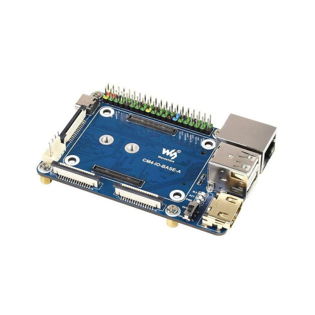
CM4 socket
Suitable for all variants of Compute Module 4
Networking
Gigabit Ethernet RJ45 connectorM.2 M KEY, supports communication modules or NVME SSD
Connector
Raspberry Pi 40-PIN GPIO header
USB
2x USB 2.0 Type A2x USB 2.0 via FFC connector
Display
MIPI DSI display port (15-pin 1.0 mm FPC connector)
Camera
2x MIPI CSI-2 camera port (15-pin 1.0 mm FPC connector)
Video
2x HDMI port (including one port via FFC connector), supports 4K 30fps output
RTC
N/A
Storage
MicroSD card socket for Compute Module 4 Lite (without eMMC) variants
Fan header
No fan control, 5 V
Power input
5 V
Dimensions
85 x 56 mm
Included
1x CM4-IO-BASE-A
1x SSD mounting screw
Downloads
Wiki
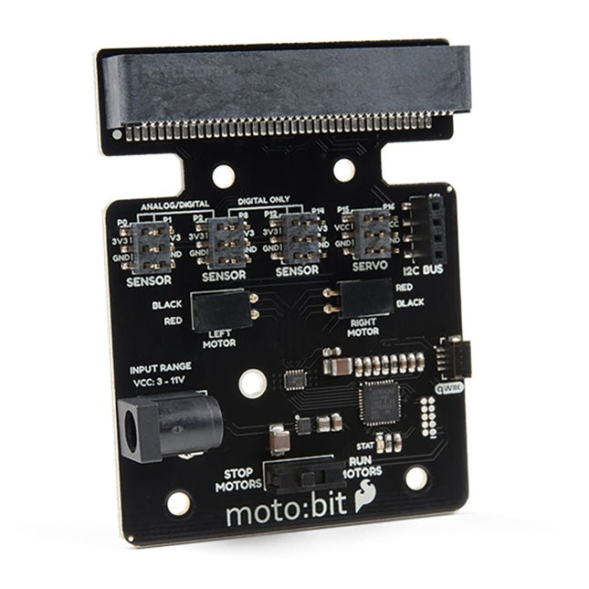
Onboard each moto:bit are multiple I/O pins, as well as a vertical Qwiic connector, capable of hooking up servos, sensors and other circuits. At the flip of the switch, you can get your micro:bit moving! The moto:bit connects to the micro:bit via an updated SMD, edge connector at the top of the board, making setup easy. This creates a handy way to swap out micro:bits for programming while still providing reliable connections to all of the different pins on the micro:bit. We have also included a basic barrel jack on the moto:bit that is capable of providing power to anything you connect to the carrier board. Features More reliable Edge connector for easy use with the micro:bit Full H-Bridge for control of two motors Control servo motors Vertical Qwiic Connector I²C port for extending functionality Power and battery management onboard for the micro:bit
Functionality, structure and handling of a power module
For readers with first steps in power management the “Abc of Power Modules” contains the basic principles necessary for the selection and use of a power module. The book describes the technical relationships and parameters related to power modules and the basis for calculation and measurement techniques.
Contents
Basics
This chapter describes the need of a DC/DC voltage converter and its basic functionality. Furthermore, various possibilities for realizing a voltage regulator are presented and the essential advantages of a power module are mentioned.
Circuit topologies
Circuit concepts, buck and boost topologies very frequently used with power modules are explained in detail and further circuit topologies are introduced.
Technology, construction and regulation technology
The mechanical construction of a power module is presented, which has a significant influence on EMC and thermal performance. Furthermore, control methods are explained and circuit design tips are provided in this chapter.
Measuring methods
Meaningful measurement results are absolutely necessary to assess a power module. The relevant measurement points and measurement methods are described in this chapter.
Handling
The aspects of storage and handling of power modules are explained, as well as their manufacturing and soldering processes.
Selection of a power modules
Important parameters and criteria for the optimal selection of a power module are presented in this section.
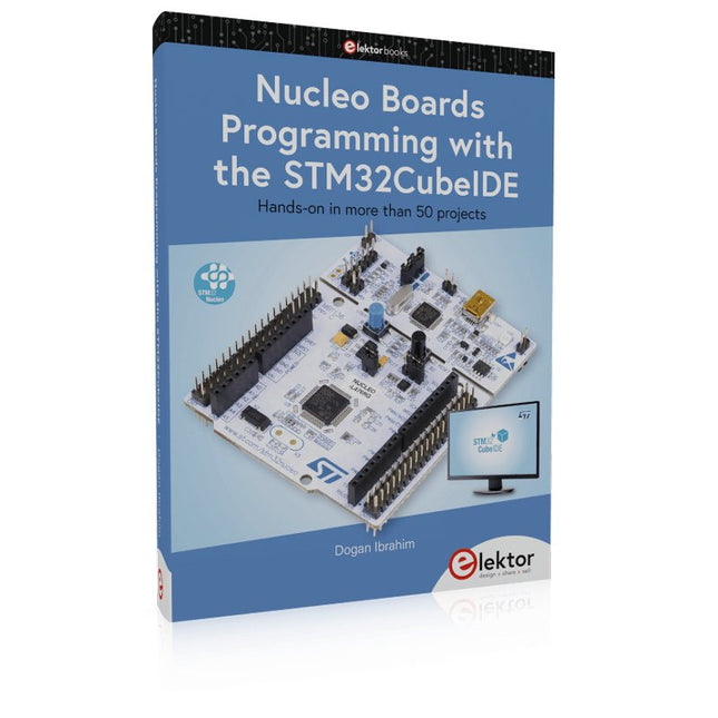
Hands-on in more than 50 projects
STM32 Nucleo family of processors are manufactured by STMicroelectronics. These are low-cost ARM microcontroller development boards. This book is about developing projects using the popular STM32CubeIDE software with the Nucleo-L476RG development board. In the early Chapters of the book the architecture of the Nucleo family is briefly described.
The book covers many projects using most features of the Nucleo-L476RG development board where the full software listings for the STM32CubeIDE are given for each project together with extensive descriptions. The projects range from simple flashing LEDs to more complex projects using modules, devices, and libraries such as GPIO, ADC, DAC, I²C, SPI, LCD, DMA, analogue inputs, power management, X-CUBE-MEMS1 library, DEBUGGING, and others. In addition, several projects are given using the popular Nucleo Expansion Boards. These Expansion Boards plug on top of the Nucleo development boards and provide sensors, relays, accelerometers, gyroscopes, Wi-Fi, and many others. Using an expansion board together with the X-CUBE-MEMS1 library simplifies the task of project development considerably.
All the projects in the book have been tested and are working. The following sub-headings are given for each project: Project Title, Description, Aim, Block Diagram, Circuit Diagram, and Program Listing for the STM32CubeIDE.
In this book you will learn about
STM32 microcontroller architecture;
the Nucleo-L476RG development board in projects using the STM32CubeIDE integrated software development tool;
external and internal interrupts and DMA;
DEBUG, a program developed using the STM32CubeIDE;
the MCU in Sleep, Stop, and in Standby modes;
Nucleo Expansion Boards with the Nucleo development boards.
What you need
a PC with Internet connection and a USB port;
STM32CubeIDE software (available at STMicroelectronics website free of charge)
the project source files, available from the book’s webpage hosted by Elektor;
Nucleo-L476RG development board;
simple electronic devices such as LEDs, temperature sensor, I²C and SPI chips, and a few more;
Nucleo Expansion Boards (optional).
The LuckFox Pico Ultra is a compact single-board computer (SBC) powered by the Rockchip RV1106G3 chipset, designed for AI processing, multimedia, and low-power embedded applications.
It comes equipped with a built-in 1 TOPS NPU, making it ideal for edge AI workloads. With 256 MB RAM, 8 GB onboard eMMC storage, integrated WiFi, and support for the LuckFox PoE module, the board delivers both performance and versatility across a wide range of use cases.
Running Linux, the LuckFox Pico Ultra supports a variety of interfaces – including MIPI CSI, RGB LCD, GPIO, UART, SPI, I²C, and USB – providing a simple and efficient development platform for applications in smart home, industrial control, and IoT.
Specifications
Chip
Rockchip RV1106G3
Processor
Cortex-A7 1.2 GHz
Neural Network Processor (NPU)
1 TOPS, supports int4, int8, int16
Image Processor (ISP)
Max input 5M @30fps
Memory
256 MB DDR3L
WiFi + Bluetooth
2.4GHz WiFi-6 Bluetooth 5.2/BLE
Camera Interface
MIPI CSI 2-lane
DPI Interface
RGB666
PoE Interface
IEEE 802.3af PoE
Speaker interface
MX1.25 mm
USB
USB 2.0 Host/Device
GPIO
30 GPIO pins
Ethernet
10/100M Ethernet controller and embedded PHY
Default Storage Medium
eMMC (8 GB)
Included
1x LuckFox Pico Ultra W
1x LuckFox PoE module
1x IPX 2.4G 2 db antenna
1x USB-A to USB-C cable
1x Screws pack
Downloads
Wiki
The FRDM-MCXN947 is a compact and versatile development board designed for rapid prototyping with MCX N94 and N54 microcontrollers. It features industry-standard headers for easy access to the MCU's I/Os, integrated open-standard serial interfaces, external flash memory, and an onboard MCU-Link debugger.
Specifications
Microcontroller
MCX-N947 Dual Arm Cortex-M33 cores @ 150 MHz each with optimized performance efficiency, up to 2 MB dual-bank flash with optional full ECC RAM, External flash
Accelerators: Neural Processing Unit, PowerQuad, Smart DMA, etc.
Memory Expansion
*DNP Micro SD card socket
Connectivity
Ethernet Phy and connector
HS USB-C connectors
SPI/I²C/UART connector (PMOD/mikroBUS, DNP)
WiFi connector (PMOD/mikroBUS, DNP)
CAN-FD transceiver
Debug
On-board MCU-Link debugger with CMSIS-DAP
JTAG/SWD connector
Sensor
P3T1755 I³C/I²C Temp Sensor, Touch Pad
Expansion Options
Arduino Header (with FRDM expansion rows)
FRDM Header
FlexIO/LCD Header
SmartDMA/Camera Header
Pmod *DNP
mikroBUS
User Interface
RGB user LED, plus Reset, ISP, Wakeup buttons
Included
1x FRDM-MCXN947 Development Board
1x USB-C Cable
1x Quick Start Guide
Downloads
Datasheet
Block diagram
The Power Delivery Board uses a standalone controller to negotiate with the power adapters and switch to a higher voltage other than just 5V. This uses the same power adapter for different projects rather than relying on multiple power adapters to provide different output; it can deliver the board as part of SparkFun’s Qwiic connect system, so you won’t have to do any soldering to figure out how things are oriented.
The SparkFun Power Delivery Board takes advantage of the power delivery standard using a standalone controller from STMicroelectronics, the STUSB4500. The STUSB4500 is a USB power delivery controller that addresses sink devices. It implements a proprietary algorithm to negotiate a power delivery contract with a source (i.e. a power delivery wall wart or power adapter) without the need for an external microcontroller. However, you will need a microcontroller to configure the board. PDO profiles are configured in an integrated non-volatile memory. The controller does all the heavy lifting of power negotiation and provides an easy way to configure over I²C.
To configure the board, you will need an I²C bus. The Qwiic system makes it easy to connect the Power Delivery board to a microcontroller. Depending on your application, you can also connect to the I²C bus via the plated through SDA and SCL holes.
Features
Input and output voltage range of 5-20V
Output current up to 5A
Three configurable power delivery profiles
Auto-run Type-C™ and USB PD sink controller
Certified USB Type-C™ rev 1.2 and USB PD rev 2.0 (TID #1000133)
Integrated VBUS voltage monitoring
Integrated VBUS switch gate drivers (PMOS)