Search results for "elektor OR circuit OR special OR 2025 OR fr"
-

Ynvisible Ynvisible Segment E-Paper Display Kit
The Ynvisible Segment E-Paper Displays are thin & flexible, sunlight readable, very easy to operate, and that they are the most energy-efficient display technology on the market for most applications. Get started today! Evaluate the ultra-low-power, thin and flexible Segment E-Paper Displays. The kit contains display designs and includes a manual display driver as well as a display driver with I²C interface. Display parameters White Reflectance 40% Contrast Ratio (Yb/Yd) 1:3 Angle Dependency No, lambertian Thickness 300 µm Graphical layout Segments Segment dimensions 1-100 mm Response time 100-1000 ms Power parameters Driving voltage 1.5 V Driving method Direct drive Energy consumption 1 mJ/cm^2 Pulse energy 0.25 mJ/cm^2 Image retention w/o power 1-5 minutes Operating conditions -20°C - +60°C Activations/Cycles 1.000.000 Included Ynvisible Segment Displays (Segmented e-paper displays with different layouts, shapes, and symbols, suitable for testing and evaluation.) 3 single-digit display 1 double-digit display 5 single-segment/icon displays 4 progress bars (7-segment and 3-segment) Manual Display Clicker (Manual display controller for ON/OFF operations) Display Driver and Software Library (Dedicated display driver with I²C communication interface. Compatible with Arduino and other easy-to-use development boards.) Flexible Display Adapter (For convenient connection of the flexible displays on a plastic substrate to rigid electronics (such as development boards), using a FFC/FPC connector.) Downloads Datasheet Guide & Instructions
-

Arduino Arduino Pro Portenta H7 Lite
Portenta H7 Lite allows you to build your next smart project. Ever wanted an automated house? Or a smart garden? Well, now it’s easy with the Arduino IoT Cloud compatible boards. It means: you can connect devices, visualize data, control and share your projects from anywhere in the world. The Arduino Pro Portenta H7 Lite is very similar to the Portenta H7, that simultaneously can run high level code along with real time tasks thanks to its two processors. It is, for example, possible to execute Arduino compiled code along with MicroPython one and have both cores to communicate with one another. However, the H7 Lite is a low-cost board with H7 functionalities that can be configured to specific use cases. Features Dual Core – Two best-in-class processors in one, running parallel tasks AI on the edge – So powerful it can run AI state machines Customization – The board is highly customizable in volumes High-level programming language support (Micropython) The Portenta H7 Lite offers twofold functionality: it can run either like any other embedded microcontroller board, or as the main processor of an embedded computer. For example, use the Portenta Vision Shield to transform your H7 Lite into an industrial camera capable of performing real-time machine learning algorithms on live video feeds. As the H7 Lite can easily run processes created with TensorFlow Lite, you could have one of the cores computing a computer vision algorithm on the fly, while the other carries out low-level operations like controlling a motor or acting as a user interface. Solutions High-end industrial machinery Laboratory equipment Computer vision PLCs Robotics controllers Mission-critical devices High-speed booting computation (ms) Two Parallel Cores The Portenta H7 Lite’s main processor is the STM32H747 dual core including a Cortex-M7 running at 480 MHz and a Cortex-M4 running at 240 MHz. The two cores communicate via a Remote Procedure Call mechanism that allows calling functions on the other processor seamlessly. Both processors share all the in-chip peripherals and can run: Arduino sketches on top of the ARM Mbed OS Native Mbed applications MicroPython / JavaScript via an interpreter TensorFlow Lite A New Standard for Pinouts The Portenta family adds two 80-pin high-density connectors at the bottom of the board. This ensures scalability for a wide range of applications: simply upgrade your Portenta board to the one suiting your needs. USB-C Multipurpose Connector The board’s programming connector is a USB-C port that can also be used to power the board, as a USB Hub, or to deliver power to OTG connected devices. Arduino IoT Cloud Use your Portenta board on Arduino’s IoT Cloud, a simple and fast way to ensure secure communication for all of your connected Things. Specifications Microcontroller STM32H747XI Dual Cortex-M7+M4 32-bit low power ARM MCU (datasheet) Secure element (default) Microchip ATECC608 Board power supply (USB/VIN) 5 V Supported battery Li-Po Single Cell, 3.7 V, 700 mAh Minimum (integrated charger) Circuit operating voltage 3.3 V Current consumption 2.95 μA in Standby mode (Backup SRAM OFF, RTC/LSE ON) Timers 22x timers and watchdogs UART 4x ports (2 with flow control) Ethernet PHY 10 / 100 Mbps (through expansion port only) SD card Interface for SD card connector (through expansion port only) Operational temperature -40 °C to +85 °C MKR headers Use any of the existing industrial MKR shields on it High-density connectors Two 80-pin connectors will expose all of the board's peripherals to other devices Camera interface 8-bit, up to 80 MHz ADC 3x ADCs with 16-bit max. resolution (up to 36 channels, up to 3.6 MSPS) DAC 2x 12-bit DAC (1 MHz) USB-C Host / Device, High / Full Speed, Power delivery Downloads Datasheet Schematics
-
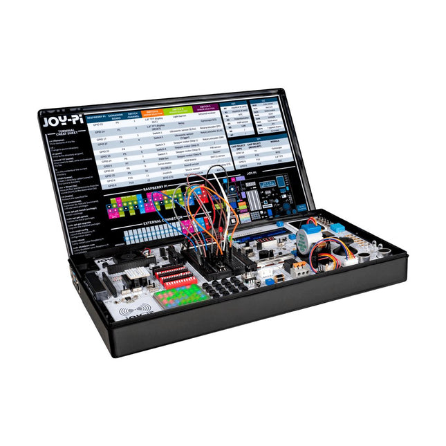
JOY-iT Joy-Pi Advanced – Development Platform for Raspberry Pi, Arduino and ESP32
The Joy-Pi Advanced is a compact and powerful device that allows you to realize your projects quickly and easily. Whether you already have a lot of experience, or next to none, the Joy-Pi Advanced lets you unleash your creativity. Thanks to its compatibility with a wide range of platforms, including Raspberry Pi, Raspberry Pi Pico, Arduino Nano, BBC micro:bit, and NodeMCU ESP32, you can easily and quickly access your preferred platform. In addition, the Joy-Pi Advanced features more than 30 stations, lessons, and modules, giving you an unlimited variety of ways to get your projects done. With the self-developed learning center, you can not only improve your skills but also create new projects. The learning center offers a wealth of information and tutorials that will guide you step by step through your projects. Joy-Pi Advanced is characterized in particular by its intelligent switch units, which allow an extended use of the available pins. A total of three switch units are integrated, each equipped with 12 individual switches that provide precise control of the connected sensors and modules. This system solves the well-known problem of limited pin count that occurs with conventional microcontrollers. The switch units allow you to operate a large number of sensors and modules in parallel by switching them on and off individually. This simulates multiple pin assignment, allowing you to exploit the full power of your projects without compromising functionality. By combining innovative adapter boards and the micro:bit slot, you can achieve seamless compatibility with a wide range of microcontrollers such as Raspberry Pi Pico, NodeMCU ESP32, micro:mit and Arduino Nano. The specially developed adapter boards are designed to perfectly match the respective microcontroller. By plugging the microcontroller onto the appropriate adapter board and then plugging it into the micro:bit slot, the Joy-Pi Advanced quickly and easily becomes compatible with the different microcontrollers. This allows seamless integration of your preferred platform and the ability to combine the strengths of the different microcontrollers in your projects. This way, you can fully focus on your creative projects without worrying about the compatibility of different microcontrollers. The Joy-Pi Advanced simplifies the development process and gives you the possibility to design your projects flexibly and individually. Features Highly integrated development platform & learning center Fast, easy & wireless combination of various sensors & actuators Installation option for Raspberry Pi 4 Compatible with various microcontrollers Self-developed, didactic learning platform for Raspberry Pi & Windows Specifications Compatible to Raspberry Pi 4, Arduino Nano, NodeMCU ESP32, BBC micro:bit, Raspberry Pi Pico Installed sensors, actuators & components 39 Learning platform Over 40 entries in the know-ledge database, 10 projects, 10 learning tasks, 14 visions Displays 7-segment display, 16x2 display, 1.8“ TFT display, 0.96" OLED display, 8x8 RGB matrix Sensors DS18B20, shock sensor, hall sensor, barometer, sound sensor, gyroscope, PIR sensor, Light barrier, NTC, Light sensor, 6x touch sensor, color sensor, ultrasonic distance sensor, DHT11 temperature & humidity sensor Control Joystick, 5x switches, potentiometer, rotary encoder, 4x4 button matrix, relays, PWM fan Motors Servo interface, Stepper motor interface, Vibration motor Measuring & conversion modules Analog-Digital Converter, Level converter, voltmeter, Variable voltage supply Other components RTC real time clock, buzzer, EEPROM memory, infrared receiver, breadboard, RFID reader Adapter boards Adapter for NodeMCU ESP32, Arduino Nano & Raspberry Pi Pico, Board connectors for Raspberry Pi & External Boards Electronic components Infrared remote control, RFID chip, RFID card, 6x alligator clips, microSD card reader, servo motor, stepper motor, 32 GB microSD card Components 40x resistors, 3x green LEDs, 3x yellow LEDs, 3x red LEDs, 1x transistor, 5x buttons, 1x potentiometer, 2x capacitors Other accessories Screw assortment, screwdriver, accessory storage bag, power supply & power cable, servo mount Power supply Built-in power supply: 36 W, 12 V, 3 A Case connector: Small device plug C8 Voltage outputs 12 V, 5 V, 3.3 V, Variable voltage output (2-11 V) Data buses & signal outputs I²C, SPI, Analog to digital converter Battery (RTC) CR2032 Dimensions 327 x 200 x 52 mm Required Raspberry Pi 4 with at least 2 GB RAM Downloads Joy-Pi website Datasheet Manual
-
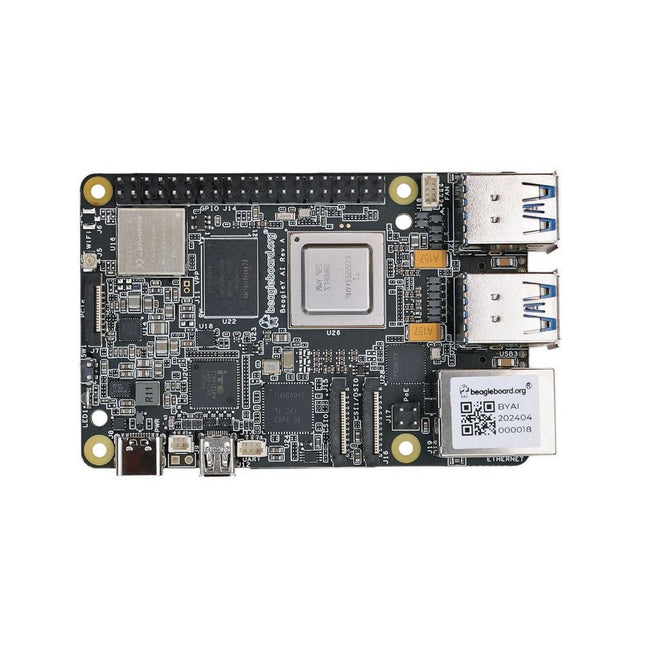
BeagleBoard BeagleY-AI SBC with GPU, DSP and AI Accelerators
BeagleY-AI is a low-cost, open-source, and powerful 64-bit quad-core single-board computer, equipped with a GPU, DSP, and vision/deep learning accelerators, designed for developers and makers. Users can take advantage of BeagleBoard.org's provided Debian Linux software images, which include a built-in development environment. This enables the seamless running of AI applications on a dedicated 4 TOPS co-processor, while simultaneously handling real-time I/O tasks with an 800 MHz microcontroller. BeagleY-AI is designed to meet the needs of both professional developers and educational environments. It is affordable, easy to use, and open-source, removing barriers to innovation. Developers can explore in-depth lessons or push practical applications to their limits without restriction. Specifications Processor TI AM67 with quad-core 64-bit Arm Cortex-A53, GPU, DSP, and vision/deep learning accelerators RAM 4 GB LPDDR4 Wi-Fi BeagleBoard BM3301 module based on TI CC3301 (802.11ax Wi-Fi) Bluetooth Bluetooth Low Energy 5.4 (BLE) USB • 4x USB-A 3.0 supporting simultaneous 5 Gbps operation• 1x USB-C 2.0 supports USB 2.0 device Ethernet Gigabit Ethernet, with PoE+ support (requires separate PoE+ HAT) Camera/Display 1x 4-lane MIPI camera/display transceivers, 1x 4-lane MIPI camera Display Output 1x HDMI display, 1x OLDI display Real-time Clock (RTC) Supports an external button battery for power failure time retention. It is only populated on EVT samples. Debug UART 1x 3-pin debug UART Power 5 V/5 A DC power via USB-C, with Power Delivery support Power Button On/Off included PCIe Interface PCI-Express Gen3 x1 interface for fast peripherals (requires separate M.2 HAT or other adapter) Expansion Connector 40-pin header Fan connector 1x 4-pin fan connector, supports PWM speed control and speed measurement Storage microSD card slot, with support for high-speed SDR104 mode Tag Connect 1x JTAG, 1x Tag Connect for PMIC NVM Programming Downloads Pinout Documentation Quick start Software
-
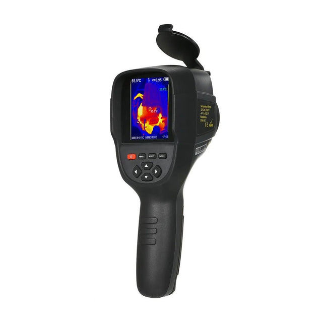
Hti Hti HT-18+ Thermal Imaging Camera (256x192)
The Hti HT-18+ is a professional thermal imaging camera designed for precise temperature measurements and real-time thermal imaging. It has an impressive infrared resolution of 256 x 192 pixels at a frame rate of 25 Hz, resulting in clear and detailed thermal images. The temperature measurement range extends from −20°C to +550°C, with a measurement accuracy of ±2°C or ±2%. The camera is equipped with a 3.2-inch color display for easy viewing of thermal images. It offers five different color palettes – rainbow, iron red, cold color, black and white and white and black – to adapt the display to different requirements. It also has a built-in memory of 4 GB for storing images and videos in JPG or MP4 format, which can be transferred to a computer via a USB connection. Specifications Infrared resolution 256 x 192 Infrared response band 8 to 14 μm Cell size 12 μm NETD ≤50 mK @ 25°C, @F/1.1 Lens focal length 3.2 mm IFOV 3.75 mrad Field angle 56° x 42° Focus mode Free focus Temperature measurement range −20°C~550°C (−4~1022°F) Measurement accuracy −15°C to 550°C (±2°C or ±2%)−20°C to −15°C (±4°C) Temperature measurement resolution 0.1°C Temperature measurement mode Center point/hot and cold spot tracking Color palette Rainbow, iron oxide red, cold color, black & white, white & black Emissivity setting Adjustable from 0.01 to 1.00 Thermal imaging frame rate ≤25 Hz Visible light resolution 640 x 480 Display size 3.2-inch (240 x 320) Image display mode Infrared/visible light/dual light fusion Device storage Built-in 4 GB eMMC (user available storage space is about 3 GB Storage Image/Video Format JPG/MP4 Image/video export method USB connection to computer export Image analysis function Support offline analysis on PC Battery Type Dedicated removable rechargeable Lithium battery Battery capacity 2200 mAh Working time 2 to 3 hours Power interface Micro USB Power configuration 5 minutes, 20 minutes, no automatic shutdown Working temperature −10°C to +50°C Relative humidity 10% to 85% RH (non-condensing) Menu languages English, German, Italian, Chinese Dimensions 90 x 105 x 223 mm Weight 389 g Included 1x Hti HT-18+ Thermal Imaging Camera 1x USB cable 1x Manual Downloads Manual
-

Sequent Microsystems Sequent Microsystems Home Automation V4 8-Layer Stackable HAT for Raspberry Pi
The Home Automation HAT uses only pluggable connectors. In addition, the latest release (V4.0 and up) has two new communication ports: 1-Wire and RS485. The card uses only 5 V power. On-board step-up power supply generates 12 V to power the 0-10 V analog outputs. A general purpose push-button, wired directly to a Raspberry Pi GPIO pin, can be used to shut down Raspberry Pi without a keyboard, or to force any output to a desired state. Ideal solution for your Raspberry Pi Home Automation projects. Read temperatures in up to 8 zones with analog inputs. Control your heating and cooling system with the 8 onboard relays. Use the 8 optically isolated digital inputs for your security system. Activate the hardware watchdog to monitor and power cycle the Raspberry Pi in case of software lockup. Control four-light systems with the four PWM open-drain outputs (you supply external power up to 24 V). Control four light dimmers using 0-10 V outputs. Compatibility The card is compatible with all Raspberry Pi versions from Zero to 4. It shares the I²C bus using only two of the Raspberry Pi’s GPIO pins to manage all eight cards. This feature leaves the remaining 24 GPIOs available for the user. Power Requirements The Home Automation card needs 5 V to operate and can be powered from Raspberry Pi or from its own pluggable connector. The onboard relay coils are also powered from the 5 V. An on-board 5V to 12V step-up power supply generates the voltage to drive the 0-10 V analog outputs. A local 3.3 V regulator powers the rest of the circuitry. The card needs 50 mA to operate with all relays off. Each relay needs up to 80 mA to turn on. Relays The 8 on-board relays have contacts brought out to heavy duty pluggable connectors, which make the card easy to use when multiple cards are stacked up. Relays are grouped in two sections of four relays each, with one common terminal and one N-O contact for each relay. Relays are rated 10 A/24 VDC and 250 VAC, but due to the board geometry limitation, the relays can switch only 3 A and 24 V, AC or DC. Status LEDs show when RELAYS are ON or OFF. Stacking Multiple Cards Up to eight Home Automation cards can be stacked on your Raspberry Pi. Each card is identified by jumpers you install to indicate the level in the stack. Cards can be installed in any order. The three position jumper on the upper right corner of the card selects the stack level. Features Eight relays with status LEDs and and N.O contacts Eight layer stackable Eight 12-bit A/D inputs, 250 Hz sample rate Four 13-bit DAC outputs (0-10 V dimmers) Four PWM 24 V/4 A open-drain outputs Eight optically isolated digital inputs Contact closure/Event counters up to 500 Hz Four Quadrature Encoder inputs 26 GPIOs from Raspberry Pi available 1-WIRE and RS485 communication ports Pluggable Connectors 26-16 AWG for all ports On-board hardware watchdog On-board resettable fuse Reverse power supply protection Brass stand-offs, screws and nuts included Hardware self-test with loop-back cable Open source hardware, schematics available 32-bit Processor running at 64 MHz Uses only I²C port (address 0x28..0x2f ), all GPIO pins available Specifications Power supply: Pluggable Connector, 5 V/3 A Power consumption: 50 mA (all relays off), 700 mA (all relays on) On board resettable fuse: 3 A Open Drain outputs: maximum 3 A, 24 V Relays 1,2,3,4,5,8: N-O contacts, 6 A/24 VAC or DC Relays 6,7: 3 A/24 VAC or DC Analog Inputs: Maximum input voltage: 3 V Input Impedance: 50 KΩ Resolution: 12 bits Sample rate: 250 samples/sec. DAC Outputs: Resistive load: Minimum 1 KΩ Accuracy: ±1% Opto-isolated Digital Inputs: Input Forward Current: Typical 5 mA, maximum 50 mA Input Series Resistor: 1K Input Reverse Voltage: 5 V Input Forward Voltage: 25 V @ 10 mA Isolation Resistance: Minimum 1012 Ω Included Home Automation stackable Card for Raspberry Pi with self-test Card Mounting hardware 4x M2.5x18 mm male-female brass standoffs 4x M2.5x5 mm brass screws 4x M2.5 brass nuts 2x Stack level Jumpers All required Connector Plugs Laminated Plastic Card showing IO Pinout Downloads User's Guide Open Source Hardware Schematic 2D CAD Drawing Command Line Python Libraries Node-RED Nodes Domoticz Plugin OpenPLC
-
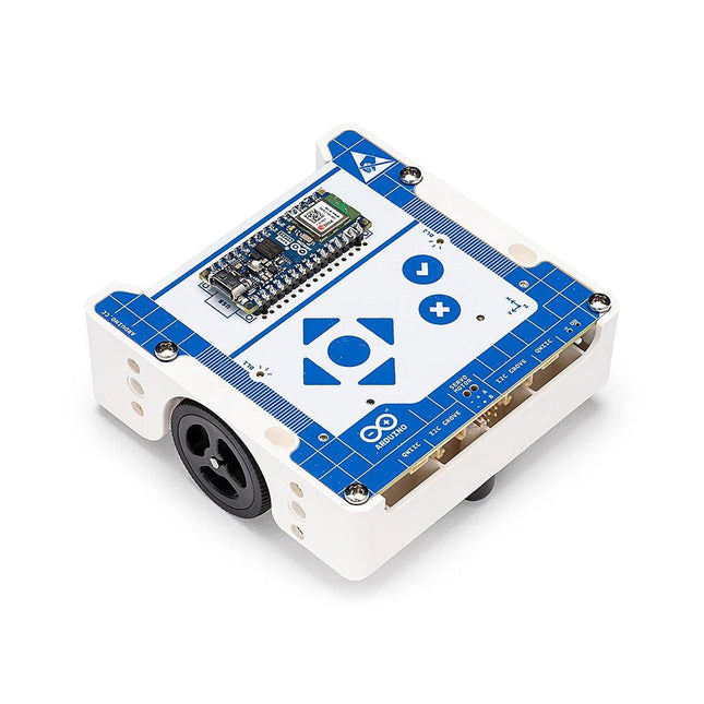
Arduino Arduino Alvik
Arduino Alvik is a powerful and versatile robot specifically designed for programming and robotics education. Powered by the Arduino Nano ESP32, Arduino Alvik offers diverse learning paths through different programming languages, including MicroPython, Arduino C, and block-based coding, enabling different possibilities to explore robotics, IoT and AI. Arduino Alvik simplifies coding and complex robot projects, enabling users of all levels to immerse themselves in the exciting world of programming and robotics. It’s also a cross-discipline tool that bridges the gap between education and the future of robotics with CSTA and NGSS-Aligned free courses. This innovative and versatile robot makes learning and creating more accessible and fun than ever before. Features Powered by the versatile Nano ESP32, Alvik streamlines the learning curve in robotics with its comprehensive programming suite that includes MicroPython and Arduino language. Designed to accommodate users of all skill levels, Alvik soon plans to introduce block-based coding, further enhancing accessibility for younger students and providing an engaging entry point into robotics design. Alvik’s Time of Flight, RGB color and line-following array sensors, along with its 6-axis gyroscope and accelerometer, allow users to tackle a range of innovative, real-world projects. From an obstacle avoidance robot to a smart warehouse automation robot car, the possibilities are endless! Alvik comes equipped with LEGO Technic connectors, allowing users to personalize the robot and expand its capabilities. Additionally, it features M3 screw connectors for custom 3D or laser-cutter designs. The Servo, I²C Grove, and I²C Qwiic connectors allow users to expand Alvik’s potential and take robotics projects to a whole new level. Add motors for controlling movement and robotic arms, or integrate extra sensors for data collection and analysis. Specifiations Alvik main controller Arduino Nano ESP32: 8 MB of RAM u-blox NORA-W106 (ESP32-S3) Processor up to 240 MHz ROM 384 kB + SRAM 512 kB 16 MB External FLASH Alvik on-board Core STM32 Arm Cortex-M4 32 Bit Power supply Nano ESP32 USB-C rechargeable and replaceable 18650 Li-Ion battery (included) Programming language MicroPython, Arduino & block-based programming Connectivity Wi-Fi, Bluetooth LE Inputs Time of Flight Distance Sensor (up to 350 cm)RGB Color Sensor6-axis Gyroscope-Accelerometer3x Line follower Array7x Touchable Buttons Outputs 2x RGB LEDs6 V Motors (No load speed 96 rpm, No load current 70 mA) Extensions 4x LEGO Technic connectors8x M3 screw connectorsServo motorI²C GroveI²C Qwiic Downloads Datasheet Documentation
-
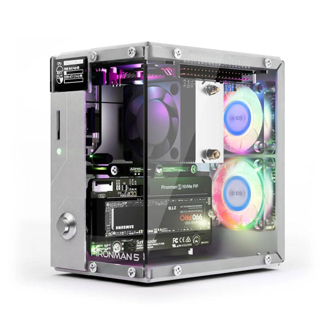
SunFounder Pironman 5 NVMe M.2 SSD PCIe Mini PC Case for Raspberry Pi 5
Enhance your Raspberry Pi 5 with the Pironman 5, built with sturdy aluminum, superior cooling, NVMe M.2 SSD support, OLED display, RGB lighting, standard HDMI ports x2, and a secure power switch. It is perfect for NAS, Home Assistant, Media and Game Centers. The Pironman 5 is not just a case; it’s an upgrade that transforms your Raspberry Pi 5 into a powerful, efficient, and stylish device. The Pironman 5 includes the Pi 5 NVMe PIP (PCIe Peripheral Board), a PCIe adapter board specifically designed for NVMe solid-state drives. This board supports four sizes of NVMe SSDs: 2230, 2242, 2260, and 2280, all of which can be installed in an M.2 M key slot. The connection is certified for Gen 2.0 speeds (5 GT/sec), but can be forced to Gen 3.0 (10 GT/sec) for faster performance. Expandable NVMe M.2 SSD Slot Boost your Raspberry Pi 5's performance with the Pironman 5's NVMe M.2 SSD slot, supporting multiple sizes (2230, 2242, 2260, 2280) for increased storage and faster system response. Advanced Cooling System Keep your Raspberry Pi 5 cool and stylish with the Pironman 5's tower cooler and dual RGB fans, featuring dust filters for durable, low-maintenance operation. OLED Display for Instant Insights The Pironman 5 includes a 0.96" OLED display, providing immediate updates on CPU and RAM usage, temperature, IP address, and more. Enhanced Functionality and Safety The Pironman 5 secures your Raspberry Pi 5 with features like safe shutdown, customizable RGB LEDs, HDMI ports, an IR receiver, and an external GPIO extender, enhancing functionality and connectivity. Features Raspberry Pi 5 mini PC 0.96" OLED Display showing Raspberry Pi’s CPU usage, temperature, disk usage, IP address, RAM usage etc. Tower cooler can cool a 100% CPU load Pi to 39°C at 25°C room temperature 2 RGB Fans, with GPIO control 1 PWM Fan on the Tower Cooler is controlled by the Raspberry Pi system. Supports four (PCIe Gen 2.0 / PCIe Gen 3.0) NVMe M.2 SSD sizes: 2230, 2242, 2260, and 2280. 4 WS2812 Addressable RGB LED light up the whole case with cool light effect IR Receiver for multi-media center like Kodi or Volumio Retro metal power button for safe shut down External GPIO extender with pin name label, for easy access Equipped with a spring-loaded socket for easy card removal Aluminum main body with clear Acrylic side panel Features two standard HDMI ports Downloads Documentation
-

Arduino Arduino Pro Portenta X8
Portenta X8 is a powerful, industrial-grade SOM with Linux OS preloaded onboard, capable of running device-independent software thanks to its modular container architecture. Take advantage of onboard Wi-Fi/Bluetooth Low Energy connectivity to securely perform OS/application OTA updates. It’s basically two industrial products in one, with the power of no less than 9 cores. Leverage the Arduino environment to carry out real-time tasks while Linux takes care of high-performance processing. Portenta X8 features an NXP i.MX 8M Mini Cortex-A53 quad-core, up to 1.8 GHz per core + 1x Cortex-M4 up to 400 MHz, plus the STMicroelectronics STM32H747 dual-core Cortex-M7 up to 480 Mhz +M4 32-bit ARM MCU up to 240 Mhz. Features Two industrial products in one, combining Arduino’s availability of libraries/skills with container-based Linux distribution Outstanding computational density – a total of 9 cores within a compact form factor Multi-processor architecture allowing power-optimized processing Leverage popular programming languages like Python, Java and Ruby among others Real-time I/O and fieldbus/control on a dedicated core Deploy powerful AI algorithms and machine learning on the edge Secure OS/applications updates over-the-air Industrial-grade security at the hardware level, thanks to its crypto chip on dedicated bus Leverage the Arduino ecosystem to expand Portenta capabilities Implement multi-protocol routing with a single module Compatible with other Arduino Portenta products Industrial-Grade Security Portenta X8 has been designed with industrial-grade security in mind. PSA Certified and includes the NXP SE050C2 hardware security element to provide key generation, accelerated crypto operations and secure storage. Awarded Arm SystemReady certification and integrated Parsec services, making it one of the market’s first Cassini Products available to developers. Portenta X8 includes the customizable open-source Linux microPlatform OS, built using best industry practices for end-to-end security, incremental OTA updates and fleet management. Utilizing the cloud-based DevOps platform from Foundries.io to reinvent the way embedded Linux solutions are built, tested, deployed and maintained, the Portenta X8 benefits from Foundries.io continuous update service for cybersecurity. This service guarantees an updated image that contains all vulnerability patches; whilst the approach to containers decouples the operating system from the application, to seamlessly keep the whole system updated. Applications Portenta X8 enables IT professionals, system integrators and consulting firms to build and boost a wide variety of solutions for industrial contexts, and also lends itself to building automation and smart agriculture applications. Connected edge computer for manufacturing Autonomous Guided Vehicles (AGV) Interactive full-HD secure kiosks and digital signage Office & home control systems Navigation and control for smart agriculture Behavioral analytics for offices and factories Downloads Datasheet Schematics
-
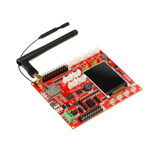
Elecrow RA-08H LoRaWAN Development Board with integrated RP2040 and 1.8" LCD (EU868)
Lora technology and Lora devices have been widely used in the field of the Internet of Things (IoT), and more and more people are joining and learning Lora development, making it an indispensable part of the IoT world. To help beginners learn and develop Lora technology better, a Lora development board has been designed specifically for beginners, which uses RP2040 as the main control and is equipped with the RA-08H module that supports Lora and LoRaWAN protocols to help users realize development. RP2040 is a dual-core, high-performance, and low-power ARM Cortex-M0+ architecture chip, suitable for IoT, robots, control, embedded systems, and other application fields. RA-08H is made from the Semtech-authorized ASR6601 RF chip, which supports the 868 MHz frequency band, has a 32 MHz MCU built-in, which has more powerful functions than ordinary RF modules, and also supports AT command control. This board retains various functional interfaces for development, such as the Crowtail interface, the common PIN to PIN header that leads out GPIO ports, and provides 3.3 V and 5 V outputs, suitable for the development and use of commonly used sensors and electronic modules on the market. In addition, the board also reserves RS485 interface, SPI, I²C, and UART interfaces, which can be compatible with more sensors/modules. In addition to the basic development interfaces, the board also integrates some commonly used functions, such as a buzzer, a custom button, red-yellow-green three-color indicator lights, and a 1.8-inch SPI interface LCD screen with a resolution of 128x160. Features Uses RP2040 as the main controller, with two 32-bit ARM Cortex M0+ processor cores (dual-core), and provides more powerful performance Integrates the RA-08H module with 32 MHz MCU, supports the 868 MHz frequency band and AT command control Abundant external interface resources, compatible with Crowtail series modules and other common interface modules on the market Integrates commonly used functions like buzzer, LED light, LCD display and custom button, making it more concise and convenient when creating projects Onboard 1.8-inch 128x160 SPI-TFT-LCD, ST7735S driver chip Compatible with Arduino/Micropython, easy to carry out different projects Specifications Main Chip Raspberry Pi RP2040, built-in 264 KB SRAM, onboard 4 MB Flash Processor Dual Core Arm Cortex-M0+ @ 133 MHz RA-08H Frequency band 803-930 MHz RA-08H Interface External antenna, SMA interface or IPEX first-generation interface LCD Display Onboard 1.8-inch 128x160SPI-TFT-LCD LCD Resolution 128x160 LCD Driver ST7735S (4-wire SPI) Development environment Arduino/MicroPython Interfaces 1x passive buzzer 4x user-defined buttons 6x programmable LEDs 1x RS485 communication interface 8x 5 V Crowtail interfaces (2x analog interfaces, 2x digital interfaces, 2x UART, 2x I²C) 12x 5 V universal pin header IO 14x 3.3 V universal pin header IO 1x 3.3 V/5 V switchable SPI 1x 3.3 V/5 V switchable UART 3x 3.3 V/5 V switchable I²C Working input voltage USB 5 V/1 A Operating temperature -10°C ~ 65°C Dimensions 102 x 76.5 mm (L x W) Included 1x Lora RA-08H Development Board 1x Lora Spring Antenna (868 MHz) 1x Lora Rubber Antenna (868 Mhz) Downloads Wiki
-
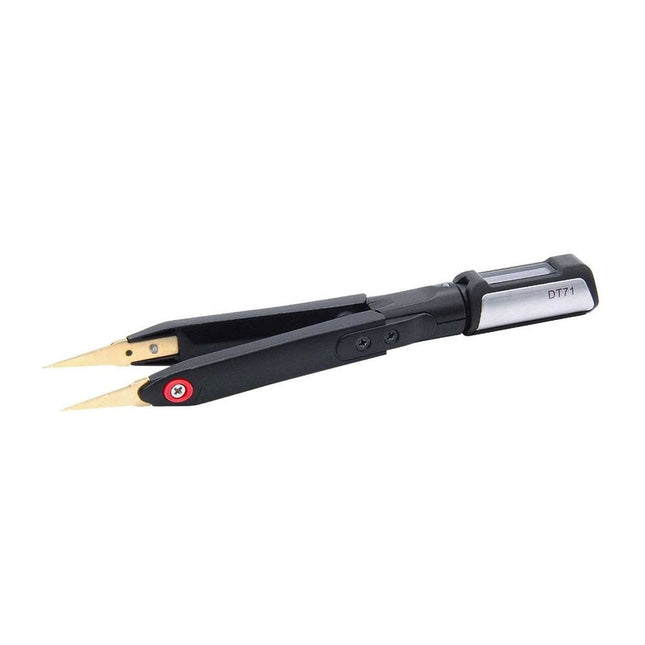
Miniware Miniware DT71 Mini Digital Tweezers
LCR/ESR Meter, Multimeter, SMD Tester with built-in Micro Signal Generator The Miniware DT71 digital tweezers are a truly 'smart' buy for pro engineers and makers alike. The compact DT71 has a unique trinary structure which can be separated into the controller, testing arms, and tweezer tips. You can use the DT71 to take measurements and to automatically identify SMD components such as resistors, capacitors, and diodes. Highlights DT71 Mini Digital Tweezers is a tool for multi-function measurements with full differential input measurement. DT71 has a unique trinary structure, which can be separated into the controller, testing arms, and tweezer tips, flexible to be replaced and combined. It is compact and pocket-size for easy carrying. You can use it in laboratories, workbenches, warehouses, and in the field. It also has dual built-in rechargeable lithium batteries that can last 10 hours at a stretch with a single full charge that takes about 2 hours to charge. DT71 Mini Digital Tweezers have an OLED screen on the 360° rotatable controller, providing visibility at all angles. Smart gesture recognition will automatically identify left/right-hand operation and adjust screen display. It has various measurement types to fulfill all your needs. The test arms of DT71 Mini Digital Tweezers use magnetic elasticity to provide an easy clipping, ergonomic, and long-lasting structure. DT71 Mini Digital Tweezers features a pair of beautiful intensified gold-plated interchangeable tweezer tips, which enables higher measuring accuracy. DT71 Mini Digital Tweezers have manual and automatic Identification modes. In auto mode, DT71 can automatically identify SMDs including resistor, capacitor, inductor, and diode, showing both main and secondary parameters, very useful in fast distinguishing different components. Meanwhile, a built-in miniature waveform signal generator can output a variety of waveform signals. DT71 provides a perfect solution for debugging and maintenance of complex electronic systems and the classification and detection of discrete chip components. Different from other LCR testers, DT71 Mini Digital Tweezers have no physical buttons, instead, it has a hidden touch button on top of the controller, which makes it easy to operate with only a light touch. DT71 Mini Digital Tweezers has intelligent functions such as Automatic identification, Automatic shutdown, and also the firmware can be upgraded. Features Innovative trinary structure: separated into the controller, testing arms, and tweezer tips, which are flexible to be replaced and combined. 360° rotatable controller with OLED screen, with good viewing angles. Smart gesture recognition with automatic identification of left/right-hand operation and adjusting the screen orientation accordingly. Hidden touch button on top of the controller, which makes it easy to operate with only a light touch. Test arms use magnetic elasticity to provide an easy clipping, ergonomic, and long-lasting structure. Built-in dual lithium batteries in test arms, balancing both arms and providing a longer standby time. Several kinds of gold-plated interchangeable tweezer tips, enabling higher measurement accuracy in various usages. Automatically identify SMDs including resistor, capacitor, inductor, and diode, showing both main and secondary parameters. A built-in signal generator can output a variety of waveform signals. Specifications Product Specifications Operation time 10 hrs (in continuous operation) Charging time 2 hrs Display 96 x 16 OLED Size Controller 47 mm Test Arms 106 mm Weight 22 g Operation Hidden touch button Measurement Specifications Range Resolution Accuracy Resistance 0.1 Ω~1 KΩ 0.1 Ω 0.5%+2 1 KΩ~2000 KΩ 1 KΩ 0.5%+2 Capacitance 0.1 pF~1000 pF 0.1 pF 2%+3 0.001uF~400 uF 0.001 uF 2%+3 Inductance 1 uH~1000 uH 1 uH 5%+3 1 mH~50 mH 1 mH 5%+3 Voltage 1 mV~100 mV 1 mV 2%+5 0.1 V~40 V 0.1 V 1%+3 Frequency 10 Hz~1 KHz 10 Hz 0.1%+3 1 KHz~20000 KHz 1 KHz 0.1%+3 Diode Silicon diodes, Schottky diodes, LEDs (+0.1~3V) 0.1 V 1% Max input voltage -5 V~+50 V Source Impedance 1 MΩ Functions Automatic Identification Yes Designated Measurements Yes Continuity and Diode testing Yes Signal Generator SINE 10 KHz, 5 KHz, 2 KHz, 1 Khz, 500 Hz, 200 Hz NOISE 100 KHz USER 10 KHz, 5 KHz, 2 KHz, 1 Khz, 500 Hz, 200 Hz PULSE 100 KHz, 0 KHz, 20 Khz, 10 KHz, 5 KHz, 2 KHz, 1 Khz, 500 Hz, 200 Hz Included 1x DT71 Digital Tweezers 1x Test Arms 2x Tweezer Tips 1x Data Cable 1x Carrying Case 1x Safety Instructions Downloads Manual Firmware v1.15 Calibration v2.0


