The ATmega328 Uno Development Board (Arduino Uno compatible) is a microcontroller board based on the ATmega328.
It has 14 digital input/output pins (of which 6 can be used as PWM outputs), 6 analogue inputs, a 16 MHz ceramic resonator, a USB connection, a power jack, an ICSP header and a reset button.
It contains everything needed to support the microcontroller; connect it to a computer with a USB cable or power it with a AC-to-DC adapter or battery to get started.
Specifications
Microcontroller
ATmega328
Operating voltage
5 V DC
Input voltage (recommended)
7-12 V DC
Input voltage (limits)
6-20 V DC
Digital I/O pins
14 (of which 6 provide PWM output)
Analogue input pins
6
SRAM
2 kB (ATmega328)
EEPROM
1 kB (ATmega328)
Flash memory
32 kB (ATmega328) of which 0.5 kB used by bootloader
Clock speed
16 MHz
Downloads
Manual
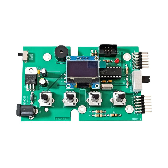
The Elektor Super Servo Tester can control servos and measure servo signals. It can test up to four servo channels at the same time.
The Super Servo Tester comes as a kit. All the parts required to assemble the Super Servo Tester are included in the kit. Assembling the kit requires basic soldering skills. The microcontroller is already programmed.
The Super Servo Tester features two operating modes: Control/Manual and Measure/Inputs.
In Control/Manual mode the Super Servo Tester generates control signals on its outputs for up to four servos or for the flight controller or ESC. The signals are controlled by the four potentiometers.
In Measure/Inputs the Super Servo Tester measures the servo signals connected to its inputs. These signals may come from for instance an ESC, a flight controller, or the receiver or another device. The signals are also routed to the outputs to control the servos or the flight controller or ESC. The results are shown on the display.
Specifications
Operating modes
Control/Manual & Measure/Inputs
Channels
3
Servo signal inputs
4
Servo signal outputs
4
Alarm
Buzzer & LED
Display
0.96' OLED (128 x 32 pixels)
Input voltage on K5
7-12 VDC
Input voltage on K1
5-7.5 VDC
Input current
30 mA (9 VDC on K5, nothing connected to K1 and K2)
Dimensions
113 x 66 x 25 mm
Weight
60 g
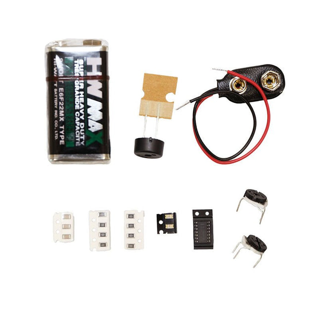
Included
Resistors (0.25 W)
R1, R3
1 kΩ, 5%
R2, R4, R5, R6, R7, R9, R10
10 kΩ, 5%
R8
22 Ω, 5%
P1, P2, P3, P4
10 kΩ, lin/B, vertical potentiometer
Capacitors
C1
100 µF 16 V
C2
10 µF 25 V
C3, C4, C7
100 nF
C5, C6
22 pF
Semiconductors
D1
1N5817
D2
LM385Z-2.5
D3
BZX79-C5V1
IC1
7805
IC2
ATmega328P-PU, programmed
LED1
LED, 3 mm, red
T1
2N7000
Miscellaneous
BUZ1
Piezo buzzer with oscillator
K1, K2
2-row, 12-way pinheader, 90°
K5
Barrel jack
K4
1-row, 4-way pin socket
K3
2-row, 6-way boxed pinheader
S1
Slide switch DPDT
S2
Slide switch SPDT
X1
Crystal, 16 MHz
28-way DIP socket for IC2
Elektor PCB
OLED display, 0.96', 128 x 32 pixels, 4-pin I²C interface
Links
Elektor Magazine
Elektor Labs
The Punk Console circuit is an advanced tutorial to get you familiar with the V-One Drill attachment. Learn how to create a double sided board and turn the knobs to create music!
The kit contains:
2x Green LEDs
8x 1k Resistors
3x 0.01uF Capacitor
2x 500K Trimpots
1x 556 Timer
1x Piezo Buzzer
1x 9 V Battery
1x 9 V Battery Connector
Rivets and a V-One Drill are required.
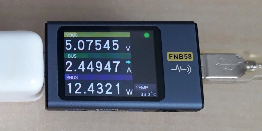
The FNIRSI FNB58 USB tester (with Bluetooth) is a comprehensive and very accurate USB voltage and current meter. It features a 2.0-inch full-color HD TFT display, built-in USB-A, micro USB and USB-C interface. With this device you can measure the power supply or power consumption of products or the charging power of cell phones and power supplies. You can also determine the fast charging protocol of chargers.
Features
USB-A and USB-C interface
2.0" HD display
Data at a glance
Wide compatibility
Ultra-precise data detection
Play with fast charging technology
Automatic protocol detection (PD2.0, 3.0, 3.1, PPS, QC2.0, 3.0, FCP, SCP, AFC, PE, DASH VOOC, SuperVOOC and more)
Simple user interface, easy to operate
4 function curve displays (real-time voltage and current curve, offline curve recording, D+/D- voltage curve, high-speed power supply ripple measurement)
Cable detection
10 groups of energy recording battery capacity calculation
PC connectivity for data logging and firmware updates
Bluetooth app for Android devices
Specifications
Voltage range
4-28 V
Current range
0-7 A
Power range
0-120 W
Load equivalent internal resistance
0-9999.9 Ω
D+/D- voltage
0-3.3 V
Capacity
0-9999.99 Ah
Power consumption
0-9999.99 Wh
Cable resistance
0-9999.9 Ω
Interfaces
micro USB, USB-A, USB-C
Dimensions
42 x 13 x 82 mm
Downloads
Manual
Firmware V0.68
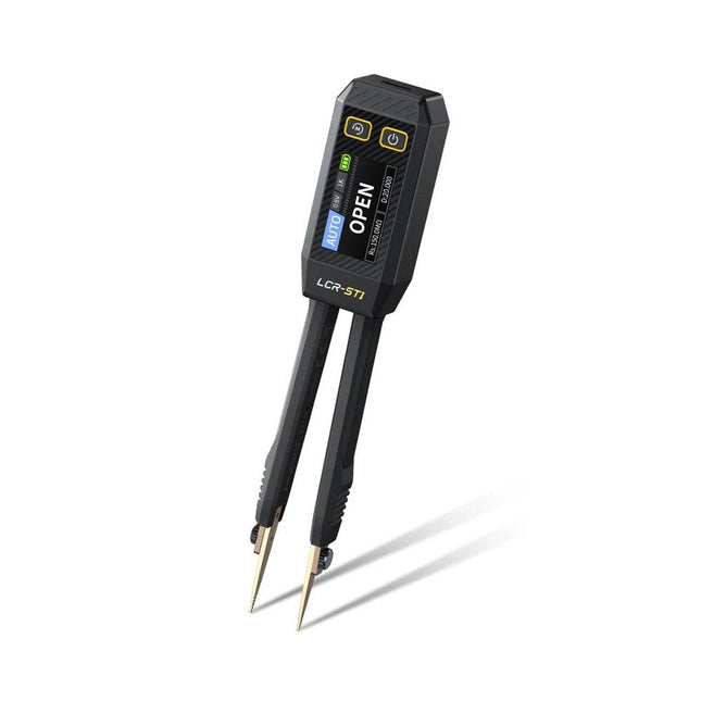
The FNIRSI LCR-ST1 is a compact, multifunctional, and smart LCR tester that supports automatic measurements of resistance, capacitance, inductance, diode testing, and continuity.
Its 1.14-inch color display combined with a convenient magnetic adsorption function enhances ease of use, while the built-in 250 mAh lithium battery ensures long-lasting performance. The device supports three frequency ranges (100 Hz, 1 kHz and 10 kHz) and offers 0.3 V and 0.6 V RMS test levels for versatile testing applications.
The unique tweezer-shaped design of the LCR-ST1 is ideal for delicate tasks in confined spaces and enables fast and accurate testing of electronic components. Its light weight and portable design make it an invaluable tool for both field and laboratory use.
Whether you are an experienced engineer or just starting out in electronics, the LCR-ST1 delivers reliable and accurate measurement results, allowing you to complete your tasks with greater efficiency and precision.
Features
Offers 3 test frequencies (100 Hz, 1 kHz, 10 kHz) and 2 test voltage levels.
Features automatic component identification for faster and more reliable measurements.
High-resolution 1.14-inch color display for clear readouts.
Supports automatic data recording and storage.
The tweezer tips are made from gold-plated brass for enhanced durability and conductivity.
Specifications
Resistance Range
10 mΩ – 10 MΩ
Capacitance Range
1 pF – 22 mF
Inductance Range
1 μh – 10 H
Diode
On voltage 0.7 V
Frequency Test
100 Hz, 1k Hz, 10 KHz
Level Test
0.3 V, 0.6 V RMS
Parameter Display
ESR, D value, Q value, Z value, X value
Display
1.14" HD color screen
Charging Interface
USB-C, 5 V/1 A
Power Supply
Built-in 250 mAh lithium battery
Auto Recognition Measurement
Yes
Replaceable Tweezer Head
Yes
Auto Shutdown
Yes
Data Hold
Yes
History Record
Connect to PC to view and export
Dimensions
28 x 19 x 150 mm
Weight
41 g
Included
1x LCR-ST1 SMD Tweezers
2x Hook Tips
1x Magnetic Patch
1x USB cable
1x Tool bag
1x Manual
Downloads
Manual
Firmware V1.6
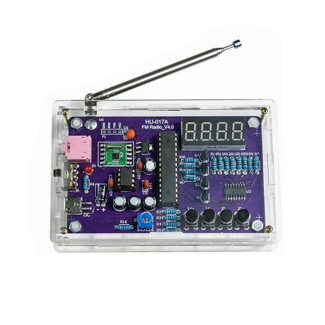
This DIY kit (HU-017A) is a wireless FM radio receiver with a 4-digit 7-segment display. It operates within the global FM receiving frequency band of 87.0-108.0 MHz, making it suitable for use in any country or region. The kit offers two power supply modes, allowing you to use it both at home and outdoors. This DIY electronic product will help you understand circuits and improve your soldering skills.
Features
87.0-108.0 MHz FM Radio: Built-in RDA5807 FM data processor with a standard FM receiving frequency band. The FM frequency can be adjusted using the F+ and F- buttons.
Adjustable Volume: Two volume adjustment methods – button and potentiometer. There are 15 volume levels.
Active & Passive Audio Output: The kit has a built-in 0.5 W power amplifier to drive 8 Ω speakers directly. It also outputs audio signals to headsets or loudspeakers with AUX interfaces, allowing personal listening and sharing of FM audio.
Configured with a 25 cm dedicated FM antenna and a (red) 4-digit 7-segment display for real-time display of FM radio frequency. The transparent acrylic shell protects the internal circuit board. It supports dual power supply methods – 5 V USB and 2x 1.5 V (AA) batteries.
DIY Hand Soldering: The kit comes with various components that need to be installed manually. It helps exercise and improve soldering skills, making it suitable for electronics hobbyists, beginners, and educational purposes.
Specifications
Operating voltage
DC 3 V/5 V
Output impedance
8 Ω
Output power
0.5 W
Output channel
Mono
Receiver frequency
87.0 MHz~108.0 MHz
Frequency accuracy
0.1 MHz
Operating temperature
−40°C to +85°C
Operating humidity
5% to 95% RH
Dimensions
107 x 70 x 23 mm
IMPORTANT: Remove the batteries when powering the radio over to USB.
Included
1x PCB
1x RDA5807M FM Receiver
1x STC15W404AS MCU
1x IC Socket
1x 74HC595D Register
1x TDA2822M Amplifier
1x IC Socket
1x AMS1117-3.3 V Voltage Converter
18x Metal Film Resistor
1x Potentiometer
4x Ceramic Capacitor
5x Electrolytic Capacitor
4x S8550 Transistor
1x Red LED
1x 4-digit 7-segment Display
1x Toggle Switch
1x SMD Micro USB Socket
1x Radio Antenna
1x AUX Audio Socket
4x Black Button
4x Button Cap
1x 0.5 W/8 Ω Speaker
1x Red/Black Wire
2x Double-sided adhesive
1x AA Battery Box
1x USB cable
6x Acrylic Board
4x Nylon Column Screw
4x M3 Screw
4x M3 Nut
4x M2x22 mm Screw
1x M2x6 mm Screw
5x M2 Nut
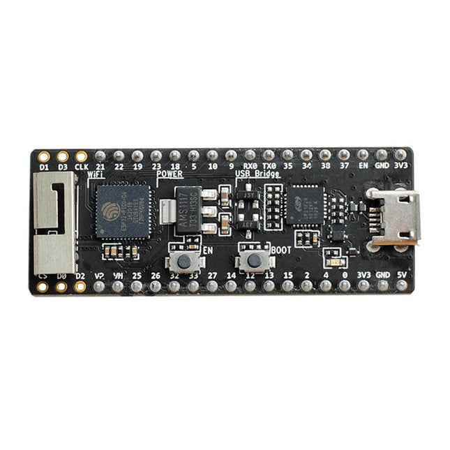
The ESP32-PICO-Kit fits into a mini breadboard. It is fully functional with the minimum number of discrete components, while it has all the ESP32 pins exposed.
Features
Complete up-to-date documentation is available.
All instructions and commands presented work as described.
Plentiful additional information and hardware documentation are available too.
Applications for the ESP32-PICO-KIT can be developed on Windows, Linux or Mac.
Two cores and a radio
Like the ESP8266 the ESP32 has Wi-Fi but adds Bluetooth. It also has two 32-bit cores inside, making it extremely powerful, and providing all the ports and interfaces that the ESP8266 is lacking.Oversimplifying things, one might say that the ESP8266 is a Wi-Fi controller that provides some I/O, whereas the ESP32 is a full-fledged controller that also has Wi-Fi.
ESP32 peripherals
The ESP32 exposes an ADC & DAC, touch sensor circuitry, an SD/SDIO/MMC host controller, an SDIO/SPI slave controller, an EMAC, PWM to control LEDs and motors, UART, SPI, I²C, I²S, infrared remote controller, and, of course, GPIO.
ESP32-PICO-KIT Development board
The ESP32-PICO-D4 is a System-on-Chip (SoC) integrating an ESP32 chip together with a 4 MB SPI flash memory in a tiny 7 x 7 mm package.
The ESP32-PICO-KIT is a breakout board for this SoC with an onboard USB-to-serial converter for easy programming and debugging.
Besides the board, you'll need a programming toolchain. Complete, up-to-date documentation from Espressif is available on the Read the Docs website.
All instructions and commands presented work as described.Plentiful additional information and hardware documentation are available too.
Applications for the ESP32-PICO-KIT can be developed on Windows, Linux or Mac.
,
by Jean-François Simon
Fnirsi FNB58 USB Tester (Review)
The Fnirsi FNB58 is a versatile USB tester capable of performing a wide array of voltage, current, and energy measurements, as well as supporting numerous...
,
by Lobna Belarbi
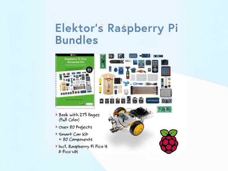
Affordable Robot Kits to Kickstart Your Robotics Journey
Robotics is an exciting and rewarding field, but getting started can be intimidating—especially when it comes to choosing the right kit. Fortunately, Elektor offers a...
,
by Lobna Belarbi
Must-Have Boards, Kits & Tools to Start Your Arduino Journey with Elektor
Whether you're a newcomer eager to explore the world of microcontrollers or an experienced maker seeking to expand your toolkit, Elektor offers a curated selection...