A Reference and User Guide for the Arduino Uno Hardware and Firmware
A manual providing up-to-date hardware information for the popular Arduino Uno, the easy to use open-source electronics platform used by hobbyists, makers, hackers, experimenters, educators and professionals.
Get all the information that you need on the hardware and firmware found on Arduino Uno boards in this handy reference and user guide.
ldeal for the workbench or desktop
Contains all of the Arduino Uno hardware information in one place
Covers Arduino / Genuino Uno revision 3 and earlier boards
Easily find hardware technical specifications with explanations
Pin reference chapter with interfacing examples
Diagrams and illustrations for easy reference to alternate pin functions and hardware connections
Learn to back up and restore firmware on the board, or load new firmware
Basic fault finding and repair procedures for Arduino Uno boards
Power supply circuits simplified and explained
Mechanical dimensions split into five easy to reference diagrams
Contains circuit diagrams, parts list and board layout reference to easily locate components
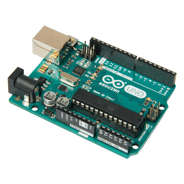
Arduino Uno is an open-source microcontroller board based on the ATmega328P. It has 14 digital input/output pins (of which 6 can be used as PWM outputs), 6 analog inputs, a 16 MHz ceramic resonator (CSTCE16M0V53-R0), a USB connection, a power jack, an ICSP header and a reset button. It contains everything needed to support the microcontroller; simply connect it to a computer with a USB cable or power it with a AC-to-DC adapter or battery to get started. You can tinker with your Uno without worring too much about doing something wrong, worst case scenario you can replace the chip for a few dollars and start over again.
'Uno' means one in Italian and was chosen to mark the release of Arduino Software (IDE) 1.0. The Uno board and version 1.0 of Arduino Software (IDE) were the reference versions of Arduino, now evolved to newer releases. The Uno board is the first in a series of USB Arduino boards, and the reference model for the Arduino platform; for an extensive list of current, past or outdated boards see the Arduino index of boards.
Specifications
Microcontroller
ATmega328P
Operating Voltage
5 V
Input Voltage (recommended)
7-12 V
Input Voltage (limit)
6-20 V
Digital I/O Pins
14 (of which 6 provide PWM output)
PWM Digital I/O Pins
6
Analog Input Pins
6
DC Current per I/O Pin
20 mA
DC Current for 3.3 V Pin
50 mA
Flash Memory
32 KB (ATmega328P) of which 0.5 KB used by bootloader
SRAM
2 KB (ATmega328P)
EEPROM
1 KB (ATmega328P)
Clock Speed
16 MHz
LED_BUILTIN
13
Dimensions
68.6 x 53.4 mm
Weight
25 g
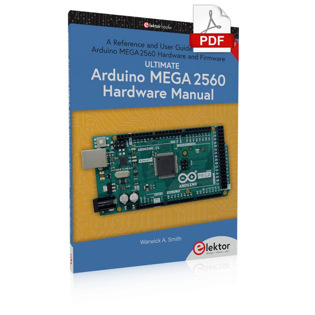
A Reference and User Guide for the Arduino Mega 2560 Hardware and Firmware
A manual providing up-to-date hardware information for the Arduino Mega 2560.
The Arduino Mega 2560 is an upgrade to the popular Arduino Uno board, providing more pins, serial ports and memory. Arduino is the easy to use open-source electronics platform used by hobbyists, makers, hackers, experimenters, educators and professionals.
Get all the information that you need on the hardware and firmware found on Arduino Mega 2560 boards in this handy reference and user guide. Ideal for the workbench or desktop. This manual covers the Arduino Mega 2560 hardware and firmware, and is a companion volume to the Ultimate Arduino Uno Hardware Manual, which covers the Arduino Uno hardware and firmware.
Contains all of the Arduino Mega 2560 hardware information in one place
Covers Arduino / Genuino Mega 2560 revision 3 and earlier boards
Easily find hardware technical specifications with explanations
Pin reference chapter with interfacing examples
Diagrams and illustrations for easy reference to pin functions and hardware connections
Learn to back up and restore firmware on the board, or load new firmware
Basic fault finding and repair procedures for Arduino Mega 2560 boards
Power supply circuits simplified and explained
Mechanical dimensions split into five easy to reference diagrams
Contains circuit diagrams, parts list and board layout to easily locate components
A chapter on shield compatibility explains how shields work across different Arduino boards
Programming and Projects for the Minima and WiFi
Based on the low-cost 8-bit ATmega328P processor, the Arduino Uno R3 board is likely to score as the most popular Arduino family member so far, and this workhorse has been with us for many years. Recently, the new Arduino Uno R4 was released, based on a 48-MHz, 32-bit Cortex-M4 processor with a huge amount of SRAM and flash memory. Additionally, a higher-precision ADC and a new DAC are added to the design. The new board also supports the CAN Bus with an interface.
Two versions of the board are available: Uno R4 Minima, and Uno R4 WiFi. This book is about using these new boards to develop many different and interesting projects with just a handful of parts and external modules, which are available as a kit from Elektor. All projects described in the book have been fully tested on the Uno R4 Minima or the Uno R4 WiFi board, as appropriate.
The project topics include the reading, control, and driving of many components and modules in the kit as well as on the relevant Uno R4 board, including
LEDs
7-segment displays (using timer interrupts)
LCDs
Sensors
RFID Reader
4×4 Keypad
Real-time clock (RTC)
Joystick
8×8 LED matrix
Motors
DAC (Digital-to-analog converter)
LED matrix
WiFi connectivity
Serial UART
CAN bus
Infrared controller and receiver
Simulators
… all in creative and educational ways with the project operation and associated software explained in great detail.
The Uno differs from all preceding boards in that it does not use the FTDI USB-to-serial driver chip. Additional features coming with the R3 version are: ATmega16U2 instead of 8U2 as a USB-to-Serial converter. 1.0 pinout: added SDA and SCL pins for TWI communication placed near to the AREF pin and two other new pins placed near to the RESET pin, the IOREF that allow the shields to adapt to the voltage provided from the board and the second one is a not connected pin, that is reserved for future purposes. stronger RESET circuit. Microcontroller ATmega328P Operating Voltage 5 V Input Voltage 7 V - 12 V Digital I/O Pins 14 PWM Pins 6 Analog Input Pins 8 DC Current per I/O Pin 20 mA DC Current for 3.3 V Pin 50 mA Flash Memory 32 KB (ATmega328P) of which 0.5 KB used by bootloader SRAM 2 KB EEPROM 1 KB Clock Speed 16 MHz LED_Builtin 13 Length 68.6 mm Width 53.4 mm Weight 25 g
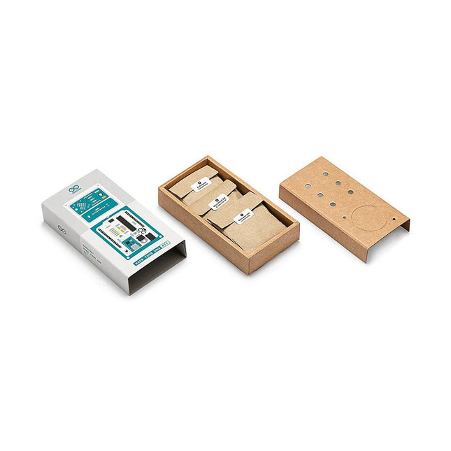
Learn the basics of electronics by assembling manually your Arduino Uno, become familiar with soldering by mounting every single component, and then unleash your creativity with the only kit that becomes a synth!
The Arduino Make-Your-Uno kit is really the best way to learn how to solder. And when you are done, the packaging allows you to build a synth and make your music.
A kit with all the components to build your very own Arduino Uno and audio synthesizer shield.
The Make-Your-Uno kit comes with a complete set of instructions in a dedicated content platform. This includes video material, a 3D interactive viewer for following detailed instructions, and how to program your board once it is finished.
This kit contains:
Arduino Make-Your-Uno
1x Make-Your-Uno PCB
1x USB C Serial adapter Board
7x Resistors 1k Ohm
2x Resistors 10k Ohm
2x Resistors 1M Ohm
1x Diode (1N4007)
1x 16 MHz Crystal
4x Yellow LEDs
1x Green LED
1x Push-Button
1x MOSFET
1x LDO (3.3 V)
1x LDO (5 V)
3x Ceramic capacitors (22pF)
3x Electrolytic capacitors (47uF)
7x Polyester capacitors (100nF)
1x Socket for ATMega 328p
2x I/O Connectors
1x Connector header 6 pins
1x Barrel jack connector
1x ATmega 328p Microcontroller
Arduino Audio Synth
1x Audio Synth PCB
1x Resistor 100k Ohm
1x Resistor 10 Ohm
1x Audio amplifier (LM386)
1x Ceramic capacitors (47nF)
1x Electrolytic capacitors (47uF)
1x Electrolytic capacitors (220uF)
1x Polyester capacitor (100nF)
4x connectors pin header
6x potentiometer 10k Ohm with plastic knobs
Spare parts
2x Electrolytic capacitors (47uF)
2x Polyester capacitor (100nF)
2x Ceramic capacitors (22pF)
1x Push-Button
1x Yellow LEDs
1x Green LED
Mechanical parts
5x Spacers 12 mm
11x Spacers 6 mm
5x screw nuts
2x screws 12 mm
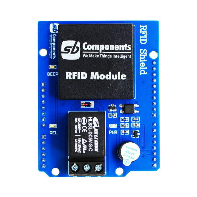
Designed with convenience and security in mind, the Ardi RFID Shield is based on the EM-18 module, operating at a frequency of 125 KHz. This shield allows you to easily integrate RFID (Radio Frequency Identification) technology into your projects, enabling seamless identification and access control systems.
Equipped with a powerful 1-channel optoisolated relay, the Ardi RFID Shield offers a reliable switching solution with a maximum DC rating of 30 V and 10 A, as well as an AC rating of 250 V and 7 A. Whether you need to control lights, motors, or other high-power devices, this shield provides the necessary functionality.
Additionally, the Ardi RFID Shield features an onboard buzzer that can be utilized for audio feedback, allowing for enhanced user interaction and system feedback. With the onboard 2-indication LEDs, you can easily monitor the status of RFID card detection, power supply, and relay activation, providing clear visual cues for your project's operation.
Compatibility is key, and the Ardi RFID Shield ensures seamless integration with the Arduino Uno platform. Paired with a read-only RFID module, this shield opens up a world of possibilities for applications such as access control systems, attendance tracking, inventory management, and more.
Features
Onboard 125 kHz EM18 RFID small, compact module
Onboard High-quality relays Relay with Screw terminal and NO/NC interfaces
Shield compatible with both 3.3 V and 5 V MCU
Onboard 3 LEDs power, relay ON/OFF State and RFID Scan status
Multi-tone Buzzer onboard for Audio alerts
Mounts directly onto ArdiPi, Ardi32 or other Arduino compatible boards
Specifications
RFID operating Frequency: 125 kHz
Reading distance: 10 cm, depending on TAG
Integrated Antenna
Relay Max Switching Voltage: 250 V AC/30 V DC
Relay Max Switching Current: 7 A/10 A
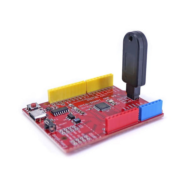
This programmer is specifically designed for burning bootloaders (without a computer) on Arduino-compatible ATmega328P/ATmega328PB development boards.
Simply plug the programmer into the ICSP interface to re-burn the bootloader. It’s also compatible with new chips, provided the IC is functional.
Note: Burning a bootloader erases all previous chip data.
Features
Working voltage: 3.1-5.3 V
Working current: 10 mA
Compatible with Arduino Uno R3 based boards (ATmega328P or ATmega328PB)
Dimensions: 39.6 x 15.5 x 7.8 mm
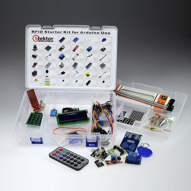
Modern electronic experimenter kits contain modules that just plug together rather than individual components so that now we can quickly get modules talking and then decide in software how the system behaves. Thanks to the wide selection of software library functions we can have a sketch up and running in no time. These kits are worthy successors to the bags of loose components that were a feature of earlier experimenter’s kits. Electronic newbies, practicing engineers and old hands alike are sure to find that these kits interesting. The range of components is sure to get you thinking what you could use them for and they are a good way to build on your existing knowledge. You’ll have no excuse not to go on to design and build your own system! The ‘RFID Starter Kit for Arduino’ comes in a handy case and contains over 30 state-of-the-art components, devices and modules. Although it contains an RFID receiver module along with two RFID tags in the form of a credit card and key fob, the case is an Aladdin’s cave with loads of other useful components. To begin you will need an Arduino Uno along with the starter kit which amongst other things contains: A humidity sensor; A multicolor LED; A large LED-Matrix with 64 LEDs; 4 x 7-segment LED displays; A handheld IR remote controller plus IR receiver chip; A complete LC-Display module with I²C bus interface. The wide range of peripherals included in the kit ensures the number of different experiments and applications you can build. Two example applications that can easily be built using this box of goodies have been described in an article published in Elektor Magazine: Universal weather station with LC-Display and Door entry system using RFID security. More similar projects have been described in the new book Home Automation Projects with Arduino. Kit Contents LCD1602 with I²C RC522 module White card Key chain Joystick module Key board RTC module Water level sensor Humidity sensor RGB module Motor driver module Motor 1 Channel module MB-102 breadboard 65 pcs jumper wire 10 PCS F-M cable Sound sensor module Remote 10 K potentiometer 1 digital tube 4 digital tube Matrix tube 9G servo Buzzer 2 pcs ball switches 3 pcs photoresistance 5 pcs switches with caps 9 V battery with DC 15 pcs LED 30 pcs resistance Flame sensor IR receive sensor 74HC595 LM35DZ Uno R3 board Documentation: Download full description of similar kit.
Programming and Projects for the Minima and WiFi
Based on the low-cost 8-bit ATmega328P processor, the Arduino Uno R3 board is likely to score as the most popular Arduino family member so far, and this workhorse has been with us for many years. Recently, the new Arduino Uno R4 was released, based on a 48-MHz, 32-bit Cortex-M4 processor with a huge amount of SRAM and flash memory. Additionally, a higher-precision ADC and a new DAC are added to the design. The new board also supports the CAN Bus with an interface.
Two versions of the board are available: Uno R4 Minima, and Uno R4 WiFi. This book is about using these new boards to develop many different and interesting projects with just a handful of parts and external modules, which are available as a kit from Elektor. All projects described in the book have been fully tested on the Uno R4 Minima or the Uno R4 WiFi board, as appropriate.
The project topics include the reading, control, and driving of many components and modules in the kit as well as on the relevant Uno R4 board, including
LEDs
7-segment displays (using timer interrupts)
LCDs
Sensors
RFID Reader
4×4 Keypad
Real-time clock (RTC)
Joystick
8×8 LED matrix
Motors
DAC (Digital-to-analog converter)
LED matrix
WiFi connectivity
Serial UART
CAN bus
Infrared controller and receiver
Simulators
… all in creative and educational ways with the project operation and associated software explained in great detail.
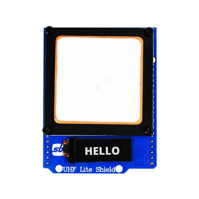
Designed with cutting-edge technology, this shield brings the power of Ultra High Frequency (UHF) RFID to your fingertips.
With the Ardi UHF Shield, you can effortlessly read up to an impressive 50 tags per second, allowing for fast and efficient data collection. The shield features an onboard UHF antenna, ensuring reliable and accurate tag detection even in challenging environments.
Equipped with a high-performance 0.91" OLED display, the Ardi UHF Shield provides clear and concise visual feedback, making it easy to monitor and interact with the RFID readings. Whether you're tracking inventory, managing access control, or implementing a smart attendance system, this shield has you covered.
With a remarkable 1-meter reading distance, the Ardi UHF Shield offers an extended range for capturing RFID data. Say goodbye to the limitations of proximity-based RFID systems and embrace the flexibility and convenience of a wider reading range.
The shield provides read-write capabilities, allowing you to not only retrieve information from RFID tags but also update or modify data as needed. This versatility opens up a world of possibilities for advanced applications and custom solutions.
Features
Onboard High-performance UHF RFID reader module
24 hours x 365 days’ work normally
0.91” OLED display for visual interaction with shield
Multi-tone Buzzer onboard for Audio alerts
Shield compatible with both 3.3 V and 5 V MCU
Mounts directly onto ArdiPi, Ardi32 or other Arduino compatible boards
Specifications
OLED resolution 128x32 pixels
I²C Interface for OLED
UHF Frequency Range (EU/UK): 865.1-867.9 MHz
UHF Module Type: Read/Write
Protocols Supported: EPCglobal UHF Class 1 Gen 2 / ISO 18000-6C
Reading Distance: 1 meters
Can identify over 50 tags simultaneously
Communication interface: TTL UART Interface for UHF
Communication baud rate: 115200 bps (default and recommend) – 38400 bps
Operation current: 180 mA @ 3.5 V (26 dBm Output, 25°C), 110 mA @ 3.5 V (18 dBm Output, 25°C)
Working humidity <95% (+25°C)
Heat-dissipating method Air cooling(no need out install cooling fin)
Tags storage capacity: 200 pcs tags @ 96 bit EPC
Output power: 18-26 dBm
Output power accuracy: +/-1 dB
Tags RSSI support