The full-colour, spiral-bound SIK guidebook (included) contains step-by-step instructions with circuit diagrams and hookup tables for building each project and circuit with the included parts. Full example code is provided, new concepts and components are explained at the point of use, and troubleshooting tips offer assistance if something goes wrong.
The kit does not require any soldering and is recommended for beginners ages 10 and up looking for an Arduino starter kit. For SIK version 4.1, Sparkfun took an entirely different approach to teaching embedded electronics. In previous versions of the SIK, each circuit focused on introducing a new piece of technology. With SIK v4.1, components are introduced in the context of the circuit you are building. Each circuit builds upon the last, leading up to a project that incorporates all of the components and concepts introduced throughout the guide. With new parts and a completely new strategy, even if you've used the SIK before, you're in for a brand-new experience!
The SIK V4.1 includes the Redboard Qwiic, which allows you to expand into the SparkFun Qwiic ecosystem after becoming proficient with the SIK circuits. The SparkFun Qwiic Connect System is an ecosystem of I²C sensors, actuators, shields and cables that make prototyping faster and less prone to error. All Qwiic-enabled boards use a common 1mm pitch, 4-pin JST connector. This reduces the amount of required PCB space, and polarized connections mean you can’t hook it up wrong. With the addition of the SparkFun RedBoard Qwiic, you will need to download a new driver install that is different from the original SparkFun RedBoard.
Included
SparkFun RedBoard Qwiic
Arduino and Breadboard Holder
SparkFun Inventor's Kit Guidebook
White Solderless Breadboard
Carrying Case
SparkFun Mini Screwdriver
16 x 2 White-on-Black LCD (with headers)
SparkFun Motor Driver (with Headers)
Pair of Rubber Wheels
Pair of Hobby Gearmotors
Small Servo
Ultrasonic Distance Sensor
TMP36 Temp Sensor
6' USB Micro-B Cable
Jumper Wires
Photocell
Tricolour LED
Red, Blue, Yellow and Green LEDs
Red, Blue, Yellow and Green Tactile Buttons
10K Trimpot
Mini Power Switch
Piezo Speaker
AA Battery Holder
330 and 10K Resistors
Binder Clip
Dual-Lock Fastener
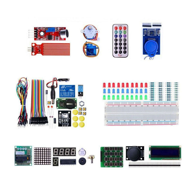
With this kit you can built all the projects described in the book 'Mastering the Arduino Uno R4'. The kit comes with several LEDs, sensors, actuators, and other components. The purpose of the kit is to make a flying start with hardware and software aspects of projects designed around the Arduino Uno microcontroller system.
Included
1x RFID reader module
1x DS1302 clock module
1x 5 V stepper motor
1x '2003' stepper motor drive board
5x Green LED
5x Yellow LED
5x Red LED
2x Rocker switch
1x Flame sensor
1x LM35 sensor module
1x Infrared receiver
3x Light-dependent resistors (LDRs)
1x IR remote controller
1x Breadboard
4x Pushbutton (with four caps)
1x Buzzer
1x Piezo sounder
1x Adjustable resistor (potentiometer)
1x 74HC595 shift register
1x 7-segment display
1x 4-digit 7-segment display
1x 8x8 Dot-matrix display
1x 1602 / I²C LCD module
1x DHT11 Temperature and humidity module
1x Relay module
1x Sound module
Set of Dupont cables
Set of Breadboard cables
1x Water sensor
1x PS2 Joystick
5x 1 k-ohm resistor
5x 10 k-ohm resistor
5x 220-ohm resistor
1x 4x4 keypad module
1x 9g Servo (25 cm)
1x RFID card
1x RGB module
1x 9 V battery DC jack
Not included
Mastering the Arduino Uno R4 (Book)
Arduino Uno R3/R4 (Board)
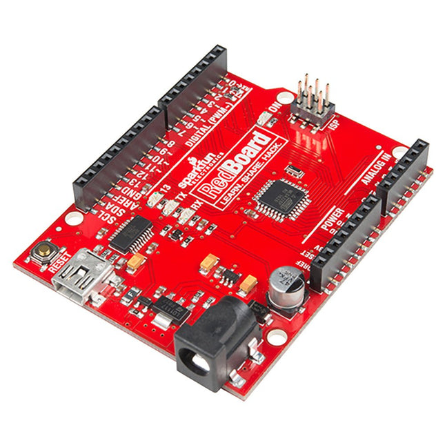
Are you tired of all the different Arduino boards, and having to choose which features you need? Wouldn't it be much simpler to have all the best features on the same board and not have to compromise? That is precisely what the people at SparkFun thought and delivered the fantastic SparkFun RedBoard Programmed with Arduino. Features ATmega328 microcontroller with Optiboot (UNO) Bootloader Input voltage: 7-15 V 0-5 V outputs with 3.3 V compatible inputs 6 Analog Inputs 14 Digital I/O Pins (6 PWM outputs) ISP Header 16 MHz Clock Spee 32 k Flash Memory R3 Shield Compatible All SMD Construction USB Programming Facilitated by the Ubiquitous FTDI FT231X Red PCB The SparkFun RedBoard combines the stability of the FTDI, the simplicity of the Uno's Optiboot bootloader, and the R3 shield compatibility of the Uno R3. RedBoard has the hardware peripherals you are used to: 6 Analog Inputs 14 Digital I/O pins (6 PWM pins) SPI UART External interrupts Downloads Drivers GitHub
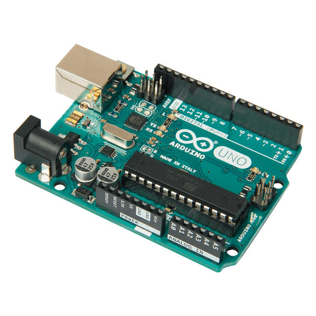
Arduino Uno is an open-source microcontroller board based on the ATmega328P. It has 14 digital input/output pins (of which 6 can be used as PWM outputs), 6 analog inputs, a 16 MHz ceramic resonator (CSTCE16M0V53-R0), a USB connection, a power jack, an ICSP header and a reset button. It contains everything needed to support the microcontroller; simply connect it to a computer with a USB cable or power it with a AC-to-DC adapter or battery to get started. You can tinker with your Uno without worring too much about doing something wrong, worst case scenario you can replace the chip for a few dollars and start over again.
'Uno' means one in Italian and was chosen to mark the release of Arduino Software (IDE) 1.0. The Uno board and version 1.0 of Arduino Software (IDE) were the reference versions of Arduino, now evolved to newer releases. The Uno board is the first in a series of USB Arduino boards, and the reference model for the Arduino platform; for an extensive list of current, past or outdated boards see the Arduino index of boards.
Specifications
Microcontroller
ATmega328P
Operating Voltage
5 V
Input Voltage (recommended)
7-12 V
Input Voltage (limit)
6-20 V
Digital I/O Pins
14 (of which 6 provide PWM output)
PWM Digital I/O Pins
6
Analog Input Pins
6
DC Current per I/O Pin
20 mA
DC Current for 3.3 V Pin
50 mA
Flash Memory
32 KB (ATmega328P) of which 0.5 KB used by bootloader
SRAM
2 KB (ATmega328P)
EEPROM
1 KB (ATmega328P)
Clock Speed
16 MHz
LED_BUILTIN
13
Dimensions
68.6 x 53.4 mm
Weight
25 g
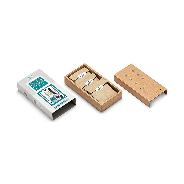
Learn the basics of electronics by assembling manually your Arduino Uno, become familiar with soldering by mounting every single component, and then unleash your creativity with the only kit that becomes a synth!
The Arduino Make-Your-Uno kit is really the best way to learn how to solder. And when you are done, the packaging allows you to build a synth and make your music.
A kit with all the components to build your very own Arduino Uno and audio synthesizer shield.
The Make-Your-Uno kit comes with a complete set of instructions in a dedicated content platform. This includes video material, a 3D interactive viewer for following detailed instructions, and how to program your board once it is finished.
This kit contains:
Arduino Make-Your-Uno
1x Make-Your-Uno PCB
1x USB C Serial adapter Board
7x Resistors 1k Ohm
2x Resistors 10k Ohm
2x Resistors 1M Ohm
1x Diode (1N4007)
1x 16 MHz Crystal
4x Yellow LEDs
1x Green LED
1x Push-Button
1x MOSFET
1x LDO (3.3 V)
1x LDO (5 V)
3x Ceramic capacitors (22pF)
3x Electrolytic capacitors (47uF)
7x Polyester capacitors (100nF)
1x Socket for ATMega 328p
2x I/O Connectors
1x Connector header 6 pins
1x Barrel jack connector
1x ATmega 328p Microcontroller
Arduino Audio Synth
1x Audio Synth PCB
1x Resistor 100k Ohm
1x Resistor 10 Ohm
1x Audio amplifier (LM386)
1x Ceramic capacitors (47nF)
1x Electrolytic capacitors (47uF)
1x Electrolytic capacitors (220uF)
1x Polyester capacitor (100nF)
4x connectors pin header
6x potentiometer 10k Ohm with plastic knobs
Spare parts
2x Electrolytic capacitors (47uF)
2x Polyester capacitor (100nF)
2x Ceramic capacitors (22pF)
1x Push-Button
1x Yellow LEDs
1x Green LED
Mechanical parts
5x Spacers 12 mm
11x Spacers 6 mm
5x screw nuts
2x screws 12 mm
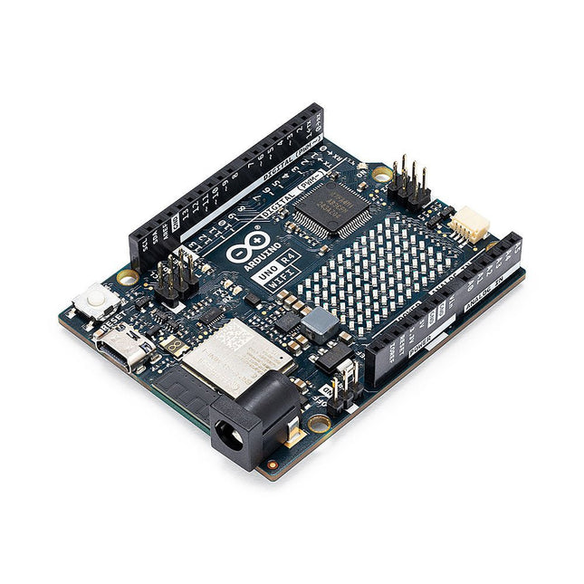
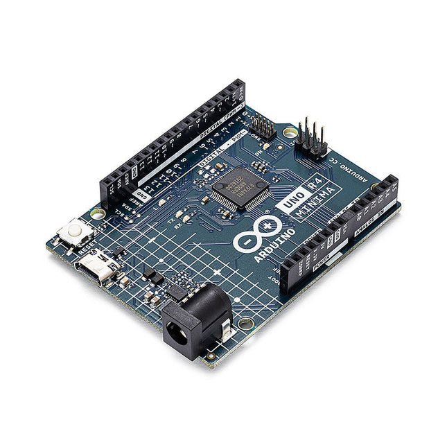
The Arduino Uno R4 is powered by the Renesas RA4M1 32-bit ARM Cortex-M4 processor, providing a significant boost in processing power, memory, and functionality. The WiFi version comes with an ESP32-S3 WiFi module in addition to the RA4M1, expanding creative opportunities for makers and engineers. The Uno R4 Minima is an affordable option for those who don't need the additional features.
The Arduino Uno R4 runs at 48 MHz, which provides a 3x increase over the popular Uno R3. Additionally, SRAM has been upgraded from 2 kB to 32 kB, and flash memory from 32 kB to 256 kB to support more complex projects. Responding to community feedback, the USB port is now USB-C, and the maximum power supply voltage has been raised to 24 V with an enhanced thermal design. The board includes a CAN bus and an SPI port, enabling users to reduce wiring and perform parallel tasks by connecting multiple shields. A 12-bit analog DAC is also provided on the board.
The Arduino Uno R4 comes in 2 versions (Minima and WiFi) and offers the following new features compared to the Uno R3:
Arduino Uno R4 Minima
Arduino Uno R4 WiFi
USB-C connector
USB-C connector
RA4M1 from Renesas (Cortex-M4)
RA4M1 from Renesas (Cortex-M4)
HID device (emulate a mouse or a keyboard)
HID device (emulate a mouse or a keyboard)
Improved power section (up to 24 V through VIN)
Improved power section (up to 24 V through VIN)
CAN bus
CAN bus
DAC (12 bits)
DAC (12 bits)
Op amp
Op amp
WiFi/Bluetooth LE
Fully-addressable LED matrix (12x8)
Qwiic I²C connector
RTC (with support for a buffer battery)
Runtime errors diagnostics
Model Comparison
Uno R3
Uno R4 Minima
Uno R4 WiFi
Microcontroller
Microchip ATmega328P (8-bit AVR RISC)
Renesas RA4M1 (32-bit ARM Cortex-M4)
Renesas RA4M1 (32-bit ARM Cortex-M4)
Operating Voltage
5 V
5 V
5 V
Input Voltage
6-20 V
6-24 V
6-24 V
Digital I/O Pins
14
14
14
PWM Digital I/O Pins
6
6
6
Analog Input Pins
6
6
6
DC Current per I/O Pin
20 mA
8 mA
8 mA
Clock Speed
16 MHz
48 Mhz
48 Mhz
Flash Memory
32 KB
256 KB
256 KB
SRAM
2 KB
32 KB
32 KB
USB
USB-B
USB-C
USB-C
DAC (12 bit)
–
1
1
SPI
1
2
2
I²C
1
2
2
CAN
–
1
1
Op amp
–
1
1
SWD
–
1
1
RTC
–
–
1
Qwiic I²C connector
–
–
1
LED Matrix
–
–
12x8 (96 red LEDs)
LED_BUILTIN
13
13
13
Dimensions
68.6 x 53.4 mm
68.9 x 53.4 mm
68.9 x 53.4 mm
Downloads
Datasheet
Schematics
Add this board to a device and you'll be able to connect it to a WiFi network, using its secure ECC608 crypto chip accelerator. The Arduino Uno WiFi is functionally the same as the Arduino Uno Rev3, but with the addition of WiFi/Bluetooth and some other enhancements. It incorporates the brand new ATmega4809 8-bit microcontroller from Microchip and has an onboard IMU (Inertial Measurement Unit) LSM6DS3TR.
The Wi-Fi Module is a self-contained SoC with an integrated TCP/IP protocol stack that can provide access to a Wi-Fi network, or act as an access point.
The Arduino Uno WiFi Rev2 has 14 digital input/output pins (5 that can be used as PWM outputs, 6 analog inputs), a USB connection, a power jack, an ICSP header, and a reset button. It contains everything needed to support the microcontroller. Simply connect it to a computer with a USB cable or power it with an AC adapter or battery to get started.
Specifications
Operating Voltage
5 V
Input Voltage
7 V - 12 V
Digital I/O
14
Analog Input Pins
6
Analog Input Pins
6
DC Current per I/O Pin
20 mA
DC Current for 3.3 V Pin
50 mA
Flash Memory
48 KB
SRAM
6.144 Bytes
EEPROM
256 Bytes
Clock Speed
16 MHz
Radio Module
u-blox NINA-W102
Secure Element
ATECC608A
Inertial Measurement Unit
LSM6DS3TR
LED_Builtin
25
Length
101.52 mm
Width
53.3 mm
Weight
37 g
The Arduino Uno R4 is powered by the Renesas RA4M1 32-bit ARM Cortex-M4 processor, providing a significant boost in processing power, memory, and functionality. The WiFi version comes with an ESP32-S3 WiFi module in addition to the RA4M1, expanding creative opportunities for makers and engineers. The Uno R4 Minima is an affordable option for those who don't need the additional features.
The Arduino Uno R4 runs at 48 MHz, which provides a 3x increase over the popular Uno R3. Additionally, SRAM has been upgraded from 2 kB to 32 kB, and flash memory from 32 kB to 256 kB to support more complex projects. Responding to community feedback, the USB port is now USB-C, and the maximum power supply voltage has been raised to 24 V with an enhanced thermal design. The board includes a CAN bus and an SPI port, enabling users to reduce wiring and perform parallel tasks by connecting multiple shields. A 12-bit analog DAC is also provided on the board.
The Arduino Uno R4 comes in 2 versions (Minima and WiFi) and offers the following new features compared to the Uno R3:
Arduino Uno R4 Minima
Arduino Uno R4 WiFi
USB-C connector
USB-C connector
RA4M1 from Renesas (Cortex-M4)
RA4M1 from Renesas (Cortex-M4)
HID device (emulate a mouse or a keyboard)
HID device (emulate a mouse or a keyboard)
Improved power section (up to 24 V through VIN)
Improved power section (up to 24 V through VIN)
CAN bus
CAN bus
DAC (12 bits)
DAC (12 bits)
Op amp
Op amp
WiFi/Bluetooth LE
Fully-addressable LED matrix (12x8)
Qwiic I²C connector
RTC (with support for a buffer battery)
Runtime errors diagnostics
Model Comparison
Uno R3
Uno R4 Minima
Uno R4 WiFi
Microcontroller
Microchip ATmega328P (8-bit AVR RISC)
Renesas RA4M1 (32-bit ARM Cortex-M4)
Renesas RA4M1 (32-bit ARM Cortex-M4)
Operating Voltage
5 V
5 V
5 V
Input Voltage
6-20 V
6-24 V
6-24 V
Digital I/O Pins
14
14
14
PWM Digital I/O Pins
6
6
6
Analog Input Pins
6
6
6
DC Current per I/O Pin
20 mA
8 mA
8 mA
Clock Speed
16 MHz
48 Mhz
48 Mhz
Flash Memory
32 KB
256 KB
256 KB
SRAM
2 KB
32 KB
32 KB
USB
USB-B
USB-C
USB-C
DAC (12 bit)
–
1
1
SPI
1
2
2
I²C
1
2
2
CAN
–
1
1
Op amp
–
1
1
SWD
–
1
1
RTC
–
–
1
Qwiic I²C connector
–
–
1
LED Matrix
–
–
12x8 (96 red LEDs)
LED_BUILTIN
13
13
13
Dimensions
68.6 x 53.4 mm
68.9 x 53.4 mm
68.9 x 53.4 mm
Downloads
Datasheet
Schematics
The project book, written by well-known Elektor author Dogan Ibrahim, holds many software- and hardware-based projects especially developed for the Arduino Uno Experimenting Kit. The kit comes with the Arduino Uno R4 Minima, several LEDs, sensors, actuators, and other components. The purpose of the kit is to make a flying start with hardware and software aspects of projects designed around the Arduino Uno microcontroller system.
The projects given in this guide are fully evaluated and working and fully employ all the supplied components. A block diagram, a circuit diagram, an extensive program listing, and a complete program description is given for every project in the guide.
Included
1x Arduino Uno R4 Minima
1x RFID reader module
1x DS1302 clock module
1x 5 V stepper motor
1x '2003' stepper motor drive board
5x Green LED
5x Yellow LED
5x Red LED
2x Rocker switch
1x Flame sensor
1x LM35 sensor module
1x Infrared receiver
3x Light-dependent resistors (LDRs)
1x IR remote controller
1x Breadboard
4x Pushbutton (with four caps)
1x Buzzer
1x Piezo sounder
1x Adjustable resistor (potentiometer)
1x 74HC595 shift register
1x 7-segment display
1x 4-digit 7-segment display
1x 8x8 Dot-matrix display
1x 1602 / I²C LCD module
1x DHT11 Temperature and humidity module
1x Relay module
1x Sound module
Set of Dupont cables
Set of Breadboard cables
1x Water sensor
1x PS2 Joystick
5x 1 k-ohm resistor
5x 10 k-ohm resistor
5x 220-ohm resistor
1x 4x4 keypad module
1x 9g Servo (25 cm)
1x RFID card
1x RGB module
1x 9 V battery DC jack
Project book (326 pages)
Over 80 Projects in the Book
Hardware Projects with LEDs
Blinking LED – using the on-board LED
Blinking LED – using an external LED
LED flashing SOS
Alternately blinking LEDs
Chaser-LEDs
Chasing LEDs 2
Binary counting LEDs
Random flashing LEDs – Christmas lights
Button controlled LED
Controlling the LED flashing rate – external interrupts
Reaction timer
LED color wand
RGB fixed colors
Traffic lights
Traffic lights with pedestrian crossings
Using the 74HC595 shift register – binary up counter
Using the 74HC595 shift register – random flashing 8 LEDs
Using the 74HC595 shift register – chasing LEDs
Using the 74HC595 shift register – turn ON a specified LED
Using the 74HC595 shift register – turn ON specified LEDs
7-Segment LED Displays
7-Segment 1-digit LED counter
7-Segment 4-digit multiplexed LED display
7-Segment 4-digit multiplexed LED display counter – timer interrupts
7-Segment 4-digit multiplexed LED display counter – blanking leading zeroes
7-Segment 4-digit multiplexed LED display – reaction timer
Timer interrupt blinking onboard LED
Liquid Crystal Displays (LCDs)
Display text on the LCD
Scrolling text on the LCD
Display custom characters on the LCD
LCD based conveyor belt goods counter
LCD based accurate clock using timer interrupts
LCD dice
Sensors
Analog temperature sensor
Voltmeter
On/Off temperature controller
Darkness reminder – using a light-dependent resistor (LDR)
Tilt detection
Displaying water level
Water level controller
Water flooding detector with buzzer
Sound detection sensor – control the relay by clapping hands
Flame sensor – fire detection with relay output
Temperature and humidity display
Generating musical tones – melody maker
The RFID Reader
Finding the Tag ID
RFID door lock access with relay
The 4x4 Keypad
Display the pressed key code on the Serial Monitor
Integer calculator with LCD
Keypad door security lock with relay
The Real-Time Clock (RTC) Module
RTC with Serial Monitor
RTC with LCD
Temperature and humidity display with time stamping
Setting and displaying the current time
Periodic interrupt every 2 seconds
The Joystick
Reading analog values from the joystick
8x8 LED Matrix
Displaying shapes
Motors: Servo and Stepper
Test-rotate the servo
Servo sweep
Joystick-controlled servo
Rotate the motor clockwise and then anticlockwise
The Digital to Analog Converter (DAC)
Generating a square wave with 2 V amplitude
Generate a sine wave
Sine wave sweep frequency generator
Generate sine wave whose frequency changes with potentiometer
Generate a square wave with frequency of 1 kHz and amplitude of 1 V
Using the EEPROM, the Human Interface Device, and PWM
Keyboard control to launch Windows programs
LED dimming using PWM
The Arduino Uno R4 WiFi
Using LED matrix 1 – creating a large + shape
Creating images by setting bits
Using LED matrix 2 – creating a large + shape
Animation – displaying a word
Controlling the Arduino Uno R4 WiFi on-board LED from a smartphone using UDP
Serial Communications
Receiving ambient temperature from an Arduino Uno R3
Using an Arduino Uno Simulator
A simple project simulation – flashing LED
Displaying text on LCD
LCD seconds counter
The CAN bus
Arduino Uno R4 WiFi to Arduino Uno R4 Minima CAN bus communication
Sending the temperature readings over the CAN bus
Infrared Receiver and Remote Controller
Decoding the IR remote control codes
Remote relay activation/deactivation
Infrared remote stepper motor control
Programming and Projects for the Minima and WiFi
Based on the low-cost 8-bit ATmega328P processor, the Arduino Uno R3 board is likely to score as the most popular Arduino family member so far, and this workhorse has been with us for many years. Recently, the new Arduino Uno R4 was released, based on a 48-MHz, 32-bit Cortex-M4 processor with a huge amount of SRAM and flash memory. Additionally, a higher-precision ADC and a new DAC are added to the design. The new board also supports the CAN Bus with an interface.
Two versions of the board are available: Uno R4 Minima, and Uno R4 WiFi. This book is about using these new boards to develop many different and interesting projects with just a handful of parts and external modules, which are available as a kit from Elektor. All projects described in the book have been fully tested on the Uno R4 Minima or the Uno R4 WiFi board, as appropriate.
The project topics include the reading, control, and driving of many components and modules in the kit as well as on the relevant Uno R4 board, including
LEDs
7-segment displays (using timer interrupts)
LCDs
Sensors
RFID Reader
4×4 Keypad
Real-time clock (RTC)
Joystick
8×8 LED matrix
Motors
DAC (Digital-to-analog converter)
LED matrix
WiFi connectivity
Serial UART
CAN bus
Infrared controller and receiver
Simulators
… all in creative and educational ways with the project operation and associated software explained in great detail.
The Uno differs from all preceding boards in that it does not use the FTDI USB-to-serial driver chip. Additional features coming with the R3 version are: ATmega16U2 instead of 8U2 as a USB-to-Serial converter. 1.0 pinout: added SDA and SCL pins for TWI communication placed near to the AREF pin and two other new pins placed near to the RESET pin, the IOREF that allow the shields to adapt to the voltage provided from the board and the second one is a not connected pin, that is reserved for future purposes. stronger RESET circuit. Microcontroller ATmega328P Operating Voltage 5 V Input Voltage 7 V - 12 V Digital I/O Pins 14 PWM Pins 6 Analog Input Pins 8 DC Current per I/O Pin 20 mA DC Current for 3.3 V Pin 50 mA Flash Memory 32 KB (ATmega328P) of which 0.5 KB used by bootloader SRAM 2 KB EEPROM 1 KB Clock Speed 16 MHz LED_Builtin 13 Length 68.6 mm Width 53.4 mm Weight 25 g
Celebrating the Arduino Uno with a miniaturized limited edition
The world's favorite development board has gone mini. Everything in this version of the Arduino Uno is unique. Black and gold, finishing, elegant design and packaging, all delivered to the highest standard. A little jewel to celebrate the Arduino community and what we’ve been doing together for all these years.
Each item is unique and numbered on the PCB, and includes a hand-signed letter from the founders. It’s a limited edition, so get while it’s in stock!
For serious Arduino Uno lovers
Arduino Uno Mini Limited Edition is a collector’s item for serious Arduino Lovers: hobbyists, students, makers, reimaginers, dreamers, hopers, fans, engineers, designers, questioners, cake-makers, problem-solvers, puzzlers, gamers, debaters, developers, entrepreneurs, architects, future-shapers, musicians, scientists... 10 million projects based on (official) Uno boards that have contributed to this incredible story.
Specifications
The Arduino Uno Mini Limited Edition is a microcontroller board based on the ATmega328P. It has 14 digital inputs/outputs (six of which can be used as PWM outputs), six analog inputs, a 16 MHz ceramic resonator, a USB-C connector, and a reset button. Contains everything needed to support the microcontroller. Simply connect it to a computer with a USB cable, use a power adapter, or connect a battery to get started.
Microcontroller
ATmega328P
USB connector
USB-C
Built-in LED Pins
13
Digital I/O Pins
14
Analog Input Pins
6
PWM Pins
6
UART
Yes
I²C
Yes
SPI
Yes
Circuit operating voltage
5 V
Input Voltage (limit)
6-12 V
Battery connector
None
DC current per I/O Pin
20 mA
DC current for 3.3 V Pin
50 mA
Main processor
ATmega328P (16 MHz)
USB-serial processor
ATmega16U2 (16 MHz)
Memory ATmega328P
2 KB SRAM, 32 KB Flash, 1 KB EEPROM
Weight
8.05 g
Dimensions
26.70 x 34.20 mm
Downloads
Datasheet