Search results for "smart OR home OR und OR iot OR technik OR fuer OR den OR arduino OR pdf"
-
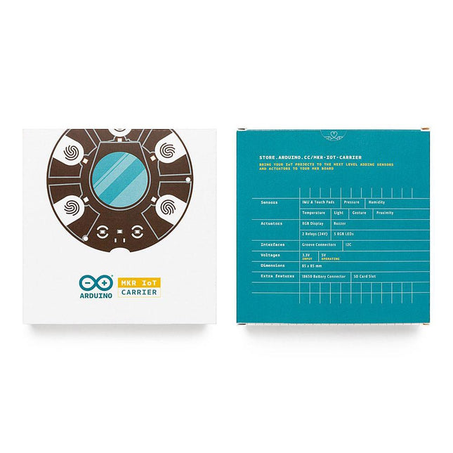
Arduino Arduino MKR IoT Carrier
The MKR IoT Carrier comes equipped with 5 RGB LEDs, 5 capacitive touch buttons, a colored display, IMU and a variety of quality sensors. It also features a battery holder for a 18650 Li-Ion battery, SD card holder and Grove connectors. Data Capture: Map the environment around the carrier using the integrated temperature, humidity, and pressure sensors and collect data about movement using the 6 axis IMU and light, gesture, and proximity sensors. Easily add more external sensors to capture more data from more sources via the on-board Grove connectors (x3). Data Storage: Capture and store all the data locally on an SD card, or connect to the Arduino IoT Cloud for real-time data capture, storage, and visualization. Data Visualisation: Locally view real-time sensor readings on the built-in OLED Color Display and create visual or sound prompts using the embedded LEDs and buzzer. Total Control: Directly control small-voltage electronic appliances using the onboard relays and the five tactile buttons, with the integrated display providing a handy on-device interface for immediate control.
€ 59,95
Members € 53,96
-
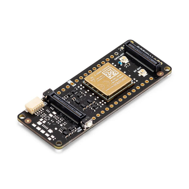
Arduino Arduino Pro Portenta Cat-M1 NB-IoT GNSS Shield
The Arduino Pro Portenta Cat. M1/NB IoT GNSS Shield allows you to enhance the connectivity features of your Portenta H7 applications. The shield leverages a Cinterion TX62 wireless module by Thales, designed for highly efficient, low-power IoT applications to deliver optimized bandwidth and performance. The Portenta Cat. M1/NB IoT GNSS Shield combines with the strong edge computing power of the Portenta H7 to enable the development of asset tracking and remote monitoring applications in industrial settings, as well as in agriculture, public utilities and smart cities. The shield offers cellular connectivity to both Cat. M1 and NB-IoT networks with the option to use eSIM technology. Easily track your valuables – across the city or worldwide – with your choice of GPS, GLONASS, Galileo or BeiDou. Features Change connectivity capabilities without changing the board Add NB-IoT, CAT. M1 and positioning to any Portenta product Possibility to create a small multiprotocol router (WiFi - BT + NB-IoT/CAT. M1) Greatly reduce communication bandwidth requirements in IoT applications Low-power module Compatible also with MKR boards Remote Monitoring Industrial and agricultural companies can leverage the Portenta Cat. M1/NB IoT GNSS Shield to remotely monitor gas detectors, optical sensors, machinery alarm systems, biological bug traps and more. Technology providers providing smart city solutions can compound the power and reliability of the Portenta H7 with the Portenta Cat. M1/NB IoT GNSS Shield, to connect data and automate actions for a truly optimized use of resources and enhanced user experience. Asset Monitoring Add monitoring capabilities to any asset by combining the performance and edge computing features of the Portenta family boards. The Portenta Cat. M1/NB IoT GNSS Shield is ideal to monitor valuable goods and also for monitoring industrial machinery and equipment. Specifications Connectivity Cinterion TX62 wireless module; NB-IoT - LTE CAT.M1; 3GPP Rel.14 Compliant Protocol LTE Cat. M1/NB1/NB2; UMTS BANDS: 1 / 2 / 3 / 4 / 5 / 8 / 12(17) / 13 / 18 / 19 / 20 / 25 / 26 / 27 / 28 / 66 / 71 / 85; LTE Cat.M1 DL: max. 300 kbps, UL: max. 1.1 Mbps; LTE Cat.NB1 DL: max. 27 kbps, UL: max. 63 kbps; LTE Cat.NB2 DL: max. 124 kbps, UL: max. 158 kbps Short messaging service (SMS) Point-to-point mobile terminated (MT) and mobile originated (MO) Text Mode; Protocol Data Unit (PDU) Mode Localization support GNSS capability (GPS/BeiDou/Galileo/GLONASS) Other Embedded IPv4 and IPv6 TCP/IP stack access; Internet Services: TCP server/client, UDP client, DNS, Ping, HTTP client, FTP client, MQTT client Secure Connection with TLS/DTLS Secure boot Dimensions 66 x 25.4 mm Operating temperature -40° C to +85° C (-104° F to 185°F) Downloads Datasheet Schematics
€ 99,95€ 74,95
Members identical
-
Elektor Digital IoT Home Hacks with ESP8266 (E-book)
There are many so-called 'Arduino compatible' platforms on the market. The ESP8266 – in the form of the WeMos D1 Mini Pro – is one that really stands out. This device includes WiFi Internet access and the option of a flash file system using up to 16 MB of external flash memory. Furthermore, there are ample in/output pins (though only one analogue input), PWM, I²C, and one-wire. Needless to say, you are easily able to construct many small IoT devices! This book contains the following builds: A colourful smart home accessory refrigerator controller 230 V power monitor door lock monitor and some further spin-off devices. All builds are documented together with relevant background information for further study. For your convenience, there is a small PCB for most of the designs; you can also use a perf board. You don’t need to be an expert but the minimum recommended essentials include basic experience with a PC, software, and hardware, including the ability to surf the Internet and assemble PCBs. And of course: A handle was kept on development costs. All custom software for the IoT devices and PCB layouts are available for free download from at Elektor.com.
€ 34,95
Members € 27,96
-
Elektor Digital Elektor Arduino Guest Edition 2022 (PDF) EN
Elektor GREEN and GOLD members can download their digital edition here. Not a member yet? Click here. Arduino Portenta Machine Control and Arduino Portenta H7A CAN-to-MQTT Gateway Demo Project Unboxing the Elektor LCR Meter with David Cuartielles MicroPython Enters the World of Arduino Connected Projects, SimplifiedDive Into the Arduino Cloud Introduction to TinyMLBig Is Not Always Better Arduino K-Way Writing Arduino Sketches Just Got Better Get to Know Arduino Getting Started with the Portenta X8Manage Software Securely with Containers Build, Deploy, and Maintain Scalable, Secure ApplicationsWith Arduino Portenta X8 Featuring NXP’s i.MX 8M Mini Applications Processor and EdgeLock SE050 Secure Element How I Automated My HomeArduino CEO Fabio Violante Shares Solutions Altair 8800 SimulatorHardware Simulation of a Vintage Computer MS-DOS on the Portenta H7Run Old-School Software on Contemporary Hardware Grow It YourselfA Digitally Controlled, Single-Box Solution for Indoor Farming Save the Planet With Home Automation?MQTT on the Arduino Nano RP2040 Connect Go Professional with Arduino Pro Smart Ovens Take a Leap Into the Future Tagvance Builds Safer Construction Sites with Arduino Santagostino Breathes Easywith Remote Monitoring that Leverages AI for Predictive Maintenance Security Flies High with RIoT Secure’s MKR-Based Solution Open-Source Brings a New Generation of Water Management to the World SensoDetect Deforestation with Sound Analysis The Mozzi Arduino Library for Sound SynthesisInsights from Tim Barrass The New Portenta X8 (with Linux!) and Max Carrier Redefine What’s Possible How Using Arduino Helps Students Build Future Skills Must-Haves for Your Electronics Workspace The Importance of Robotics in Education Dependable IoT Based Upon LoRa Unboxing the Portenta Machine Control 8-Bit Gaming with Arduboy Reducing Water Usage at Horseback Riding TracksAn IoT to Constantly Monitor Soil Humidity and Temperature Levels The Panettone ProjectA sourdough starter management and maintenance system Supporting Arduino Resellers Space Invaders with Arduino Art with ArduinoInspiring Insights from Artists and Designers Arduino Product Catalogue The Future of Arduino
€ 7,50
-
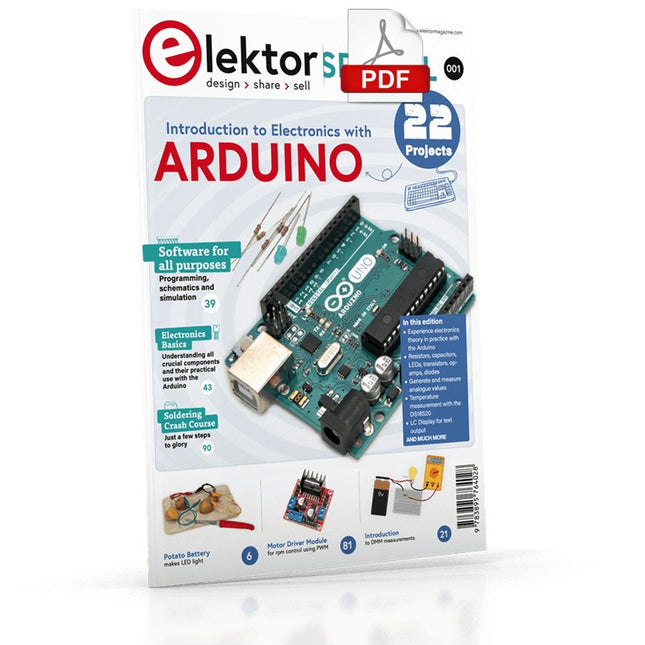
Elektor Digital Elektor Special: Introduction to Electronics with Arduino (PDF)
Although the Arduino isn’t a novelty any longer, there are still many beginners who want to try programming and development with a microcontroller, and to them, it is all new. All beginnings can be difficult, though they should be light and enjoyable. You do not need much or expensive equipment for the examples. The circuits are built on a small breadboard, and, if necessary, connected to an Arduino Uno, which you can program on a Windows PC. You will find clear examples of how to build all circuits, ensuring easy and error-free reproduction. Projects Discussed Current & Voltage – How it all began Arduino Hardware Arduino Programming The Electrical Circuit Measuring with the Multimeter Circuit Diagrams and Breadboards Creating Circuit Diagrams Breadboard Views with Fritzing Online Circuit Simulation Indispensable: Resistors (Part 1) Hands-on with Resistors (Part 2) Variable Resistors Diodes: One-way Street for Current The Transistor Switch Electromagnetism Relays and Motors op-amps: Operational Amplifiers Capacitors The NE555 Timer PWM and Analogue Values with Arduino 7-Segment Temperature Display Introduction to Soldering and LCDs
€ 11,95
-
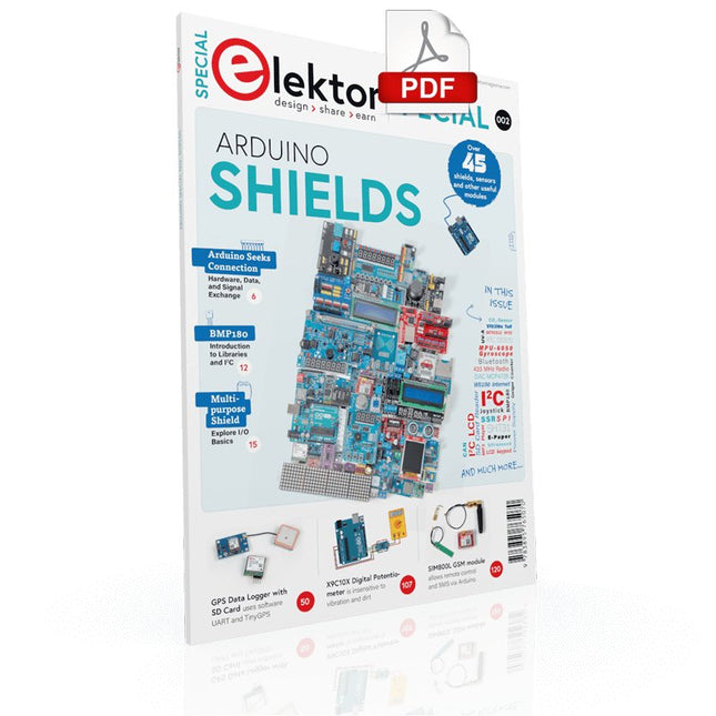
Elektor Digital Elektor Special: Arduino Shields (PDF) EN
Make your project dreams come true: an odometer for the hamster wheel, a fully automatic control of your ant farm with web interface, or the Sandwich-O-Mat – a machine that toasts and grills sandwiches of your choice. With the Arduino and the DIY or Maker movement, not only did entry into microcontroller programming become child's play, but a second development also took place: Resourceful developers brought small boards – so-called shields or modules – to the market, which greatly simplified the use of additional hardware. The small modules contain all the important electronic parts to be connected to the microcontroller with a few plug-in cables, eliminating the need for a fiddly and time-consuming assembly on the plug-in board. In addition, it is also possible to handle tiny components that do not have any connecting legs (so-called SMDs). Projects Discussed Arduino seeks connection BMP and introduction to libraries, I²C Learn I/O basics with the multi-purpose shield I²C LCD adapter and DOT matrix displays LCD keypad shield Level converter W5100: Internet connection I/O expansion shield Relays and solid-state relays The multi-function shield: A universal control unit Connecting an SD card reader via SPI Keys and 7-segment displays 16-bit ADC MCP4725 DAC 16-way PWM servo driver MP3 player GPS data logger using an SD card Touch sensor Joystick SHT31: Temperature and humidity VEML6070 UV-A sensor VL53L0X time-of-flight Ultrasonic distance meter MAX7219-based LED DOT matrix display DS3231 RTC Port expander MCP23017 433 MHz radio MPU-650 gyroscope ADXL345 accelerometer WS2812 RGB LEDs Power supply MQ-xx gas sensors CO2 gas sensor ACS712 current sensor INA219 current sensor L298 motor driver MFRC522 RFID 28BYJ-48 stepper motor TMC2209 silent step stick X9C10x digital potentiometer ST7735 in a color TFT display e-Paper display Bluetooth Geiger counter SIM800L GSM module I²C multiplexer Controller Area Network
€ 11,95
-
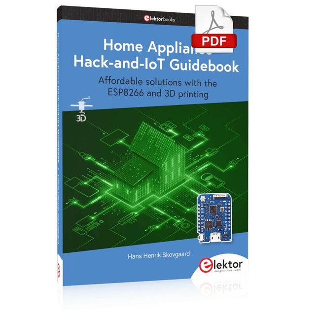
Elektor Digital Home Appliance Hack-and-IoT Guidebook (E-book)
Affordable solutions with the ESP8266 and 3D printing If you are looking for a small yet powerful IoT device, you are likely to come across the ESP8266 and compatible products on the market today. One of these, the Wemos/Lolin D1 Mini Pro board strikes a remarkable balance between cost and performance. A small and very affordable prototype board, the D1 Mini Pro stands out with its WiFi functionality and a 16-Mbytes flash memory for easy creation of a flash file system. In addition, there are sufficient input and output pins (only one analog input though) to support PWM, I²C, and One-Wire systems to mention but a few. The book describes the operation, modding, construction, and programming of home appliances including a colorful smart home accessory, a refrigerator/greenhouse controller, an AC powerline monitor, a door lock monitor, and an IKEA Trådfri controller. As a benefit, all firmware developed for these DIY, "IoT-ized" devices can be updated over-the-air (OTA). For most of the designs in the book, a small printed circuit board (PCB) and an enclosure are presented so readers can have a finished and attractive-looking product. Readers having – or with access to! – a 3D printer can "print" the suggested enclosures at home or in a shop. Some of the constructions benefit from a Raspberry Pi configured as a gateway or cms server. This is also described in detail with all the necessary configuring. You don’t need to be an expert but the prerequisites to successful replication of the projects include basic skills with PC software including the ability to surf the Internet. In terms of hardware, you should be comfortable with soldering and generally assembling the PCBs presented in the book. All custom software written for the IoT devices, the PCB layouts, and 3D print files described in the book are available for free downloading.
€ 34,95
Members € 27,96
-

Elektor Digital Home Automation Projects with Arduino (E-book)
Using the RFID Starter Kit An Arduino board has now become ‘the’ basic component in the maker community. No longer is an introduction to the world of microcontrollers the preserve of the expert. When it comes to expanding the capabilities of the basic Arduino board however, the developer is still largely on his own. If you really want to build some innovative projects it’s often necessary to get down to component level. This can present many beginners with major problems. That is exactly where this book begins. This book explains how a wide variety of practical projects can be built using items supplied in a single kit together with the Arduino board. This kit, called the 'RFID Starter Kit for Arduino' (SKU 17240) is not just limited to RFID applications but contains more than 30 components, devices and modules covering all areas of modern electronics. In addition to more simple components such as LEDs and resistors there are also complex and sophisticated modules that employ the latest technology such as: A humidity sensor A multicolor LED A large LED matrix with 64 points of light A 4-character 7-segment LED display An infra red remote-controller unit A complete LC-display module A servo A stepper motor and controller module A complete RFID reader module and security tag On top of that you will get to build precise digital thermometers, hygrometers, exposure meters and various alarm systems. There are also practical devices and applications such as a fully automatic rain sensor, a sound-controlled remote control system, a multifunctional weather station and so much more. All of the projects described can be built using the components supplied in the Elektor kit.
€ 29,95
Members € 23,96
-
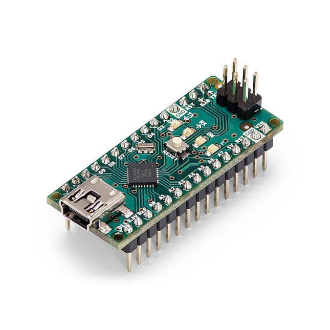
Arduino Arduino Nano
The Arduino Nano is a small, complete, and breadboard-friendly board based on the ATmega328 (Arduino Nano 3.x). It has more or less the same functionality of the Arduino Duemilanove but in a different package. It lacks only a DC power jack and works with a Mini-B USB cable instead of a standard one. Specifications Microcontroller ATmega328 Operating Voltage (logic level) 5 V Input Voltage (recommended) 7-12 V Input Voltage (limits) 6-20 V Digital I/O Pins 14 (of which 6 provide PWM output) Analog Input Pins 8 DC Current per I/O Pin 40 mA Flash Memory 16 KB (ATmega168) or 32 KB (ATmega328) of which 2 KB used by bootloader SRAM 1 KB (ATmega168) or 2 KB (ATmega328) EEPROM 512 bytes (ATmega168) or 1 KB (ATmega328) Clock Speed 16 MHz Dimensions 0.73 x 1.70' (18 x 45 mm) Power The Arduino Nano can be powered via the Mini-B USB connection, 6-20 V unregulated external power supply (pin 30), or 5 V regulated external power supply (pin 27). The power source is automatically selected to the highest voltage source. Memory The ATmega168 has 16 KB of flash memory for storing code (of which 2 KB is used for the bootloader), 1 KB of SRAM and 512 bytes of EEPROM The ATmega328 has 32 KB of flash memory for storing code, (also with 2 KB used for the bootloader), 2 KB of SRAM and 1 KB of EEPROM. Input and Output Each of the 14 digital pins on the Nano can be used as an input or output, using pinMode(), digitalWrite(), and digitalRead() functions. They operate at 5 V. Each pin can provide or receive a maximum of 40 mA and has an internal pull-up resistor (disconnected by default) of 20-50 kOhms. Communication The Arduino Nano has a number of facilities for communicating with a computer, another Arduino, or other microcontrollers. The ATmega168 and ATmega328 provide UART TTL (5V) serial communication, which is available on digital pins 0 (RX) and 1 (TX). An FTDI FT232RL on the board channels this serial communication over USB and the FTDI drivers (included with the Arduino software) provide a virtual com port to software on the computer. The Arduino software includes a serial monitor which allows simple textual data to be sent to and from the Arduino board. The RX and TX LEDs on the board will flash when data is being transmitted via the FTDI chip and USB connection to the computer (but not for serial communication on pins 0 and 1). A SoftwareSerial library allows for serial communication on any of the Nano's digital pins. Programming The Arduino Nano can be programmed with the Arduino software (download). The ATmega168 or ATmega328 on the Arduino Nano comes with a bootloader that allows you to upload new code to it without the use of an external hardware programmer. It communicates using the original STK500 protocol (reference, C header files). You can also bypass the bootloader and program the microcontroller through the ICSP (In-Circuit Serial Programming) header using Arduino ISP or similar; see these instructions for details. Automatic (Software) Reset Rather than requiring a physical press of the reset button before an upload, the Arduino Nano is designed in a way that allows it to be reset by software running on a connected computer. One of the hardware flow control lines (DTR) of theFT232RL is connected to the reset line of the ATmega168 or ATmega328 via a 100 nF capacitor. When this line is asserted (taken low), the reset line drops long enough to reset the chip. The Arduino software uses this capability to allow you to upload code by simply pressing the upload button in the Arduino environment. This means that the bootloader can have a shorter timeout, as the lowering of DTR can be well-coordinated with the start of the upload.
€ 22,95
Members € 20,66
-
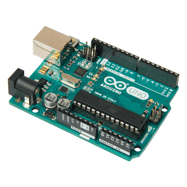
Arduino Arduino Uno Rev3
Arduino Uno is an open-source microcontroller board based on the ATmega328P. It has 14 digital input/output pins (of which 6 can be used as PWM outputs), 6 analog inputs, a 16 MHz ceramic resonator (CSTCE16M0V53-R0), a USB connection, a power jack, an ICSP header and a reset button. It contains everything needed to support the microcontroller; simply connect it to a computer with a USB cable or power it with a AC-to-DC adapter or battery to get started. You can tinker with your Uno without worring too much about doing something wrong, worst case scenario you can replace the chip for a few dollars and start over again. 'Uno' means one in Italian and was chosen to mark the release of Arduino Software (IDE) 1.0. The Uno board and version 1.0 of Arduino Software (IDE) were the reference versions of Arduino, now evolved to newer releases. The Uno board is the first in a series of USB Arduino boards, and the reference model for the Arduino platform; for an extensive list of current, past or outdated boards see the Arduino index of boards. Specifications Microcontroller ATmega328P Operating Voltage 5 V Input Voltage (recommended) 7-12 V Input Voltage (limit) 6-20 V Digital I/O Pins 14 (of which 6 provide PWM output) PWM Digital I/O Pins 6 Analog Input Pins 6 DC Current per I/O Pin 20 mA DC Current for 3.3 V Pin 50 mA Flash Memory 32 KB (ATmega328P) of which 0.5 KB used by bootloader SRAM 2 KB (ATmega328P) EEPROM 1 KB (ATmega328P) Clock Speed 16 MHz LED_BUILTIN 13 Dimensions 68.6 x 53.4 mm Weight 25 g
€ 24,95
Members identical
-
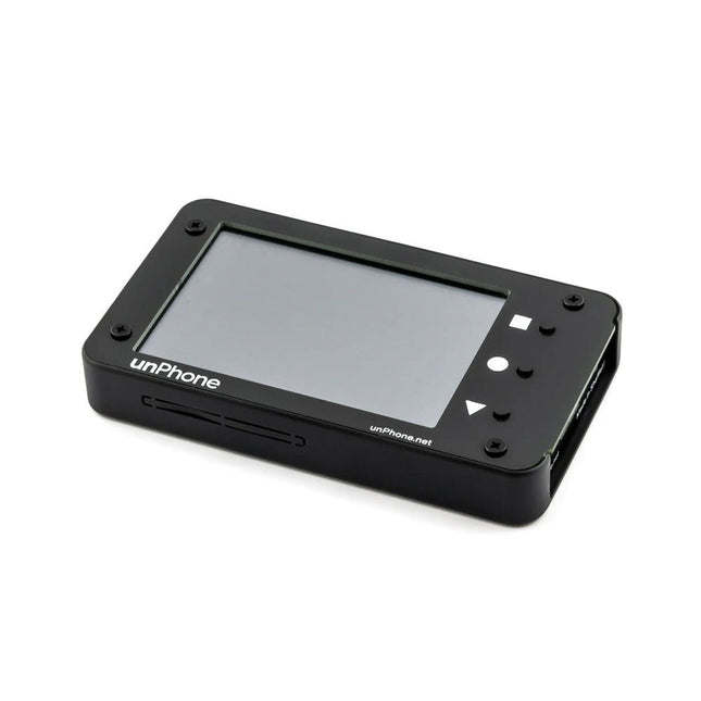
Pimoroni unPhone IoT Development Platform
The unPhone is an open-source IoT development platform powered by the ESP32S3 microcontroller. It features integrated LoRa, Wi-Fi, and Bluetooth connectivity, a touchscreen, and a LiPo battery, offering a robust and versatile solution for IoT development. Its compatibility with Adafruit's FeatherWing standard enables easy expansion, making it an ideal choice for educators, makers, and developers seeking a flexible and user-friendly platform. Features ESP32S3 microcontroller (with 8 MB flash and 8 MB PSRAM) LoRaWAN licence-free radio communication (plus the ESP32's excellent wifi and bluetooth support) 3.5" (320 x 480) LCD capacitive touchscreen for easy debugging and UI creation IR LEDs for surreptitiously switching the cafe TV off 1200 mAh LiPo battery with USB-C charging Vibration motor for notifications Compass/Accelorometer A robust case SD card slot Power and reset buttons Programmable in C++ or CircuitPython Expander board that supports two Featherwing sockets and a prototyping area Open source firmware compatible with the Arduino IDE, PlatformIO and Espressif's IDF development framework Included unPhone (assembled) Expander board FPC cable (to link the expander board to unPhone) Self adhesive mounts for the expander board Code Examples C++ library Kick the tyres on everything in the box The main LVGL demo CircuitPython Support forum Textbook (especially chapter 11)
€ 219,00€ 179,95
Members identical
-

Elektor Publishing Arduino & Co - Measure, Control, and Hack
Clever Tricks with ATmega328 Pro Mini BoardsWith a simple Pro Mini board and a few other components, projects that 20 or 30 years ago were unthinkable (or would have cost a small fortune) are realized easily and affordably in this book: From simple LED effects to a full battery charging and testing station that will put a rechargeable through its paces, there’s something for everyone.All the projects are based on the ATmega328 microcontroller, which offers endless measuring, switching, and control options with its 20 input and output lines. For example, with a 7-segment display and a few resistors, you can build a voltmeter or an NTC-based thermometer. The Arduino platform offers the perfect development environment for programming this range of boards.Besides these very practical projects, the book also provides the necessary knowledge for you to create projects based on your own ideas. How to measure, and what? Which transistor is suitable for switching a certain load? When is it better to use an IC? How do you switch mains voltage? Even LilyPad-based battery-operated projects are discussed in detail, as well as many different motors, from simple DC motors to stepper motors.Sensors are another exciting topic: For example, a simple infrared receiver that can give disused remote controls a new lease on life controlling your home, and a tiny component that can actually measure the difference in air pressure between floor and table height!
€ 39,95
Members € 35,96


