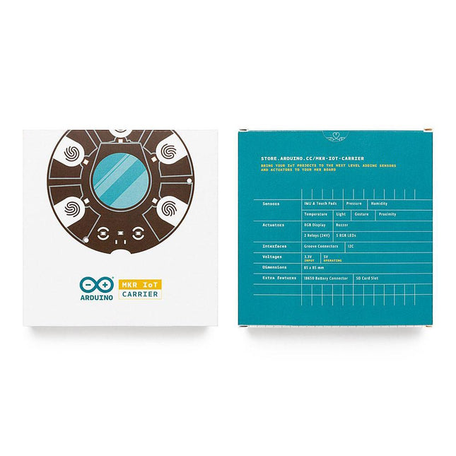
The MKR IoT Carrier comes equipped with 5 RGB LEDs, 5 capacitive touch buttons, a colored display, IMU and a variety of quality sensors. It also features a battery holder for a 18650 Li-Ion battery, SD card holder and Grove connectors.
Data Capture: Map the environment around the carrier using the integrated temperature, humidity, and pressure sensors and collect data about movement using the 6 axis IMU and light, gesture, and proximity sensors. Easily add more external sensors to capture more data from more sources via the on-board Grove connectors (x3).
Data Storage: Capture and store all the data locally on an SD card, or connect to the Arduino IoT Cloud for real-time data capture, storage, and visualization.
Data Visualisation: Locally view real-time sensor readings on the built-in OLED Color Display and create visual or sound prompts using the embedded LEDs and buzzer.
Total Control: Directly control small-voltage electronic appliances using the onboard relays and the five tactile buttons, with the integrated display providing a handy on-device interface for immediate control.
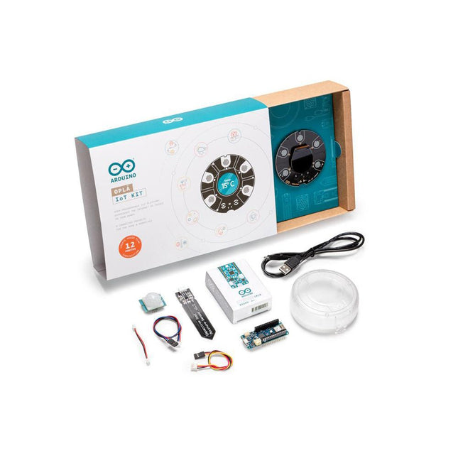
The Oplà IoT Kit allows you to add connectivity to devices around the home or workplace. It comes complete with a set of 8 Internet of Things self-assemble projects ready to show you how to turn everyday appliances into ‘smart appliances’ and build custom connected devices that can be controlled with your mobile phone.
Features
Remote Controlled Lights - change color, light modes and switch on/off via your mobile
Personal Weather Station - record and monitor local weather conditions
Home Security Alarm - Detect motions and trigger warnings
Solar System Tracker - retrieve data from planets and moons in the Solar System
Inventory Control - track goods in & out
Smart Garden - monitor and control the environment for your plants
Thermostat Control - smart control for heating and cooling systems
Thinking About You - send messages between the Oplà and the Arduino IoT Cloud
For more advanced users the kit provides them with the potential to create their own connected devices and IoT applications through the open programmable platform providing the ultimate control.
The Oplà unit acts as the physical interface with the Arduino IoT Cloud providing you with total control at your fingertips via the Arduino IoT Remote app. Configure and manage all the settings via the Arduino IoT Cloud, with easy to create dashboards providing real-time readings from your smart devices around the home or workplace.
Adjusting settings, switching devices on/off, watering plants, etc are all controllable on the go with the Arduino IoT Remote app or fully automate the set-up then sit back and enjoy!
Applications
Remote Controlled Lights
Personal Weather Station
Home Security Alarm
Solar System Tracker
Inventory Control
Smart Garden
Thermostat Control
Thinking About You
Included
MKR IoT Carrier designed for this kit, including:
Round OLED Display
Five capacitive touch buttons
On-board sensors (temperature, humidity, pressure, and light)
Two 24 V relays
SD card holder
Plug and play connectors for different sensors
RGBC, Gesture, and Proximity
IMU
18650 Li-Ion rechargeable battery holder (battery not included)
Five RGB LEDs
Arduino MKR WiFi 1010
Plastic encasing
Micro USB cable
Moisture sensor
PIR sensor
Plug-and-play cables for all the sensors
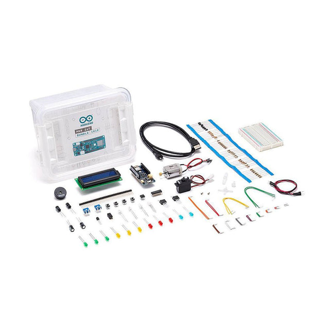
The best way to start exploring the world of connected devices using the Arduino MKR WiFi 1010. The MKR IoT bundle contains all you need to build your first connected devices. Follow the 5 step by step tutorials we have prepared for you and combining the electronic components included in the bundle, you’ll quickly learn how to build devices that connect to the Arduino IoT cloud. All you need to start with IoT This bundle is contains all the hardware and software required to build your first IoT devices with no extra fees. Build 5 IoT projects All the components needed to start your journey into building your own IoT projects. Learn about the Arduino IoT cloud Not only learn about electronic but also about the possibilities the Arduino IoT cloud can offer. Included 1x Arduino MKR1000 WiFi (with mounted headers) 6x Phototransistors 1x Tilt Sensor 1x Temperature sensor (TMP36) 3x Potentiometer 1x Piezo capsule 10x Pushbuttons 1x DC Motor 1x Small servo motor 1x Alphanumeric LCD (16x2 characters) 1x Optocouplers (4N35) 1x H-bridge motor driver (L293D) 2x Mosfet transistors (IRF520) 5x Capacitors 100uF 70x Solid core jumper wires 1x Micro USB cable 1x Breadboard 1x LED (bright white) 3x LEDs (blue) 1x LED (RGB) 8x LED 5 mm (red) 8x LED 5 mm (green) 8x LED 5 mm (yellow) 1x Male pins strip (4x1) 1x Stranded jumper wires (red) 1x Stranded jumper wires (black) 5x Diode 20x 220 Ω resistors 5x 560 Ω resistors 5x 1 KΩ resistors 5x 4.7 KΩ resistors 20x 10 KΩ resistors 5x 1 MΩ resistors 5x 10 MΩ resistors
The board's main processor is a low-power Arm® Cortex®-M0 32-bit SAMD21. The WiFi and Bluetooth® connectivity is performed with a module from u-blox, the NINA-W10, a low-power chipset operating in the 2.4GHz range. On top of that, secure communication is ensured through the Microchip® ECC608 crypto chip. Besides that, you can find a 6 axis IMU, which makes this board perfect for simple vibration alarm systems, pedometers, the relative positioning of robots, etc. WiFi and Arduino IoT Cloud You can get your board to connect to any kind of existing WiFi network, or use it to create your own Arduino Access Point. The specific set of examples we provide for the Nano 33 IoT can be consulted at the WiFiNINA library reference page. It is also possible to connect your board to different Cloud services, Arduino's own among others. Here are some examples of how to get the Arduino boards to connect to:
Arduino's own IoT Cloud: Arduino's IoT Cloud is a simple and fast way to ensure secure communication for all of your connected Things. Check it out here.
Blynk: a simple project from our community connecting to Blynk to operate your board from a phone with little code.
IFTTT: see an in-depth case of building a smart plug connected to IFTTT.
AWS IoT Core: we made this example on how to connect to Amazon Web Services.
Azure: visit this GitHub repository explaining how to connect a temperature sensor to Azure's Cloud.
Firebase: you want to connect to Google's Firebase, this Arduino library will show you how. Microcontroller SAMD21 Cortex®-M0+ 32bit low power ARM MCU Radio Module u-blox NINA-W102 Secure Element ATECC608A Operating Voltage 3.3 V Input Voltage 21 V Digital I/O Pins 14 PWM Pins 11 DC Current per I/O Pin 7 mA Analog Input Pins 8 Analog Output Pins 1 External Interrupts all digital pins UART 1 SPI 1 I2C 1 Flash Memory 256 KB SRAM 32 KB EEPROM none Clock Speed 48 MHz LED_Builtin 13 USB Native in the SAMD21 Processor IMU LSM6DS3 Length 45 mm Width 18 mm Weight 5 g
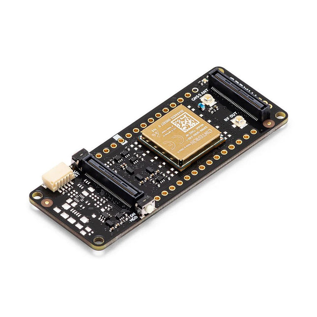
The Arduino Pro Portenta Cat. M1/NB IoT GNSS Shield allows you to enhance the connectivity features of your Portenta H7 applications. The shield leverages a Cinterion TX62 wireless module by Thales, designed for highly efficient, low-power IoT applications to deliver optimized bandwidth and performance.
The Portenta Cat. M1/NB IoT GNSS Shield combines with the strong edge computing power of the Portenta H7 to enable the development of asset tracking and remote monitoring applications in industrial settings, as well as in agriculture, public utilities and smart cities. The shield offers cellular connectivity to both Cat. M1 and NB-IoT networks with the option to use eSIM technology. Easily track your valuables – across the city or worldwide – with your choice of GPS, GLONASS, Galileo or BeiDou.
Features
Change connectivity capabilities without changing the board
Add NB-IoT, CAT. M1 and positioning to any Portenta product
Possibility to create a small multiprotocol router (WiFi - BT + NB-IoT/CAT. M1)
Greatly reduce communication bandwidth requirements in IoT applications
Low-power module
Compatible also with MKR boards
Remote Monitoring
Industrial and agricultural companies can leverage the Portenta Cat. M1/NB IoT GNSS Shield to remotely monitor gas detectors, optical sensors, machinery alarm systems, biological bug traps and more.
Technology providers providing smart city solutions can compound the power and reliability of the Portenta H7 with the Portenta Cat. M1/NB IoT GNSS Shield, to connect data and automate actions for a truly optimized use of resources and enhanced user experience.
Asset Monitoring
Add monitoring capabilities to any asset by combining the performance and edge computing features of the Portenta family boards. The Portenta Cat. M1/NB IoT GNSS Shield is ideal to monitor valuable goods and also for monitoring industrial machinery and equipment.
Specifications
Connectivity
Cinterion TX62 wireless module; NB-IoT - LTE CAT.M1; 3GPP Rel.14 Compliant Protocol LTE Cat. M1/NB1/NB2; UMTS BANDS: 1 / 2 / 3 / 4 / 5 / 8 / 12(17) / 13 / 18 / 19 / 20 / 25 / 26 / 27 / 28 / 66 / 71 / 85; LTE Cat.M1 DL: max. 300 kbps, UL: max. 1.1 Mbps; LTE Cat.NB1 DL: max. 27 kbps, UL: max. 63 kbps; LTE Cat.NB2 DL: max. 124 kbps, UL: max. 158 kbps
Short messaging service (SMS)
Point-to-point mobile terminated (MT) and mobile originated (MO) Text Mode; Protocol Data Unit (PDU) Mode
Localization support
GNSS capability (GPS/BeiDou/Galileo/GLONASS)
Other
Embedded IPv4 and IPv6 TCP/IP stack access; Internet Services: TCP server/client, UDP client, DNS, Ping, HTTP client, FTP client, MQTT client Secure Connection with TLS/DTLS Secure boot
Dimensions
66 x 25.4 mm
Operating temperature
-40° C to +85° C (-104° F to 185°F)
Downloads
Datasheet
Schematics
There are many so-called 'Arduino compatible' platforms on the market. The ESP8266 – in the form of the WeMos D1 Mini Pro – is one that really stands out. This device includes WiFi Internet access and the option of a flash file system using up to 16 MB of external flash memory. Furthermore, there are ample in/output pins (though only one analogue input), PWM, I²C, and one-wire. Needless to say, you are easily able to construct many small IoT devices!
This book contains the following builds:
A colourful smart home accessory
refrigerator controller
230 V power monitor
door lock monitor
and some further spin-off devices.
All builds are documented together with relevant background information for further study. For your convenience, there is a small PCB for most of the designs; you can also use a perf board. You don’t need to be an expert but the minimum recommended essentials include basic experience with a PC, software, and hardware, including the ability to surf the Internet and assemble PCBs.
And of course: A handle was kept on development costs. All custom software for the IoT devices and PCB layouts are available for free download from at Elektor.com.
Affordable solutions with the ESP8266 and 3D printing
If you are looking for a small yet powerful IoT device, you are likely to come across the ESP8266 and compatible products on the market today. One of these, the Wemos/Lolin D1 Mini Pro board strikes a remarkable balance between cost and performance. A small and very affordable prototype board, the D1 Mini Pro stands out with its WiFi functionality and a 16-Mbytes flash memory for easy creation of a flash file system. In addition, there are sufficient input and output pins (only one analog input though) to support PWM, I²C, and One-Wire systems to mention but a few. The book describes the operation, modding, construction, and programming of home appliances including a colorful smart home accessory, a refrigerator/greenhouse controller, an AC powerline monitor, a door lock monitor, and an IKEA Trådfri controller.
As a benefit, all firmware developed for these DIY, "IoT-ized" devices can be updated over-the-air (OTA).
For most of the designs in the book, a small printed circuit board (PCB) and an enclosure are presented so readers can have a finished and attractive-looking product. Readers having – or with access to! – a 3D printer can "print" the suggested enclosures at home or in a shop.
Some of the constructions benefit from a Raspberry Pi configured as a gateway or cms server. This is also described in detail with all the necessary configuring.
You don’t need to be an expert but the prerequisites to successful replication of the projects include basic skills with PC software including the ability to surf the Internet. In terms of hardware, you should be comfortable with soldering and generally assembling the PCBs presented in the book.
All custom software written for the IoT devices, the PCB layouts, and 3D print files described in the book are available for free downloading.
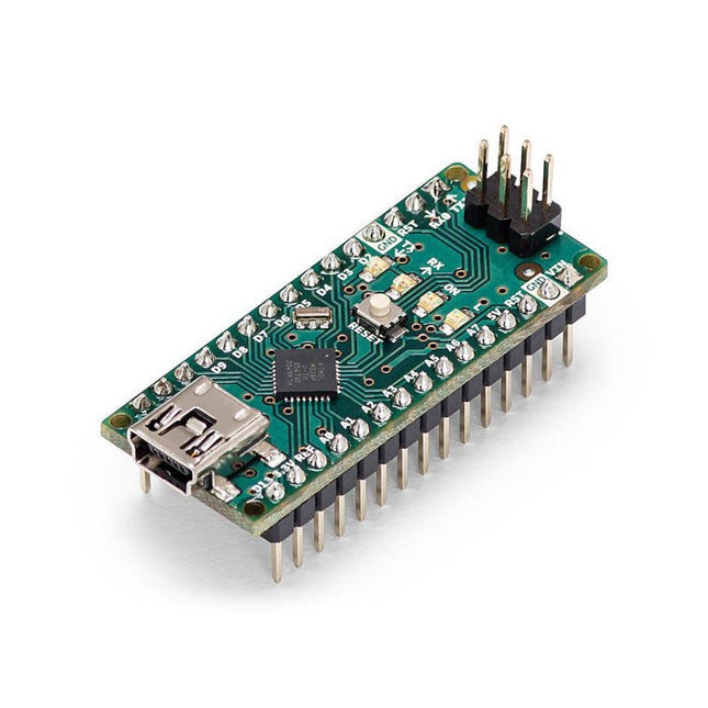
The Arduino Nano is a small, complete, and breadboard-friendly board based on the ATmega328 (Arduino Nano 3.x). It has more or less the same functionality of the Arduino Duemilanove but in a different package. It lacks only a DC power jack and works with a Mini-B USB cable instead of a standard one.
Specifications
Microcontroller
ATmega328
Operating Voltage (logic level)
5 V
Input Voltage (recommended)
7-12 V
Input Voltage (limits)
6-20 V
Digital I/O Pins
14 (of which 6 provide PWM output)
Analog Input Pins
8
DC Current per I/O Pin
40 mA
Flash Memory
16 KB (ATmega168) or 32 KB (ATmega328) of which 2 KB used by bootloader
SRAM
1 KB (ATmega168) or 2 KB (ATmega328)
EEPROM
512 bytes (ATmega168) or 1 KB (ATmega328)
Clock Speed
16 MHz
Dimensions
0.73 x 1.70' (18 x 45 mm)
Power
The Arduino Nano can be powered via the Mini-B USB connection, 6-20 V unregulated external power supply (pin 30), or 5 V regulated external power supply (pin 27). The power source is automatically selected to the highest voltage source.
Memory
The ATmega168 has 16 KB of flash memory for storing code (of which 2 KB is used for the bootloader), 1 KB of SRAM and 512 bytes of EEPROM
The ATmega328 has 32 KB of flash memory for storing code, (also with 2 KB used for the bootloader), 2 KB of SRAM and 1 KB of EEPROM.
Input and Output
Each of the 14 digital pins on the Nano can be used as an input or output, using pinMode(), digitalWrite(), and digitalRead() functions. They operate at 5 V.
Each pin can provide or receive a maximum of 40 mA and has an internal pull-up resistor (disconnected by default) of 20-50 kOhms.
Communication
The Arduino Nano has a number of facilities for communicating with a computer, another Arduino, or other microcontrollers.
The ATmega168 and ATmega328 provide UART TTL (5V) serial communication, which is available on digital pins 0 (RX) and 1 (TX). An FTDI FT232RL on the board channels this serial communication over USB and the FTDI drivers (included with the Arduino software) provide a virtual com port to software on the computer.
The Arduino software includes a serial monitor which allows simple textual data to be sent to and from the Arduino board. The RX and TX LEDs on the board will flash when data is being transmitted via the FTDI chip and USB connection to the computer (but not for serial communication on pins 0 and 1).
A SoftwareSerial library allows for serial communication on any of the Nano's digital pins.
Programming
The Arduino Nano can be programmed with the Arduino software (download).
The ATmega168 or ATmega328 on the Arduino Nano comes with a bootloader that allows you to upload new code to it without the use of an external hardware programmer. It communicates using the original STK500 protocol (reference, C header files).
You can also bypass the bootloader and program the microcontroller through the ICSP (In-Circuit Serial Programming) header using Arduino ISP or similar; see these instructions for details.
Automatic (Software) Reset
Rather than requiring a physical press of the reset button before an upload, the Arduino Nano is designed in a way that allows it to be reset by software running on a connected computer.
One of the hardware flow control lines (DTR) of theFT232RL is connected to the reset line of the ATmega168 or ATmega328 via a 100 nF capacitor. When this line is asserted (taken low), the reset line drops long enough to reset the chip.
The Arduino software uses this capability to allow you to upload code by simply pressing the upload button in the Arduino environment. This means that the bootloader can have a shorter timeout, as the lowering of DTR can be well-coordinated with the start of the upload.
Using the RFID Starter Kit
An Arduino board has now become ‘the’ basic component in the maker community. No longer is an introduction to the world of microcontrollers the preserve of the expert. When it comes to expanding the capabilities of the basic Arduino board however, the developer is still largely on his own. If you really want to build some innovative projects it’s often necessary to get down to component level. This can present many beginners with major problems. That is exactly where this book begins.
This book explains how a wide variety of practical projects can be built using items supplied in a single kit together with the Arduino board. This kit, called the 'RFID Starter Kit for Arduino' (SKU 17240) is not just limited to RFID applications but contains more than 30 components, devices and modules covering all areas of modern electronics.
In addition to more simple components such as LEDs and resistors there are also complex and sophisticated modules that employ the latest technology such as:
A humidity sensor
A multicolor LED
A large LED matrix with 64 points of light
A 4-character 7-segment LED display
An infra red remote-controller unit
A complete LC-display module
A servo
A stepper motor and controller module
A complete RFID reader module and security tag
On top of that you will get to build precise digital thermometers, hygrometers, exposure meters and various alarm systems. There are also practical devices and applications such as a fully automatic rain sensor, a sound-controlled remote control system, a multifunctional weather station and so much more.
All of the projects described can be built using the components supplied in the Elektor kit.
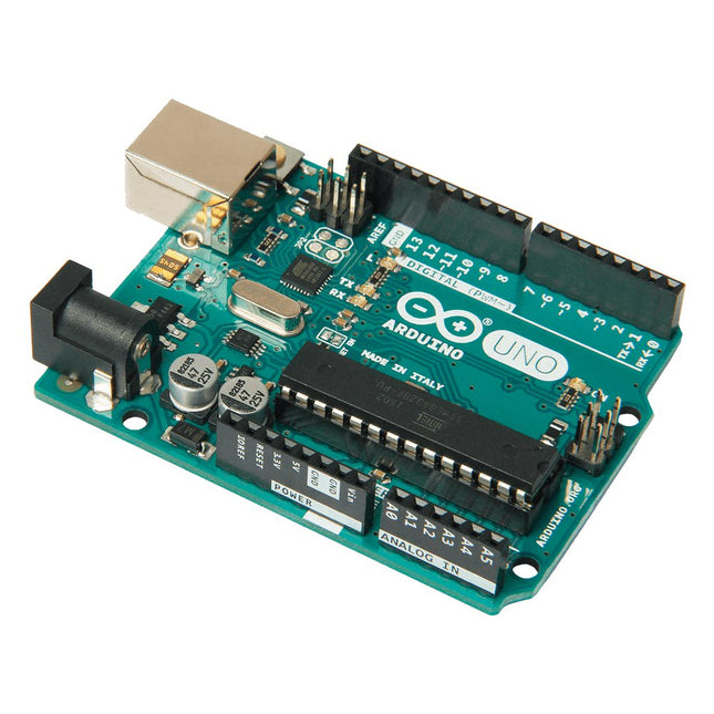
Arduino Uno is an open-source microcontroller board based on the ATmega328P. It has 14 digital input/output pins (of which 6 can be used as PWM outputs), 6 analog inputs, a 16 MHz ceramic resonator (CSTCE16M0V53-R0), a USB connection, a power jack, an ICSP header and a reset button. It contains everything needed to support the microcontroller; simply connect it to a computer with a USB cable or power it with a AC-to-DC adapter or battery to get started. You can tinker with your Uno without worring too much about doing something wrong, worst case scenario you can replace the chip for a few dollars and start over again.
'Uno' means one in Italian and was chosen to mark the release of Arduino Software (IDE) 1.0. The Uno board and version 1.0 of Arduino Software (IDE) were the reference versions of Arduino, now evolved to newer releases. The Uno board is the first in a series of USB Arduino boards, and the reference model for the Arduino platform; for an extensive list of current, past or outdated boards see the Arduino index of boards.
Specifications
Microcontroller
ATmega328P
Operating Voltage
5 V
Input Voltage (recommended)
7-12 V
Input Voltage (limit)
6-20 V
Digital I/O Pins
14 (of which 6 provide PWM output)
PWM Digital I/O Pins
6
Analog Input Pins
6
DC Current per I/O Pin
20 mA
DC Current for 3.3 V Pin
50 mA
Flash Memory
32 KB (ATmega328P) of which 0.5 KB used by bootloader
SRAM
2 KB (ATmega328P)
EEPROM
1 KB (ATmega328P)
Clock Speed
16 MHz
LED_BUILTIN
13
Dimensions
68.6 x 53.4 mm
Weight
25 g
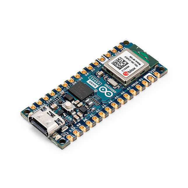
The Arduino Nano ESP32 (with and without headers) is a Nano form factor board based on the ESP32-S3 (embedded in the NORA-W106-10B from u-blox). This is the first Arduino board to be based fully on an ESP32, and features Wi-Fi, Bluetooth LE, debugging via native USB in the Arduino IDE as well as low power. The Nano ESP32 is compatible with the Arduino IoT Cloud, and has support for MicroPython. It is an ideal board for getting started with IoT development. Features
Tiny footprint: Designed with the well-known Nano form factor in mind, this board's compact size makes it perfect for embedding in standalone projects.
Wi-Fi and Bluetooth: Harness the power of the ESP32-S3 microcontroller, well-known in the IoT realm, with full Arduino support for wireless and Bluetooth connectivity.
Arduino and MicroPython support: Seamlessly switch between Arduino and MicroPython programming with a few simple steps.
Arduino IoT Cloud compatible: Quickly and easily create IoT projects with just a few lines of code. The setup takes care of security, allowing you to monitor and control your project from anywhere using the Arduino IoT Cloud app.
HID support: Simulate human interface devices, such as keyboards or mice, over USB, opening up new possibilities for interacting with your computer. Specifications Microcontroller u-blox NORA-W106 (ESP32-S3) USB connector USB-C Pins Built-in LED pins 13 Built-in RGB LED pins 14-16 Digital I/O pins 14 Analog input pins 8 PWM pins 5 External interrupts All digital pins Connectivity Wi-Fi u-blox NORA-W106 (ESP32-S3) Bluetooth u-blox NORA-W106 (ESP32-S3) Communication UART 2x I²C 1x, A4 (SDA), A5 (SCL) SPI D11 (COPI), D12 (CIPO), D13 (SCK). Use any GPIO for Chip Select (CS) Power I/O Voltage 3.3 V Input voltage (nominal) 6-21 V Source Current per I/O pin 40 mA Sink Current per I/O pin 28 mA Clock speed Processor Up to 240 MHz Memory ROM 384 kB SRAM 512 kB External Flash 128 Mbit (16 MB) Dimensions 18 x 45 mm Downloads Datasheet Schematics
The Elektor MultiCalculator Kit is an Arduino-based multifunction calculator that goes beyond basic calculations. It offers 22 functions including light and temperature measurement, differential temperature analysis, and NEC IR remote control decoding. The Elektor MultiCalculator is a handy tool for use in your projects or for educational purposes.
The kit features a Pro Mini module as the computing unit. The PCB is easy to assemble using through-hole components. The enclosure consists of 11 acrylic panels and mounting materials for easy assembly. Additionally, the device is equipped with a 16x2 alphanumeric LCD, 20 buttons, and temperature sensors.
The Elektor MultiCalculator is programmable with the Arduino IDE through a 6-way PCB header. The available software is bilingual (English and Dutch). The calculator can be programmed with a programming adapter, and it is powered through USB-C.
Modes of Operation
Calculator
4-Ring Resistor Code
5-Ring Resistor Code
Decimal to Hexadecimal and Character (ASCII) conversion
Hexadecimal to Decimal and Character (ASCII) conversion
Decimal to Binary and Character (ASCII) conversion
Binary to Decimal and Hexadecimal conversion
Hz, nF, capacitive reactance (XC) calculation
Hz, µH, inductive reactance (XL) calculation
Resistance calculation of two resistors connected in parallel
Resistance calculation of two resistors connected in series
Calculation of unknown parallel resistor
Temperature measurement
Differential temperature measurement T1&T2 and Delta (δ)
Light measurement
Stopwatch with lap time function
Item counter
NEC IR remote control decoding
AWG conversion (American Wire Gauge)
Rolling Dice
Personalize startup message
Temperature calibration
Specifications
Menu languages: English, Dutch
Dimensions: 92 x 138 x 40 mm
Build time: approx. 5 hours
Included
PCB and though-hole components
Precut acrylic sheets with all mechanical parts
Pro Mini microcontroller module (ATmega328/5 V/16 MHz)
Programming adapter
Waterproof temperature sensors
USB-C cable
Downloads
Software