The CubeCell series is designed primarily for LoRa/LoRaWAN node applications.
Built on the ASR605x platform (ASR6501, ASR6502), these chips integrate the PSoC 4000 series MCU (ARM Cortex-M0+ Core) with the SX1262 module. The CubeCell series offers seamless Arduino compatibility, stable LoRaWAN protocol operation, and straightforward connectivity with lithium batteries and solar panels.
The HTCC-AB02S is a developer-friendly board with an integrated AIR530Z GPS module, ideal for quickly testing and validating communication solutions.
Features
Arduino compatible
Based on ASR605x (ASR6501, ASR6502), those chips are already integrated the PSoC 4000 series MCU (ARM Cortex M0+ Core) and SX1262
LoRaWAN 1.0.2 support
Ultra low power design, 21 uA in deep sleep
Onboard SH1.25-2 battery interface, integrated lithium battery management system (charge and discharge management, overcharge protection, battery power detection, USB/battery power automatic switching)
Good impendence matching and long communication distance
Onboard solar energy management system, can directly connect with a 5.5~7 V solar panel
Micro USB interface with complete ESD protection, short circuit protection, RF shielding, and other protection measures
Integrated CP2102 USB to serial port chip, convenient for program downloading, debugging information printing
Onboard 0.96-inch 128x64 dot matrix OLED display, which can be used to display debugging information, battery power, and other information
Using Air530 GPS module with GPS/Beidou Dual-mode position system support
Specifications
Main Chip
ASR6502 (48 MHz ARM Cortex-M0+ MCU)
LoRa Chipset
SX1262
Frequency
863~870 MHz
Max. TX Power
22 ±1 dBm
Max. Receiving Sensitivity
−135 dBm
Hardware Resource
2x UART1x SPI2x I²C1x SWD3x 12-bit ADC input8-channel DMA engine16x GPIO
Memory
128 Kb FLASH16 Kb SRAM
Power consumption
Deep sleep 21 uA
Interfaces
1x Micro USB1x LoRa Antenna (IPEX)2x (15x 2.54 Pin header) + 3x (2x 2.54 Pin header)
Battery
3.7 V lithium battery (power supply and charging)
Solar Energy
VS pin can be connected to 5.5~7 V solar panel
USB to Serial Chip
CP2102
Display
0.96" OLED (128 x 64)
Operating temperature
−20~70°C
Dimensions
55.9 x 27.9 x 9.5 mm
Included
1x CubeCell HTCC-AB02S Development Board
1x Antenna
1x 2x SH1.25 battery connector
Downloads
Datasheet
Schematic
GPS module (Manual)
Quick start
GitHub
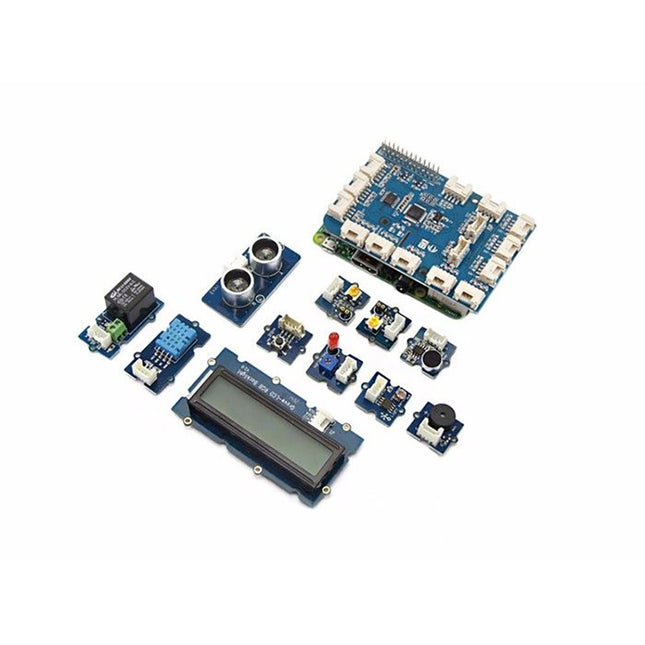
The GrovePi+ is an easy-to-use and modular system for hardware hacking with the Raspberry Pi, no need for soldering or breadboards: plug in your Grove sensors and start programming directly.
Grove is an easy-to-use collection of more than 100 inexpensive plug-and-play modules that sense and control the physical world. By connecting Grove Sensors to Raspberry Pi, it empowers your Pi in the physical world. With hundreds of sensors to choose from Grove families, the possibilities for interaction are endless.
Set-up in 4 simple steps
Slip the GrovePi+ board over your Raspberry Pi
Connect the Grove modules to the GrovePi+ board
Upload your program to Raspberry Pi
Begin taking in the world data
GrovePi+ is stacked on top of the Raspberry Pi without the need for any other connections. Communication between the two occurs over the I²C interface. All Grove modules connect to the universal Grove connectors on the GrovePi+ shield via the universal 4-pin connector cable.
Grove modules work on analog and digital signals and can be connected directly to the ATMEGA328 microcontroller on the Grove Pi+. The microcontroller acts as an interpreter between the Raspberry Pi and the Grove sensors. It sends, receives, and executes commands sent by the Raspberry Pi.
Features
One GrovePi+ board together with 12 popular Grove sensors and 10 Grove cables
GrovePi+ is compatible with Raspberry Pi A+, B, B+ / 2, 3, 4.
CE certified and compatible with Linux and Win 10 IoT.
Included
1x Grove Pi+
1x Grove - Rotary Angle Sensor
1x Grove - Sound Sensor
1x Grove - LCD RGB Backlight
1x Grove - Temp&Humi Sensor
1x Grove - Red LED
1x Grove - Light Sensor
1x Grove - Buzzer
1x Grove - Relay
1x Grove - Blue LED
1x Grove - Button
1x GrovePi+ Guidebook
10x Cables
1x Grove - UItrasonic Ranger
1x Grove - Green LED
Features Integrated Cold-Junction Compensation Supported Types (designated by NIST ITS-90): Type K, J, T, N, S, E, B and R Four Programmable Temperature Alert Outputs: Monitor Hot- or Cold-Junction Temperatures Detect rising or falling temperatures Up to 255°C of Programmable Hysteresis Programmable Digital Filter for Temperature Low Power Dimensions: 20 mm x 40 mm x 18 mm Weight: 18 g Application Petrochemical Thermal Management Hand-Held Measurement Equipment Industrial Equipment Thermal Management Ovens Industrial Engine Thermal Monitor Temperature Detection Racks Downloads Eagle Files Github library Datasheet
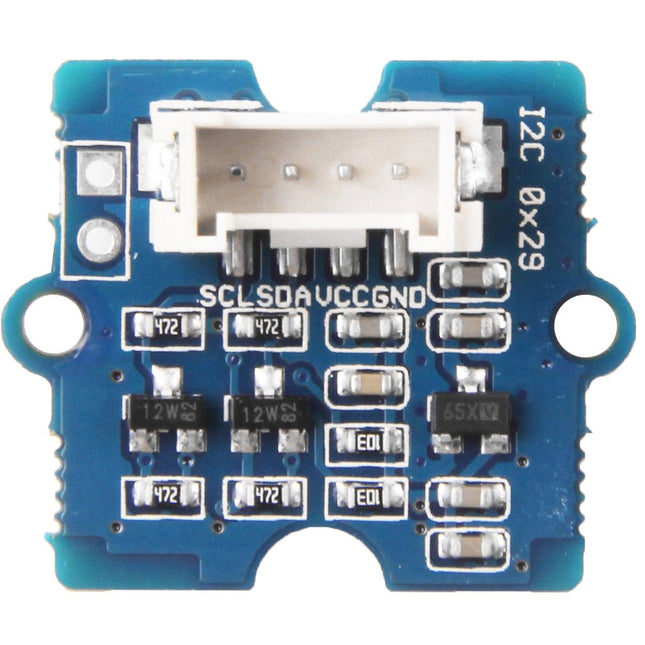
Grove - Time of Flight Distance Sensor-VL53L0X is a high speed, high accuracy and long range distance sensor based on VL53L0X. The VL53L0X is a new generation Time-of-Flight (ToF) laser-ranging module and it is one of the smallest on the market today. It provides accurate distance measurement independent of the target reflectances, making it superior to other conventional technologies. It can measure absolute distances up to 2 m, raising the standards in ranging performance levels and allowing various new applications. The VL53L0X integrates a leading-edge SPAD array (Single Photon Avalanche Diodes) and embeds ST’s second generation Flight SenseTM patented technology. The VL53L0X’s 940 nm VCSEL emitter (Vertical-Cavity Surface-Emitting Laser), is totally invisible to the human eye, coupled with internal physical infrared filters, it enables longer ranging distances, higher immunity to ambient light, and better robustness to cover glass optical crosstalk. Features VCSEL driver Ranging sensor with advanced embedded microcontroller Advanced embedded optical cross-talk compensation to simplify cover glass selection Safe for eyes: Class 1 laser device compliant with latest standard IEC 60825-1:2014 - 3rd edition Single power supply I²C interface for device control and data transfer Xshutdown (reset) and interrupt GPIO Programmable I²C address Working voltage: 3.3 V / 5 V Working temperature: 20 ℃ - 70 ℃ Recommended measurement distance: 30 mm - 1000 mm Default I²C address: 0x52 Included 1x Grove - Time of Flight Distance Sensor-VL53L0X 1x Grove Cable
The starter kit for Jetson Nano is one of the best kits for beginners to get started with Jetson Nano. This kit includes 32 GB MicroSD card, 20 W adapter, 2-pin jumper, camera, and micro-USB cable.
Features
32 GB High-performance MicroSD card
5 V 4 A power supply with 2.1 mm DC barrel connector
2-pin jumper
Raspberry Pi camera module V2
Micro-B To Type-A USB cable with DATA enabled
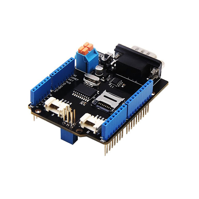
Features Implements CAN V2.0B at up to 1 Mb/s Industrial standard 9 pin sub-D connector OBD-II and CAN standard pinout selectable. Changeable chip select pin Changeable CS pin for TF card slot Changeable INT pin Screw terminal that easily to connect CAN_H and CAN_L Arduino Uno pin headers Micro SD card holder 2 Grove connectors (I2C and UART) SPI Interface up to 10 MHz Standard (11 bit) and extended (29 bit) data and remote frames Two receive buffers with prioritized message storage
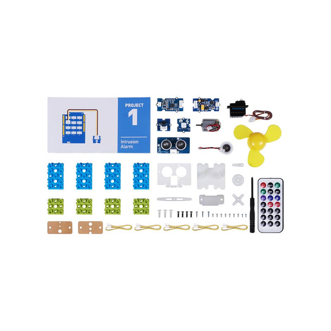
This is an add-on kit for the Seeed Studio Grove Beginner Kit for Arduino.
Applications
Suitable for Arduino beginners
Suitable for infrared control and motion detect
Suitable for getting started with open-source hardware and Arduino coding
Included
1x Grove Water Atomization
1x Grove Mini Fan
1x Grove Servo
1x Grove Ultrasonic Distance Sensor
1x Grove Infrared Receiver
1x Grove Mini PIR Motion Sensor
1x Grove Green Wrapper
1x Grove Blue Wrapper
5x Grove Cable
1x Infrared Remote Control Key
1x Ultrasonic Sensor Bracket Set
1x Motor Bracket Set
1x Servo Base
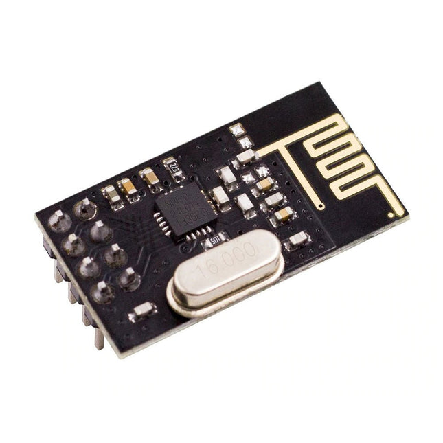
NRF24L01 is a universal ISM band monolithic transceiver chip works in the 2.4-2.5 GHz.
Features
Wireless transceiver including: Frequency generator, enhanced type, SchockBurstTM, mode controller, power amplifier, crystal amplifier, modulator, demodulator
The output power channel selection and protocol settings can be set extremely low current consumption, through the SPI interface
As the transmit mode, the transmit power is 6 dBm, the current is 9.0 mA, the accepted mode current is 12.3 mA, the current consumption of the power-down mode and standby mode are lower
Built-in 2.4 GHz antenna, supports up to six channels of data reception
Size: 15 x 29 mm (including antenna)
The Arduino Pro Portenta Vision Shield LoRa brings industry-rated features to your Portenta. This hardware add-on will let you run embedded computer vision applications, connect wirelessly via LoRa to the Arduino Cloud or your own infrastructure, and activate your system upon the detection of sound events.
The shield comes with:
a 320x320 pixels camera sensor: use one of the cores in Portenta to run image recognition algorithms using the OpenMV for Arduino editor
long range 868/915 MHz LoRa wireless connectivity: get your Portenta H7 connected to the Internet of Things with low power consumption
two on-board microphones for directional sound detection: capture and analyse sound in real-time
JTAG connector: perform low-level debugging of your Portenta board or special firmware updates using an external programmer
SD-Card connector: store your captured data in the card, or read configuration files
The Vision Shield LoRa has been designed to work with the Arduino Portenta H7. The Portenta boards feature multicore 32-bit ARM Cortex processors running at hundreds of megahertz, with megabytes of program memory and RAM. Portenta boards come with WiFi and Bluetooth.
Specifications
Camera
Himax HM-01B0 camera module (manufacturer site)
Resolution
320 x 320 active pixel resolution with support for QVGA
Image sensor
High sensitivity 3.6μ BrightSense pixel technology
Microphone
2x MP34DT05 (datasheet)
Connectivity
868/915MHz ABZ-093 LoRa Module with ARM Cortex-M0+ (datasheet)
Dimensions
66 x 25 mm
Weight
8 g
Downloads
Datasheet
Schematics
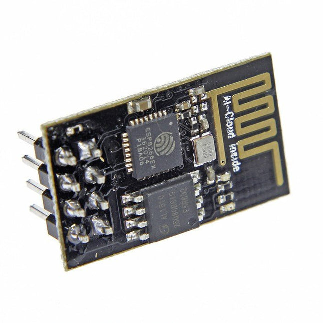
The ESP8266 is an impressive, low cost WiFi module suitable for adding WiFi functionality to an existing microcontroller project via a UART serial connection. The module can even be reprogrammed to act as a standalone WiFi connected device – just add power!
802.11 b/g/n protocol
Wi-Fi Direct (P2P), soft-AP
Integrated TCP/IP protocol stack
This module is a self-contained SOC (System On a Chip) that doesn’t necessarily need a microcontroller to manipulate inputs and outputs as you would normally do with an Arduino, for example, because the ESP-01 acts as a small computer. Thus, you can give a microcontroller internet access like the Wi-Fi shield does to the Arduino, or you can simply program the ESP8266 to not only have access to a Wi-Fi network, but to act as a microcontroller as well, which makes the ESP8266 very versatile.
Functionality, structure and handling of a power module
For readers with first steps in power management the “Abc of Power Modules” contains the basic principles necessary for the selection and use of a power module. The book describes the technical relationships and parameters related to power modules and the basis for calculation and measurement techniques.
Contents
Basics
This chapter describes the need of a DC/DC voltage converter and its basic functionality. Furthermore, various possibilities for realizing a voltage regulator are presented and the essential advantages of a power module are mentioned.
Circuit topologies
Circuit concepts, buck and boost topologies very frequently used with power modules are explained in detail and further circuit topologies are introduced.
Technology, construction and regulation technology
The mechanical construction of a power module is presented, which has a significant influence on EMC and thermal performance. Furthermore, control methods are explained and circuit design tips are provided in this chapter.
Measuring methods
Meaningful measurement results are absolutely necessary to assess a power module. The relevant measurement points and measurement methods are described in this chapter.
Handling
The aspects of storage and handling of power modules are explained, as well as their manufacturing and soldering processes.
Selection of a power modules
Important parameters and criteria for the optimal selection of a power module are presented in this section.