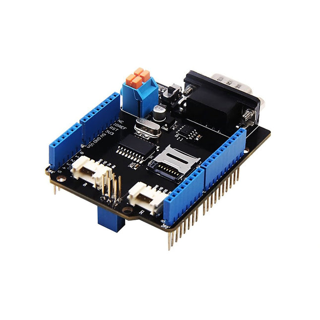
Features Implements CAN V2.0B at up to 1 Mb/s Industrial standard 9 pin sub-D connector OBD-II and CAN standard pinout selectable. Changeable chip select pin Changeable CS pin for TF card slot Changeable INT pin Screw terminal that easily to connect CAN_H and CAN_L Arduino Uno pin headers Micro SD card holder 2 Grove connectors (I2C and UART) SPI Interface up to 10 MHz Standard (11 bit) and extended (29 bit) data and remote frames Two receive buffers with prioritized message storage
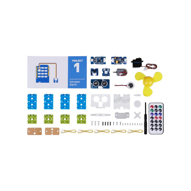
This is an add-on kit for the Seeed Studio Grove Beginner Kit for Arduino.
Applications
Suitable for Arduino beginners
Suitable for infrared control and motion detect
Suitable for getting started with open-source hardware and Arduino coding
Included
1x Grove Water Atomization
1x Grove Mini Fan
1x Grove Servo
1x Grove Ultrasonic Distance Sensor
1x Grove Infrared Receiver
1x Grove Mini PIR Motion Sensor
1x Grove Green Wrapper
1x Grove Blue Wrapper
5x Grove Cable
1x Infrared Remote Control Key
1x Ultrasonic Sensor Bracket Set
1x Motor Bracket Set
1x Servo Base
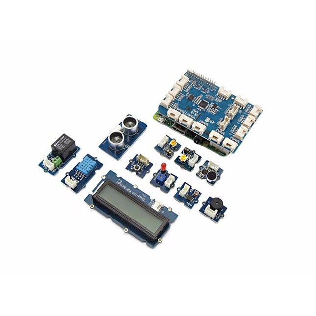
GrovePi+ is stacked on top of the Raspberry Pi without the need for any other connections. Communication between the two occurs over the I²C interface. All Grove modules connect to the universal Grove connectors on the GrovePi+ shield via the universal 4-pin connector cable.
Grove modules work on analog and digital signals and can be connected directly to the ATMEGA328 microcontroller on the Grove Pi+. The microcontroller acts as an interpreter between the Raspberry Pi and the Grove sensors. It sends, receives, and executes commands sent by the Raspberry Pi.
Features
One GrovePi+ board together with 12 popular Grove sensors and 10 Grove cables
GrovePi+ is compatible with Raspberry Pi A+, B, B+ / 2, 3, 4.
CE certified and compatible with Linux and Win 10 IoT.
Included
1x Grove Pi+
1x Grove - Rotary Angle Sensor
1x Grove - Sound Sensor
1x Grove - LCD RGB Backlight
1x Grove - Temp&Humi Sensor
1x Grove - Red LED
1x Grove - Light Sensor
1x Grove - Buzzer
1x Grove - Relay
1x Grove - Blue LED
1x Grove - Button
1x GrovePi+ Guidebook
10x Cables
1x Grove - UItrasonic Ranger
1x Grove - Green LED
The starter kit for Jetson Nano is one of the best kits for beginners to get started with Jetson Nano. This kit includes 32 GB MicroSD card, 20 W adapter, 2-pin jumper, camera, and micro-USB cable.
Features
32 GB High-performance MicroSD card
5 V 4 A power supply with 2.1 mm DC barrel connector
2-pin jumper
Raspberry Pi camera module V2
Micro-B To Type-A USB cable with DATA enabled
The GrovePi+ is an easy-to-use and modular system for hardware hacking with the Raspberry Pi, no need for soldering or breadboards: plug in your Grove sensors and start programming directly.
Grove is an easy-to-use collection of more than 100 inexpensive plug-and-play modules that sense and control the physical world. By connecting Grove Sensors to Raspberry Pi, it empowers your Pi in the physical world. With hundreds of sensors to choose from Grove families, the possibilities for interaction are endless.
Set-up in 4 simple steps
Slip the GrovePi+ board over your Raspberry Pi
Connect the Grove modules to the GrovePi+ board
Upload your program to Raspberry Pi
Begin taking in the world data
Features Integrated Cold-Junction Compensation Supported Types (designated by NIST ITS-90): Type K, J, T, N, S, E, B and R Four Programmable Temperature Alert Outputs: Monitor Hot- or Cold-Junction Temperatures Detect rising or falling temperatures Up to 255°C of Programmable Hysteresis Programmable Digital Filter for Temperature Low Power Dimensions: 20 mm x 40 mm x 18 mm Weight: 18 g Application Petrochemical Thermal Management Hand-Held Measurement Equipment Industrial Equipment Thermal Management Ovens Industrial Engine Thermal Monitor Temperature Detection Racks Downloads Eagle Files Github library Datasheet
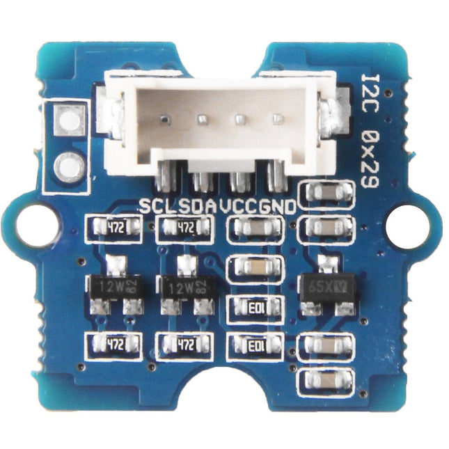
Grove - Time of Flight Distance Sensor-VL53L0X is a high speed, high accuracy and long range distance sensor based on VL53L0X. The VL53L0X is a new generation Time-of-Flight (ToF) laser-ranging module and it is one of the smallest on the market today. It provides accurate distance measurement independent of the target reflectances, making it superior to other conventional technologies. It can measure absolute distances up to 2 m, raising the standards in ranging performance levels and allowing various new applications. The VL53L0X integrates a leading-edge SPAD array (Single Photon Avalanche Diodes) and embeds ST’s second generation Flight SenseTM patented technology. The VL53L0X’s 940 nm VCSEL emitter (Vertical-Cavity Surface-Emitting Laser), is totally invisible to the human eye, coupled with internal physical infrared filters, it enables longer ranging distances, higher immunity to ambient light, and better robustness to cover glass optical crosstalk. Features VCSEL driver Ranging sensor with advanced embedded microcontroller Advanced embedded optical cross-talk compensation to simplify cover glass selection Safe for eyes: Class 1 laser device compliant with latest standard IEC 60825-1:2014 - 3rd edition Single power supply I²C interface for device control and data transfer Xshutdown (reset) and interrupt GPIO Programmable I²C address Working voltage: 3.3 V / 5 V Working temperature: 20 ℃ - 70 ℃ Recommended measurement distance: 30 mm - 1000 mm Default I²C address: 0x52 Included 1x Grove - Time of Flight Distance Sensor-VL53L0X 1x Grove Cable
This book details the use of the Arduino Uno and the Raspberry Pi 4 in practical CAN bus based projects. Using either the Arduino Uno or the Raspberry Pi with off-the-shelf CAN bus interface modules considerably ease developing, debugging, and testing CAN bus based projects.
This book is written for students, practicing engineers, enthusiasts, and for everyone else wanting to learn more about the CAN bus and its applications. The book assumes that the reader has some knowledge of basic electronics. Knowledge of the C and Python programming languages and programming the Arduino Uno using its IDE and Raspberry Pi will be useful, especially if the reader intends to develop microcontroller-based projects using the CAN bus.
The book should be a useful source of reference material for anyone interested in finding answers to questions such as:
What bus systems are available for the automotive industry?
What are the principles of the CAN bus?
How can I create a physical CAN bus?
What types of frames (or data packets) are available in a CAN bus system?
How can errors be detected in a CAN bus system and how dependable is a CAN bus system?
What types of CAN bus controllers exist?
How do I use the MCP2515 CAN bus controller?
How do I create 2-node Arduino Uno-based CAN bus projects?
How do I create 3-node Arduino Uno-based CAN bus projects?
How do I set the acceptance masks and acceptance filters?
How do I analyze data on the CAN bus?
How do I create 2-node Raspberry Pi-based CAN bus projects?
How do I create 3-node Raspberry Pi-based CAN bus projects?
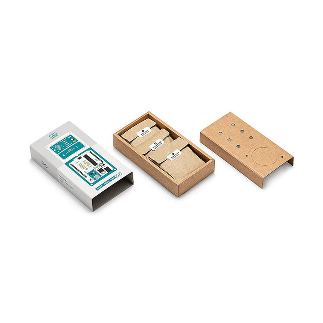
Learn the basics of electronics by assembling manually your Arduino Uno, become familiar with soldering by mounting every single component, and then unleash your creativity with the only kit that becomes a synth!
The Arduino Make-Your-Uno kit is really the best way to learn how to solder. And when you are done, the packaging allows you to build a synth and make your music.
A kit with all the components to build your very own Arduino Uno and audio synthesizer shield.
The Make-Your-Uno kit comes with a complete set of instructions in a dedicated content platform. This includes video material, a 3D interactive viewer for following detailed instructions, and how to program your board once it is finished.
This kit contains:
Arduino Make-Your-Uno
1x Make-Your-Uno PCB
1x USB C Serial adapter Board
7x Resistors 1k Ohm
2x Resistors 10k Ohm
2x Resistors 1M Ohm
1x Diode (1N4007)
1x 16 MHz Crystal
4x Yellow LEDs
1x Green LED
1x Push-Button
1x MOSFET
1x LDO (3.3 V)
1x LDO (5 V)
3x Ceramic capacitors (22pF)
3x Electrolytic capacitors (47uF)
7x Polyester capacitors (100nF)
1x Socket for ATMega 328p
2x I/O Connectors
1x Connector header 6 pins
1x Barrel jack connector
1x ATmega 328p Microcontroller
Arduino Audio Synth
1x Audio Synth PCB
1x Resistor 100k Ohm
1x Resistor 10 Ohm
1x Audio amplifier (LM386)
1x Ceramic capacitors (47nF)
1x Electrolytic capacitors (47uF)
1x Electrolytic capacitors (220uF)
1x Polyester capacitor (100nF)
4x connectors pin header
6x potentiometer 10k Ohm with plastic knobs
Spare parts
2x Electrolytic capacitors (47uF)
2x Polyester capacitor (100nF)
2x Ceramic capacitors (22pF)
1x Push-Button
1x Yellow LEDs
1x Green LED
Mechanical parts
5x Spacers 12 mm
11x Spacers 6 mm
5x screw nuts
2x screws 12 mm
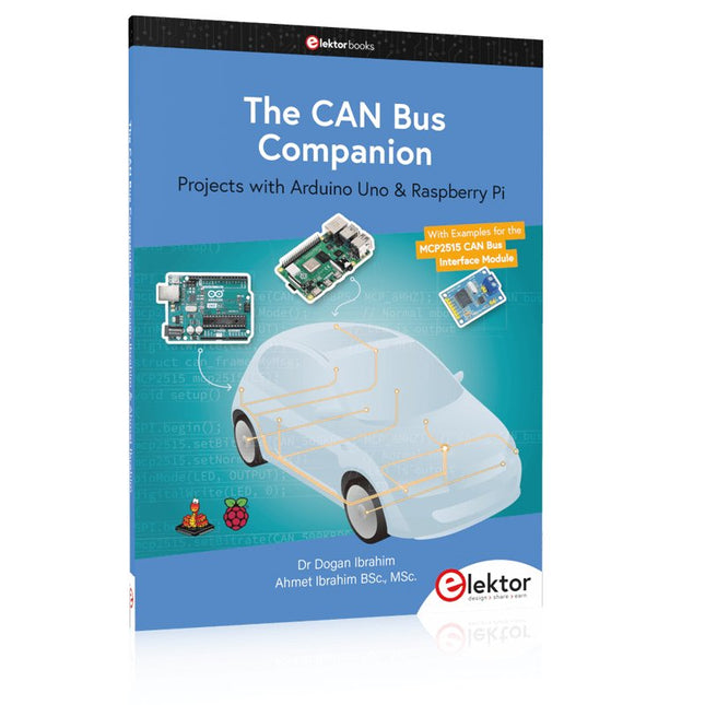
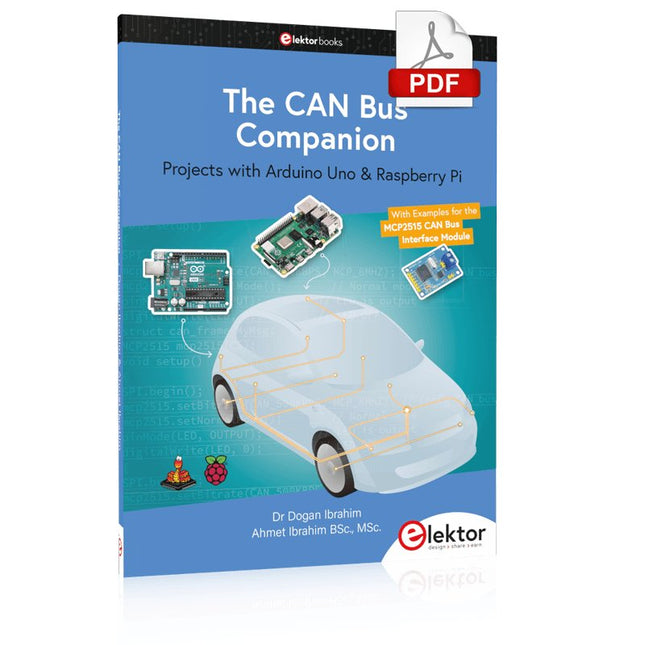
Projects with Arduino Uno & Raspberry Pi with Examples for the MCP2515 CAN Bus Interface Module
This book details the use of the Arduino Uno and the Raspberry Pi 4 in practical CAN bus based projects. Using either the Arduino Uno or the Raspberry Pi with off-the-shelf CAN bus interface modules considerably ease developing, debugging, and testing CAN bus based projects.
This book is written for students, practicing engineers, enthusiasts, and for everyone else wanting to learn more about the CAN bus and its applications. The book assumes that the reader has some knowledge of basic electronics. Knowledge of the C and Python programming languages and programming the Arduino Uno using its IDE and Raspberry Pi will be useful, especially if the reader intends to develop microcontroller-based projects using the CAN bus.
The book should be a useful source of reference material for anyone interested in finding answers to questions such as:
What bus systems are available for the automotive industry?
What are the principles of the CAN bus?
How can I create a physical CAN bus?
What types of frames (or data packets) are available in a CAN bus system?
How can errors be detected in a CAN bus system and how dependable is a CAN bus system?
What types of CAN bus controllers exist?
How do I use the MCP2515 CAN bus controller?
How do I create 2-node Arduino Uno-based CAN bus projects?
How do I create 3-node Arduino Uno-based CAN bus projects?
How do I set the acceptance masks and acceptance filters?
How do I analyze data on the CAN bus?
How do I create 2-node Raspberry Pi-based CAN bus projects?
How do I create 3-node Raspberry Pi-based CAN bus projects?
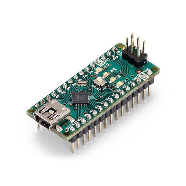
The Arduino Nano is a small, complete, and breadboard-friendly board based on the ATmega328 (Arduino Nano 3.x). It has more or less the same functionality of the Arduino Duemilanove but in a different package. It lacks only a DC power jack and works with a Mini-B USB cable instead of a standard one.
Specifications
Microcontroller
ATmega328
Operating Voltage (logic level)
5 V
Input Voltage (recommended)
7-12 V
Input Voltage (limits)
6-20 V
Digital I/O Pins
14 (of which 6 provide PWM output)
Analog Input Pins
8
DC Current per I/O Pin
40 mA
Flash Memory
16 KB (ATmega168) or 32 KB (ATmega328) of which 2 KB used by bootloader
SRAM
1 KB (ATmega168) or 2 KB (ATmega328)
EEPROM
512 bytes (ATmega168) or 1 KB (ATmega328)
Clock Speed
16 MHz
Dimensions
0.73 x 1.70' (18 x 45 mm)
Power
The Arduino Nano can be powered via the Mini-B USB connection, 6-20 V unregulated external power supply (pin 30), or 5 V regulated external power supply (pin 27). The power source is automatically selected to the highest voltage source.
Memory
The ATmega168 has 16 KB of flash memory for storing code (of which 2 KB is used for the bootloader), 1 KB of SRAM and 512 bytes of EEPROM
The ATmega328 has 32 KB of flash memory for storing code, (also with 2 KB used for the bootloader), 2 KB of SRAM and 1 KB of EEPROM.
Input and Output
Each of the 14 digital pins on the Nano can be used as an input or output, using pinMode(), digitalWrite(), and digitalRead() functions. They operate at 5 V.
Each pin can provide or receive a maximum of 40 mA and has an internal pull-up resistor (disconnected by default) of 20-50 kOhms.
Communication
The Arduino Nano has a number of facilities for communicating with a computer, another Arduino, or other microcontrollers.
The ATmega168 and ATmega328 provide UART TTL (5V) serial communication, which is available on digital pins 0 (RX) and 1 (TX). An FTDI FT232RL on the board channels this serial communication over USB and the FTDI drivers (included with the Arduino software) provide a virtual com port to software on the computer.
The Arduino software includes a serial monitor which allows simple textual data to be sent to and from the Arduino board. The RX and TX LEDs on the board will flash when data is being transmitted via the FTDI chip and USB connection to the computer (but not for serial communication on pins 0 and 1).
A SoftwareSerial library allows for serial communication on any of the Nano's digital pins.
Programming
The Arduino Nano can be programmed with the Arduino software (download).
The ATmega168 or ATmega328 on the Arduino Nano comes with a bootloader that allows you to upload new code to it without the use of an external hardware programmer. It communicates using the original STK500 protocol (reference, C header files).
You can also bypass the bootloader and program the microcontroller through the ICSP (In-Circuit Serial Programming) header using Arduino ISP or similar; see these instructions for details.
Automatic (Software) Reset
Rather than requiring a physical press of the reset button before an upload, the Arduino Nano is designed in a way that allows it to be reset by software running on a connected computer.
One of the hardware flow control lines (DTR) of theFT232RL is connected to the reset line of the ATmega168 or ATmega328 via a 100 nF capacitor. When this line is asserted (taken low), the reset line drops long enough to reset the chip.
The Arduino software uses this capability to allow you to upload code by simply pressing the upload button in the Arduino environment. This means that the bootloader can have a shorter timeout, as the lowering of DTR can be well-coordinated with the start of the upload.
The Elektor MultiCalculator Kit is an Arduino-based multifunction calculator that goes beyond basic calculations. It offers 22 functions including light and temperature measurement, differential temperature analysis, and NEC IR remote control decoding. The Elektor MultiCalculator is a handy tool for use in your projects or for educational purposes.
The kit features a Pro Mini module as the computing unit. The PCB is easy to assemble using through-hole components. The enclosure consists of 11 acrylic panels and mounting materials for easy assembly. Additionally, the device is equipped with a 16x2 alphanumeric LCD, 20 buttons, and temperature sensors.
The Elektor MultiCalculator is programmable with the Arduino IDE through a 6-way PCB header. The available software is bilingual (English and Dutch). The calculator can be programmed with a programming adapter, and it is powered through USB-C.
Modes of Operation
Calculator
4-Ring Resistor Code
5-Ring Resistor Code
Decimal to Hexadecimal and Character (ASCII) conversion
Hexadecimal to Decimal and Character (ASCII) conversion
Decimal to Binary and Character (ASCII) conversion
Binary to Decimal and Hexadecimal conversion
Hz, nF, capacitive reactance (XC) calculation
Hz, µH, inductive reactance (XL) calculation
Resistance calculation of two resistors connected in parallel
Resistance calculation of two resistors connected in series
Calculation of unknown parallel resistor
Temperature measurement
Differential temperature measurement T1&T2 and Delta (δ)
Light measurement
Stopwatch with lap time function
Item counter
NEC IR remote control decoding
AWG conversion (American Wire Gauge)
Rolling Dice
Personalize startup message
Temperature calibration
Specifications
Menu languages: English, Dutch
Dimensions: 92 x 138 x 40 mm
Build time: approx. 5 hours
Included
PCB and though-hole components
Precut acrylic sheets with all mechanical parts
Pro Mini microcontroller module (ATmega328/5 V/16 MHz)
Programming adapter
Waterproof temperature sensors
USB-C cable
Downloads
Software