Search results for "robotik OR und OR kunstliche OR intelligenz"
-
Elektor Digital Elektor Special: Power Supplies and Batteries (PDF)
Whatever the methods or even then financial means you have to make your circuits work, the power supply should rank high if not Number One in your considerations. The design block simply called “power supply” is hugely underrated both in electronics creation and repair. Yet, the “PSU” has enormous diversity and comes in wildly differing guises like AC/DC, generator, battery (rechargeable or not), PV panel, benchtop, linear or switch-mode, to mention but a few. The output ranges are also staggering like nano-amps to kiloamps and the same for voltages.This special covers the features and design aspects of power supplies.ContentsBasics Battery ManagementWhat to be aware of when using (Lithium) batteries. Fixed-Voltage Power Supply using Linear RegulatorsThe best result right after batteries. Light Energy HarvestingA small solar panel is used in an energy harvesting project to manage and charge four AAA cells. Mains Powered Adapter DesignBasic circuits and tips for transformers, rectification, filtering and stabilization. LM317 Soft StartThe high inrush current pulse should be avoided. Controllable RectifiersSome suggestions to keep the power loss in the linear regulator as low as possible. Components Worksheet: The LM117 / LM217 / LM317 Voltage Regulators SupercapsLow voltage but lots of current… or not? Reviews JOY-iT RD6006 Benchtop Power Supply Kit Siglent SDL1020X Programmable DC Electronic Load Projects Balcony Power PlantDIY solar balcony = speedy payback! DIY LiPo Supercharger KitFrom handcrafted to mass market Dual-Anode MOSFET ThyristorFaster and less wasteful than the old SCR Battery JuicerDo not throw away, squeeze! High-Voltage Power Supply with Curve TracerGenerate voltages up to 400 V and trace characteristics curves for valves and transistors High Voltage Supply for RIAAFor RIAA tube preamps and other applications. MicroSupplyA lab power supply for connected devices Phantom Power Supply using Switched CapacitorsVoltage tripler using three ICs The SMPS800RE Switch-Mode Supply for the Elektor Fortissimo-100Reliable, light and affordable Soft Start for PSUBe nice to your power supply – and its load UniLab 20-30 V, 3 A compact switch-mode lab power supply Tips Soft Start for Step-Down Switching Regulators Low Loss Current Limit Powerbank Surprise A Virtual Ground Battery Maintainer Battery Pack Discharger Connecting Voltage Regulators in Parallel
€ 11,95
Members € 10,76
-

SparkFun SparkFun MicroMod Input and Display Carrier Board
This carrier board combines a 2.4" TFT display, six addressable LEDs, onboard voltage regulator, a 6-pin IO connector, and microSD slot with the M.2 pin connector slot so that it can be used with compatible processor boards in our MicroMod ecosystem. We've also populated this carrier board with Atmel's ATtiny84 with 8kb of programmable flash. This little guy is pre-programmed to communicate with the processor over I²C to read button presses. Features M.2 MicroMod Connector 240 x 320 pixel, 2.4" TFT display 6 Addressable APA102 LEDs Magnetic Buzzer USB-C Connector 3.3 V 1 A Voltage Regulator Qwiic Connector Boot/Reset Buttons RTC Backup Battery & Charge Circuit microSD Phillips #0 M2.5 x 3 mm screw included
€ 72,95€ 29,18
Members identical
-
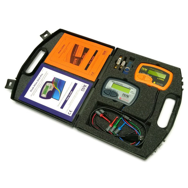
Peak Peak Atlas Pro Pack (LCR45 & DCA75)
This pack contains the LCR45 Passive Component Impedance Meter, great for advanced hobbyists and professionals. It also contains the very popular DCA Pro (model DCA75), fantastic for component identification, pinout identification, detailed characteristic measurement and curve tracing on a PC. Complete with USB cable and software on a USB flash drive. DCA75 Building on the continued success of Peak's existing component identification and analysis instruments, the DCA Pro brings an array of exciting new features for the hobbyist and professional alike. The DCA Pro is an advanced new design that features a graphics display, USB communications, PC Software and an enhanced component identification library. Automatic component type identification Automatic pinout identification (connect any way round) The DCA Pro supports all the components that the popular Peak Atlas DCA55 supports, but adds plenty more. Components supported include: Transistors (including Darlingtons), Silicon and Germanium types. Measures gain, Vbe and leakage MOSFETs, enhancement mode and depletion mode types. Measure on-threshold (at 5 mA) and approx transconductance (for span of 3-5 mA) JFETs, including normally off SiC types. Measures pinch-off voltage (at 1 uA) and approx transconductance (for span of 3-5 mA) IGBTs (insulated gate bipolar transistors). Measures on-threshold (at 5 mA) Diodes and Diode networks LEDs and bicolour LEDs (2 lead and 3 lead types) Zener Diodes with measurement of zener voltage up to 9 V at 5 mA Voltage regulators (measures regulation voltage, drop-out voltage, quiescent current) Triacs and Thyristors that require less than 10 mA of gate current and holding current Stand-alone or with a PC The instrument can be used stand-alone or connected to a PC. Either way, the DCA Pro will automatically identify the component type, identify the pinout and also measure a range of component parameters such as transistor gain, leakage, MOSFET and IGBT threshold voltages, pn characteristics and much more. Curve Tracing When connected to a PC using the supplied USB cable, a range of low current curve-tracing functions can be performed. Various graph types are available, with more to follow: Bipolar transistor output characteristics, IC vs VCE Bipolar transistor gain characteristics, HFE vs VCE Bipolar transistor gain characteristics, HFE vs IC MOSFET and IGBT output function, ID vs VDS MOSFET and IGBT transfer function, ID vs VGS JFET output function, ID vs VDS JFET transfer function, ID vs VGS Voltage regulator, VOUT vs VIN Voltage regulator, IQ vs VIN. PN junction I/V curves, forward and reverse options (for Zener diodes) Curve tracing is performed using test parameters in the range of +/-12 V or +/-12 mA. All curve-tracing data can be instantly pasted into Excel for further graphing and analysis. PC Software is included with the DCA Pro on a Peak USB memory stick. Software designed for Windows 7 and higher (all 32 or 64 bit). LCR45 A great handheld LCR analyzer that can measure the value of your passive component (inductor, capacitor or resistor) and also measure the detailed impedance in a number of modes. The LCR45 offers enhanced measurement resolution (better than 0.1 uH!) whilst also giving you continuous fluid measurements. Additionally, the test frequencies of DC, 1 kHz, 15 kHz and 200 kHz can be set to automatic or manual modes. Supplied with removable gold plated hook probes, battery and user guide. Compatible with standard 2 mm test connectors. Not designed for in-circuit use. Automatic or manual component type selection: Inductor, Capacitor or Resistor Automatic or manual test frequency selection: DC, 1 kHz, 15 kHz and 200 kHz Inductance from 0.1 uH to 10 H Capacitance from 0.1 pF to 10,000 uF Resistance from 0.1 Ohm to 2 MOhm Inductance measurement also shows DC winding resistance Display of "Component type and values", "Complex Impedance", "Magnitude/Phase" and "Admittance" Test frequency displayed for all measurements Typical accuracy of 1.5% for inductors and capacitors (see spec table for details) Typical accuracy of 1% for resistors Test lead complete with gold plated 2 mm plugs and sockets Supplied with removable gold plated hook probes Included LCR45 DCA75 Extra GP23 Battery Extra AAA cell Dual Carry Case
€ 270,00
-
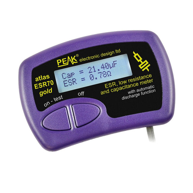
Peak Peak Atlas ESR70 gold (ESR and Capacitance Meter)
The Peak Atlas ESR70 gold is an enhanced version of the previous Peak Atlas ESR70 Plus. It does everything that the ESR70 Plus did but better. It now measures capacitance up to 10x faster, and over a wider range, thanks to new test algorithms. The capacitance measurement is also much less influenced by parallel resistances or leakage current thanks to our new Triple-Slope measurement system. Using the supplied gold plated probes (removable), the Atlas ESR70 gold can measure ESR down to a resolution of 0.01 ohms, up to 40 ohms. It can even measure ESR for capacitors that are in-circuit. Probes are removable, allowing 2 mm compatible probes to be fitted. Audible alerts are produced for various ESR levels allowing you to perform many tests in succession without having to look at the display. The ESR70 automatically takes capacitive reactance into account, so even low value capacitors (down to 0.3 uF) can have the ESR measured accurately. Features Uses a single AAA Alkaline cell (included) Alphanumeric LCD with backlight Automatic analysis-start when you apply the probes Automatic capacitor discharge using controlled discharge function ESR (and low DC resistance) measurement (even in-circuit) Capacitive reactance automatically taken into account to ensure accurate ESR Capacitance measurement (if testing out-of-circuit) Audible alerts for various ESR levels Extended ESR measurement range up to 40 Ohms Optional probe alternatives easily fitted New gold Features Improved LCD with better backlight 10x faster capacitance measurement for large capacitors Enhanced user options system New triple-slope measurement system to vastly reduce the influence of parallel resistance and/or leakage current on capacitance measurements Much wider capacitance measurement range now 0.3 uF to 90,000 uF (was 1uF to 22,000uF) Specifications Analyzer type ESR and Capacitance Component types Capacitors (>0.3 uF) ESR range 0.00 Ohms to 40.0 Ohms ESR resolution From 0.01 Ohms In-circuit use ESR only Capacitance range 0.3 uF to 90000 uF Battery type 1.5 V Alkaline AAA Cell (supplied). Life typically 1500 ops Display type Alphanumeric LCD (with backlight) Included Peak Atlas ESR70 gold Extra-long and extra-flexible test cables (450 mm of Silicone covered cable) 2 mm gold plated plugs and sockets with removeable gold plated crocodile clips Comprehensive illustrated user guide AAA Alkaline cell Downloads Datasheet (EN) User Guide (EN) User Guide (FR) User Guide (IT)
€ 99,00
-

FNIRSI FNIRSI HRM-10 Battery Internal Resistance & Voltage Tester
The FNIRSI HRM-10 is a portable, high-precision battery internal resistance and voltage tester. This device offers true four-wire measurement and is designed for both accuracy and ease of use. It automatically measures internal resistance and voltage values simultaneously, displaying the results on its HD color screen. Users have the option to manually adjust voltage and resistance ranges to suit their needs. The device also includes a sorting mode that automatically filters the good and bad batteries based on user-set thresholds. Additionally, it supports the storage of historical data and allows for exporting measurement records in table format. Features High Measurement Accuracy Tabular Data Export Auto-Evaluate Measurement Results 8 Threshold Settings HD Color Screen Folding Stand 1000 mAh Lithium Battery Specifications Voltage Resistance Measuring range 0-100 V (DC) 0-200 Ω Accuracy ±0.5% ±0.5% Gear Automatic, 1 V, 10 V, 100 V Automatic, 20 mΩ, 200 mΩ, 2 Ω, 20 Ω, 200 Ω Instrument test signal frequency 1 Khz (AC) Rechargeable USB-C (5 V/1 A) Built-in battery 1000 mAh lithium battery User calibration Yes Sorting mode Yes History record Yes Recorded data export Yes Working environment –10°C to +45°C, relative humidity <80% Storage environment –20°C to +80°C, relative humidity <80% Dimensions 158.7 x 80.5 x 28.4 mm Weight 225 g Included 1x FNIRSI HRM-10 Internal Resistance Tester 1x Clip Test Line 1x USB-C data cable 1x Manual Downloads Manual Firmware V0.3
€ 49,95
-

Elektor Digital Explore ATtiny Microcontrollers using C and Assembly Language (E-book)
AVR Architecture and Programming An in-depth look at the 8-bit AVR architecture found in ATtiny and ATmega microcontrollers, mainly from a software and programming point of view. Explore the AVR architecture using C and assembly language in Microchip Studio (formerly Atmel Studio) with ATtiny microcontrollers. Learn the details of how AVR microcontrollers work internally, including the internal registers and memory map of ATtiny devices. Program ATtiny microcontrollers using an Atmel-ICE programmer/debugger, or use a cheap hobby programmer, or even an Arduino Uno as a programmer. Most code examples can be run using the Microchip Studio AVR simulator. Learn to write programs for ATtiny microcontrollers in assembly language. See how assembly language is converted to machine code instructions by the assembler program. Find out how programs written in the C programming language end up as assembly language and finally as machine code instructions. Use the Microchip Studio debugger in combination with a hardware USB programmer/debugger to test assembly and C language programs, or use the Microchip Studio AVR simulator. DIP packaged ATtiny microcontrollers are used in this volume for easy use on electronic breadboards, targeting mainly the ATtiny13(A) and ATtiny25/45/85. Learn about instruction timing and clocks in AVR microcontrollers using ATtiny devices. Be on your way to becoming an AVR expert with advanced debugging and programming skills.
€ 34,95
Members € 27,96
-
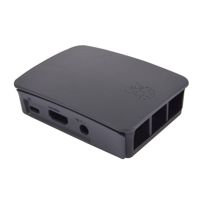
Raspberry Pi Foundation Official Case for Raspberry Pi 3, 2 and B+ (black/grey)
High-quality ABS construction Removable side panels and lid for easy access to GPIO, camera and display connectors Light pipes for power and activity LEDs Extraordinarily handsome Colour: black/grey
€ 7,95€ 3,18
Members identical
-
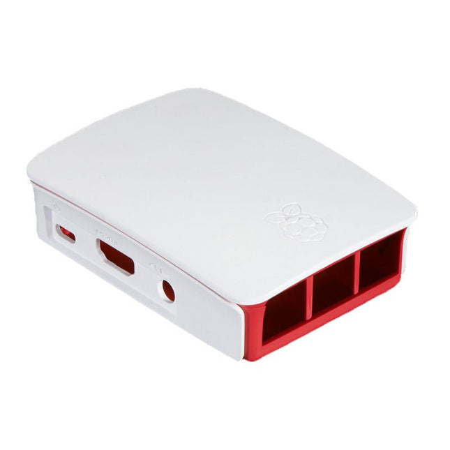
Raspberry Pi Foundation Official Case for Raspberry Pi 3, 2 and B+ (white/red)
High-quality ABS construction Removable side panels and lid for easy access to GPIO, camera and display connectors Light pipes for power and activity LEDs Extraordinarily handsome Colour: white/red
€ 7,95€ 3,18
Members identical
-
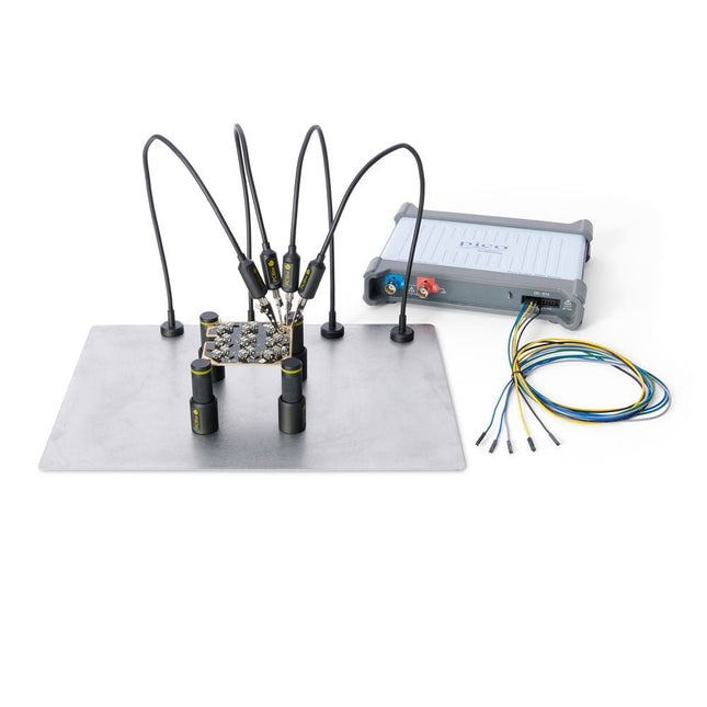
Sensepeek Sensepeek 4003 PCBite Kit incl. 4x SP10 Probe and Test Wires
The minimalist design and the spring loaded test needle makes it possible to simultaneously measure on fine pitch components and nearby signals. The probe is steady but yet flexible made for instant measurements or total hands-free operations together with your multimeter, logic analyzer or preferred tool. The dual pin header connector fits directly on a 2.54 mm (0.100”) connector. The SP10 comes with a powerful magnet in the base, as for all PCBite probes and holders which makes the probe easy to place and reposition. Included 4x PCBite holder 1x Large base plate (A4) 4x PCBite probe with pin tipped test needle 4x Extra crown tipped test needle 1x Set of yellow insulation washers 5x Dupont to dupont test wire 2x Banana to dupont test wire 1x Microfiber cloth Downloads User Guide
€ 152,46
-
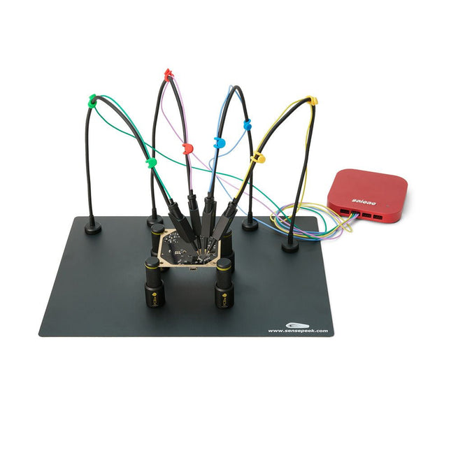
Sensepeek Sensepeek 6003 PCBite Kit incl. 4x SQ10 Probe and Test Wires
The SQ series of handsfree PCBite probes from Sensepeek are insulated, come with included color-coded cable holders and have a lower point of gravity making them even more stable compared with the original SP series of probes. All the loved features of handsfree measurement, exchangeable fine pitch spring tipped test needle and the minimalistic design is maintained to make traditional sized and handheld probes obsolete. Features All handsfree probes from Sensepeek makes instant measurements or long triggering sessions a breeze. No more soldering wires to connect your probe or complicated tools to setup, just positioning the probe needle on any test point or component in the signal path and release. Saves time and frustration during development, verification and repairs. The minimalist design and the spring-loaded test needle makes it possible to simultaneously measure on fine pitch components and nearby signals. Both length and weight of the SQ probes are perfectly balanced to be used with the included PCB holders and base plate which is a must for handsfree function. The probe holder comes with a powerful magnet in the base, as for all PCBite probes and holders which makes the probe easy to place and reposition. The SQ series of probes can be used handheld without the probe holder as they have an insulated grip but their full potential is used when measuring handsfree. One side of the included baseplate is matte and the other is mirror polished. The mirror polished surface makes it easy to see components on the circuit board underside. For added protection during measurement the included insulation cover can be mounted on one of the surfaces. Included 4x PCBite PCB holders 1x Set of yellow insulation washers for the PCB holders 1x Large Base plate (A4) 1x Insulation cover for the base plate (A4) 1x Micro fiber cloth 4x SQ10 probes and pin tipped test needles (black) 2x Banana to dupont test wires (red/black) 5x Dupont to dupont test wires 1x Set of cable holders (4 colors) 4x Extra test needles Downloads User guide (PCBite kit) User guide (SQ10 probes)
€ 180,29


-

, by Clemens Valens The Anet 4540 Desktop CNC and Engraving Machine
Like 3D printers and laser engraving machines, CNC machines have become more mainstream too. Where they used to cost thousands of euros in the past,...
-
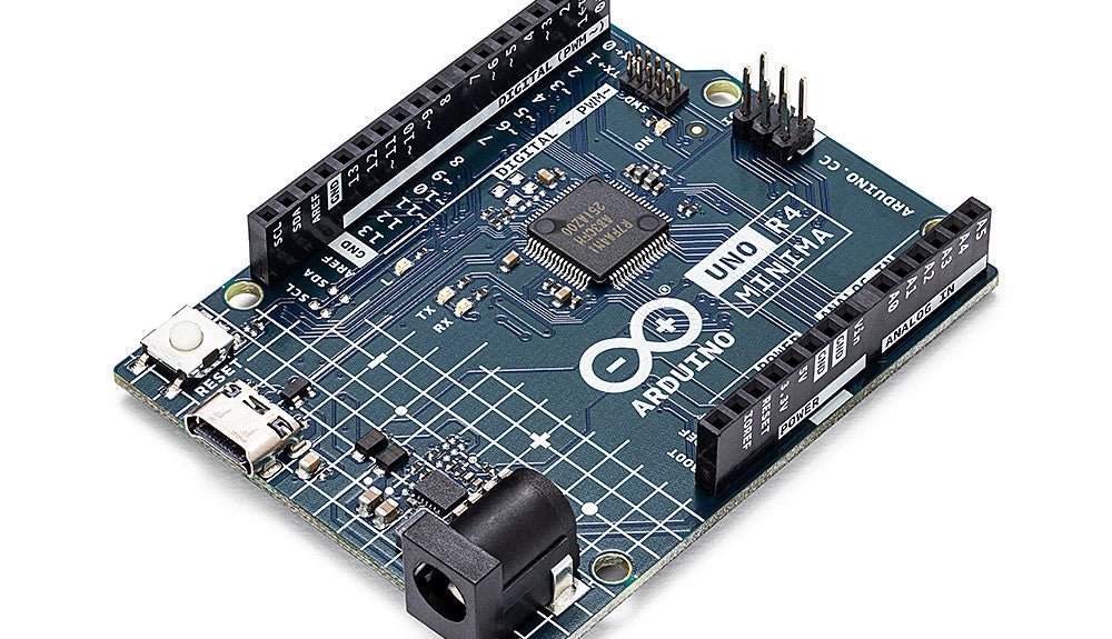
, by Clemens Valens Two New Arduino UNO R4 Boards: Minima and WiFi
The Arduino UNO R4 Minima and the Arduino UNO R4 WiFi have finally hit the shelves, introducing an exciting new chapter for Arduino enthusiasts and...

