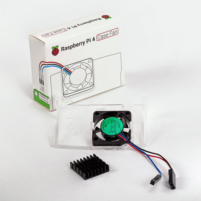
Designed for overclockers and other power users, this fan keeps your Raspberry Pi 4 at a comfortable operating temperature even under heavy load. The temperature-controlled fan delivers up to 1.4 CFM of airflow over the processor, memory, and power management IC. The bundled heatsink (18 x 8 x 10 mm) with self-adhesive pad improves heat transfer from the processor. The Raspberry Pi 4 Case Fan works with Raspberry Pi 4 and the official Raspberry Pi 4 case.
Raspberry Pi DAC+ (formerly known as IQaudio DAC+) is a high-performance audio HAT designed for any Raspberry Pi with a 40-pin GPIO header. Equipped with the Texas Instruments PCM5122 DAC, it delivers crystal-clear stereo analogue audio through a pair of phono (RCA) connectors.
No external power is needed – the DAC+ connects directly to the Raspberry Pi’s GPIO header without requiring soldering or cables.
Features
Power LED
Analogue audio out (0-2 V RMS) via panel-mounted stereo
phono (RCA) sockets with MUTE signal (headphone detect)
Dedicated headphone amplifier, output via 3.5 mm panel-mounted barrel socket
40-pin pass-through GPIO header
HAT EEPROM write-enabled
Downloads
Datasheet
Specifications
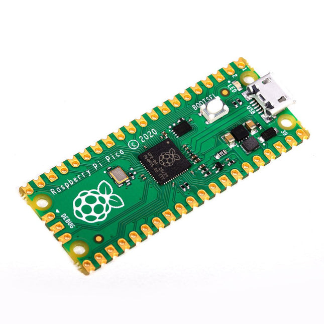
RP2040 microcontroller chip designed by Raspberry Pi in the UK
Dual-core ARM Cortex M0+ processor, with a flexible clock running up to 133 MHz
264 kB SRAM, and 2 MB on-board Flash memory
Castellated module allows soldering directly to carrier boards
USB 1.1 host and device support
Energy-efficient sleep and dormant modes
Drag and drop programming using mass storage via USB
26x multifunction GPIO pins
2x SPI, 2x I²C, 2x UART, 3x 12-bit ADC, 16x controllable PWM channels
On-chip accurate clock and timer
Temperature sensor
On-chip accelerated floating point libraries
8x programmable IO (PIO) state machines for custom peripherals
Why a Raspberry Pi Pico?
Designing your own microcontroller instead of buying an existing one brings a number of advantages. According to Raspberry Pi itself, not one of the existing products available for this comes close to their price/performance ratio.
This Raspberry Pi Pico has also given Raspberry Pi the ability to add some innovative and powerful features of their own. These features are not available anywhere else.
A third reason is that the Raspberry Pi Pico has given Raspberry Pi the ability to create powerful software around the product. Surrounding this software stack is an extensive documentation set. The software and documentation meet the high standard of Raspberry Pi's core products (such as the Raspberry Pi 400, Pi 4 Model B and Pi 3 Model A+).
Who is this microcontroller for?
The Raspberry Pi Pico is suitable for both advanced and novice users. From controlling a display to controlling many different devices that you use every day. Automating everyday operations is made possible by this technology.
Beginner users
The Raspberry Pi Pico is programmable in the C and MicroPython languages and is customizable for a wide range of devices. In addition, the Pico is as easy to use as dragging and dropping files. This makes this microcontroller ideally suited for the novice user.
Advanced users
For advanced users, it is possible to take advantage of the Pico's extensive peripherals. The peripherals include the SPI, I²C, and eight programmable I/O (PIO)-state machines.
What makes the Raspberry Pi Pico unique?
What's unique about the Pico is that it was developed by Raspberry Pi itself. The RP2040 features a dual-core Arm Cortex-M0+ processor with 264 KB of internal RAM and support for up to 16 MB of off-chip Flash.
The Raspberry Pi Pico is unique for several reasons:
The product has the highest price/quality ratio in the microcontroller board market.
The Raspberry Pi Pico has been developed by Raspberry Pi itself.
The software stack surrounding this product is of high quality and comes paired with a comprehensive documentation set.
Multitasking and multiprocessing have become a very important topic in microcontroller-based systems, namely in complex commercial, domestic, and industrial automation applications. As the complexity of projects grows, more functionalities are demanded from the projects. Such projects require the use of multiple inter-related tasks running on the same system and sharing the available resources, such as the CPU, memory, and input-output ports. As a result of this, the importance of multitasking operations in microcontroller-based applications has grown steadily over the last few years. Many complex automation projects now make use of some form of a multitasking kernel.
This book is project-based and its main aim is to teach the basic features of multitasking using the Python 3 programming language on Raspberry Pi. Many fully tested projects are provided in the book using the multitasking modules of Python. Each project is described fully and in detail. Complete program listings are given for each project. Readers should be able to use the projects as they are, or modify them to suit their own needs.
The following Python multitasking modules have been described and used in the projects:
Fork
Thread
Threading
Subprocess
Multiprocessing
The book includes simple multitasking projects such as independently controlling multiple LEDs, to more complex multitasking projects such as on/off temperature control, traffic lights control, 2-digit, and 4-digit 7-segment LED event counter, reaction timer, stepper motor control, keypad based projects, car park controller, and many more. The fundamental multitasking concepts such as process synchronization, process communication, and memory sharing techniques have been described in projects concerning event flags, queues, semaphores, values, and so on.
Cool Projects for Test, Measurement, and Control
The Raspberry Pi has dominated the maker scene for many years. Freely accessible I/O pins have made it one of the most popular processor boards of all time. However, the classic Raspberry Pi has no analog inputs. Direct measurement of analog values is therefore not possible. Consequently, photodiodes, NTCs, Hall sensors, etc. cannot be read directly. In addition, the pins are connected directly to the exposed contacts, i.e. without a driver or protection circuit. This can quickly destroy the central controller and thus the entire Raspberry Pi.
These problems can be elegantly solved with the Pico. As a front-end, it can easily handle a wide range of measurement tasks. In addition, the Pico is much cheaper than a classic Raspberry Pi 4 or 5. If a faulty circuit leads to the destruction of the Pico, this is relatively easy to handle. This makes the combination of a classic Raspberry Pi 4 or 5 and the Pico an ideal pair.
The book introduces the broad and highly topical field of modern controller technology using the combined force of a Raspberry Pi 4 or 5 and a Raspberry Pi Pico. In addition to a detailed introduction to the operation and functionality of the controller boards themselves, the book also focuses on data acquisition and processing with digital processors. Especially the combination of both systems offers a wide range of interesting possibilities.
Some practical projects from the contents:
USB between Raspberry Pi 4 or 5 and Pico
I²C Communication and Pico as an I²C device
Voltmeter and Computer Thermometer
Pico W as a Web Server and WLAN Scanner
Frequency Meters and Generators
OLED Displays on Raspberry Pi 4 or 5 and Pico
Energy Saving Monitor
Which Astronauts are in Orbit?
Mini Monitor for Current Bitcoin Exchange Rate
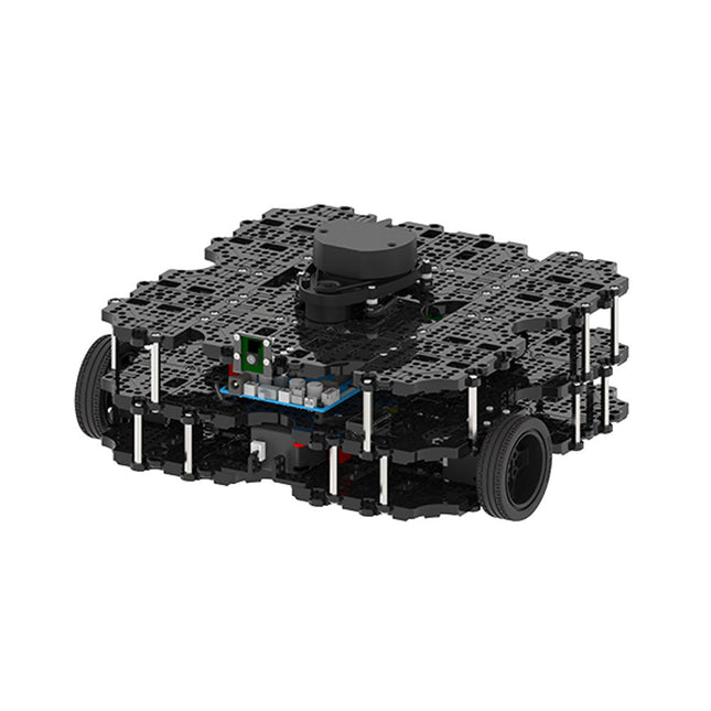
World’s Most Popular ROS Platform TurtleBot is the most popular open source robot for education and research. The new generation TurtleBot3 is a small, low cost, fully programmable, ROS based mobile robot. It is intended to be used for education, research, hobby and product prototyping. Affordable Cost TurtleBot was developed to meet the cost-conscious needs of schools, laboratories and companies. TurtleBot3 is the most affordable robot among the SLAM-able mobile robots equipped with a 360° Laser Distance Sensor LDS-01. ROS Standard The TurtleBot brand is managed by Open Robotics, which develops and maintains ROS. Nowadays, ROS has become the go-to platform for all the roboticists around the world. TurtleBot can be integrated with existing ROS-based robot components, but TurtleBot3 can be an affordable platform for whom want to get started learning ROS. Extensibility TurtleBot3 encourages users to customize its mechanical structure with some alternative options: open source embedded board (as a control board), computer and sensors. TurtleBot3 Waffle Pi is a two-wheeled differential drive type platform but it is able to be structurally and mechanically customized in many ways: Cars, Bikes, Trailers and so on. Extend your ideas beyond imagination with various SBC, sensors and motors on a scalable structure. Modular Actuator for Mobile Robot TurtleBot3 is able to get a precise spatial data by using 2 DYNAMIXEL’s in the wheel joints. DYNAMIXEL XM series can be operated by one of 6 operating modes (XL series: 4 operating modes): Velocity control mode for wheels, Torque control mode or Position control mode for joint, etc. DYNAMIXEL can be used even to make a mobile manipulator which is light but can be precisely controlled with velocity, torque and position control. DYNAMIXEL is a core component that makes TurtleBot3 perfect. It is easy to assemble, maintain, replace and reconfigure. Open Control Board for ROS The control board is open-sourced in hardware wise and in software wise for ROS communication. The open source control board OpenCR1.0 is powerful enough to control not only DYNAMIXEL’s but also ROBOTIS sensors that are frequently being used for basic recognition tasks in cost effective way. Various sensors such as Touch sensor, Infrared sensor, Color sensor and a handful more are available. The OpenCR1.0 has an IMU sensor inside the board so that it can enhance precise control for countless applications. The board has 3.3 V, 5 V, 12 V power supplies to reinforce the available computer device lineups. Open Source The hardware, firmware and software of TurtleBot3 are open source which means that users are welcomed to download, modify and share source codes. All components of TurtleBot3 are manufactured with injection molded plastic to achieve low cost, however, the 3D CAD data is also available for 3D printing. Specifications Maximum translational velocity 0.26 m/s Maximum rotational velocity 1.82 rad/s (104.27 deg/s) Maximum payload 30 kg Size (L x W x H) 281 x 306 x 141 mm Weight (+ SBC + Battery + Sensors) 1.8 kg Threshold of climbing 10 mm or lower Expected operating time 2h Expected charging time 2h 30m SBC (Single Board Computers) Raspberry Pi 4 (2 GB RAM) MCU 32-bit ARM Cortex-M7 with FPU (216 MHz, 462 DMIPS) Remote Controller RC-100B + BT-410 Set (Bluetooth 4, BLE) Actuator XL430-W210 LDS (Laser Distance Sensor) 360 Laser Distance Sensor LDS-01 or LDS-02
Camera Raspberry Pi Camera Module v2.1 IMU Gyroscope 3 AxisAccelerometer 3 Axis Power connectors 3.3 V/800 mA5 V/4 A12 V/1 A Expansion pins GPIO 18 pinsArduino 32 pin Peripheral 3x UART, 1x CAN, 1x SPI, 1x I²C, 5x ADC, 4x 5-pin OLLO DYNAMIXEL ports 3x RS485, 3x TTL Audio Several programmable beep sequences Programmable LEDs 4x User LED Status LEDs 1x Board status LED1x Arduino LED1x Power LED Buttons and Switches 2x Push buttons, 1x Reset button, 2x Dip switch Battery Lithium polymer 11.1 V 1800 mAh / 19.98 Wh 5C PC connection USB Firmware upgrade via USB / via JTAG Power adapter (SMPS) Input: 100-240 VAC 50/60 Hz, 1.5 A @maxOutput: 12 VDC, 5 A Downloads ROS Robot Programming GitHub E-Manual Community
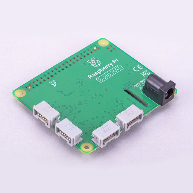
Build robust, intelligent machines that combine Raspberry Pi computing power with LEGO components.
The Raspberry Pi Build HAT provides four connectors for LEGO Technic motors and sensors from the SPIKE Portfolio. The available sensors include a distance sensor, a color sensor, and a versatile force sensor. The angular motors come in a range of sizes and include integrated encoders that can be queried to find their position.
The Build HAT fits all Raspberry Pi computers with a 40-pin GPIO header, including – with the addition of a ribbon cable or other extension device — Raspberry Pi 400. Connected LEGO Technic devices can easily be controlled in Python, alongside standard Raspberry Pi accessories such as a camera module.
Features
Controls up to 4 motors and sensors
Powers the Raspberry Pi (when used with a suitable external PSU)
Easy to use from Python on the Raspberry Pi
The Raspberry Pi Debug Probe is an all-in-one USB-to-debug kit that provides all the necessary hardware and cables for easy, solderless, plug-and-play debugging.
It features both a processor serial debug interface (by default the ARM Serial Wire Debug interface, but other interfaces can be supported) and an industry-standard UART interface. Both interfaces use the Raspberry Pi 3-pin debug connector.
It is designed to make it easy to debug and program Raspberry Pi Pico and RP2040 with a range of host platforms including Windows, Mac, and typical Linux computers.
While designed for use with Raspberry Pi products, the Debug Probe provides standard UART and CMSIS-DAP interfaces over USB, so it can also be used with other processors, or even just as a USB-to-UART cable. It works with OpenOCD and other tools that support CMSIS-DAP.
The Debug Probe is based on Raspberry Pi Pico hardware and runs the open source Raspberry Pi Pico Probe software. The firmware is updated in the same way as Raspberry Pi Pico firmware, so it is easy to keep the unit up to date with the latest firmware, or to use custom firmware.
Features
USB to ARM Serial Wire Debug (SWD) port
USB to UART bridge
Compatible with the CMSIS-DAP standard
Works with OpenOCD and other tools supporting CMSIS-DAP
Open source, easily upgradeable firmware
Specifications
Dimensions: 22 x 32 mm
Nominal I/O voltage: 3.3 V
Operating temperature: -20°C to +70°C
Included
1x Raspberry Pi Debug Probe
1x Plastic case
1x USB cable
3x Debug cables
3-pin JST connector to 3-pin JST connector cable
3-pin JST connector to 0.1-inch header (female)
3-pin JST connector to 0.1-inch header (male)
Downloads
Datasheet
3-pin Debug Connector
Schematics
Diagram
Latest Firmware
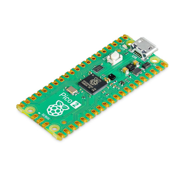
The Raspberry Pi Pico 2 is a new microcontroller board from the Raspberry Pi Foundation, based on the RP2350. It features a higher core clock speed, double the on-chip SRAM, double the on-board flash memory, more powerful Arm cores, optional RISC-V cores, new security features, and upgraded interfacing capabilities. The Raspberry Pi Pico 2 offers a significant boost in performance and features while maintaining hardware and software compatibility with earlier members of the Raspberry Pi Pico series.
The RP2350 provides a comprehensive security architecture built around Arm TrustZone for Cortex-M. It incorporates signed boot, 8 KB of antifuse OTP for key storage, SHA-256 acceleration, a hardware TRNG, and fast glitch detectors.
The unique dual-core, dual-architecture capability of the RP2350 allows users to choose between a pair of industry-standard Arm Cortex-M33 cores and a pair of open-hardware Hazard3 RISC-V cores. Programmable in C/C++ and Python, and supported by detailed documentation, the Raspberry Pi Pico 2 is the ideal microcontroller board for both enthusiasts and professional developers.
Specifications
CPU
Dual Arm Cortex-M33 or dual RISC-V Hazard3 processors @ 150 MHz
Memory
520 KB on-chip SRAM; 4 MB on-board QSPI flash
Interfaces
26 multi-purpose GPIO pins, including 4 that can be used for AD
Peripherals
2x UART
2x SPI controllers
2x I²C controllers
24x PWM channels
1x USB 1.1 controller and PHY, with host and device support
12x PIO state machines
Input power
1.8-5.5 V DC
Dimensions
21 x 51 mm
Downloads
Datasheet (Pico 2)
Datasheet (RP2350)
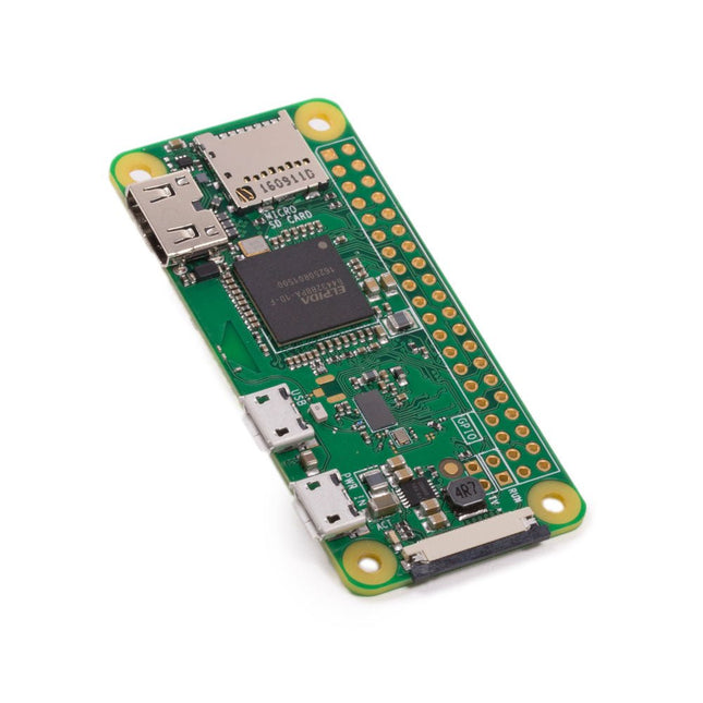
The Raspberry Pi Zero W extends the Raspberry Pi Zero family. The Raspberry Pi Zero W has all the functionality of the original Raspberry Pi Zero, but comes with added connectivity consisting of:
802.11 b/g/n wireless LAN
Bluetooth 4.1
Bluetooth Low Energy (BLE)
Other Features
1 GHz, single-core CPU
512 MB RAM
Mini HDMI and USB On-The-Go ports
Micro-USB power
HAT-compatible 40-pin header
Composite video and reset headers
CSI camera connector
Downloads
Mechanical Drawing
Schematics
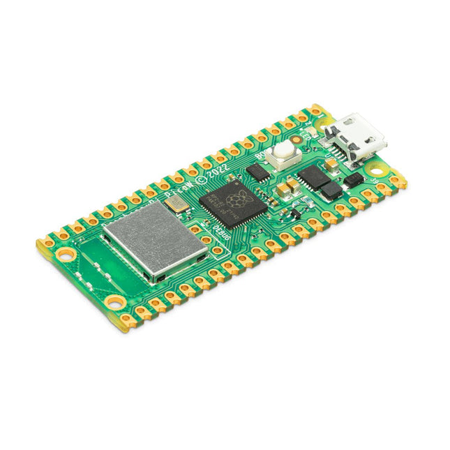
Raspberry Pi Pico W is a microcontroller board based on the Raspberry Pi RP2040 microcontroller chip.
The RP2040 microcontroller chip ('Raspberry Silicon') offers a dual-core ARM Cortex-M0+ processor (133 MHz), 256 KB RAM, 30 GPIO pins, and many other interface options. In addition, there is 2 MB of on-board QSPI flash memory for code and data storage.
Raspberry Pi Pico W has been designed to be a low cost yet flexible development platform for RP2040 with a 2.4 GHz wireless interface using an Infineon CYW43439. The wireless interface is connected via SPI to the RP2040.
Features of Pico W
RP2040 microcontroller with 2 MB of flash memory
On-board single-band 2.4 GHz wireless interfaces (802.11n)
Micro USB B port for power and data (and for reprogramming the flash)
40 pin 21 x 51 mm 'DIP' style 1 mm thick PCB with 0.1' through-hole pins also with edge castellations
Exposes 26 multi-function 3.3 V general purpose I/O (GPIO)
23 GPIO are digital-only, with three also being ADC capable
Can be surface mounted as a module
3-pin ARM serial wire debug (SWD) port
Simple yet highly flexible power supply architecture
Various options for easily powering the unit from micro USB, external supplies or batteries
High quality, low cost, high availability
Comprehensive SDK, software examples and documentation
Features of the RP2040 microcontroller
Dual-core cortex M0+ at up to 133 MHz
On-chip PLL allows variable core frequency
264 kByte multi-bank high performance SRAM
External Quad-SPI Flash with eXecute In Place (XIP) and 16 kByte on-chip cache
High performance full-crossbar bus fabric
On-board USB1.1 (device or host)
30 multi-function general purpose I/O (four can be used for ADC)
1.8-3.3 V I/O voltage
12-bit 500 ksps analogue to digital converter (ADC)
Various digital peripherals
2x UART, 2x I²C, 2x SPI, 16x PWM channels
1x timer with 4 alarms, 1x real time clock
2x programmable I/O (PIO) blocks, 8 state machines in total
Flexible, user-programmable high-speed I/O
Can emulate interfaces such as SD card and VGA
Note: Raspberry Pi Pico W I/O voltage is fixed at 3.3 V.
Downloads
Datasheet
Specifications of 3-pin Debug Connector