Search results for "projekte OR mit OR dem OR rfid OR starterkit OR fur OR arduino OR pdf"
-
Elektor Digital Elektor Arduino Guest Edition 2022 (PDF) EN
Elektor GREEN and GOLD members can download their digital edition here. Not a member yet? Click here. Arduino Portenta Machine Control and Arduino Portenta H7A CAN-to-MQTT Gateway Demo Project Unboxing the Elektor LCR Meter with David Cuartielles MicroPython Enters the World of Arduino Connected Projects, SimplifiedDive Into the Arduino Cloud Introduction to TinyMLBig Is Not Always Better Arduino K-Way Writing Arduino Sketches Just Got Better Get to Know Arduino Getting Started with the Portenta X8Manage Software Securely with Containers Build, Deploy, and Maintain Scalable, Secure ApplicationsWith Arduino Portenta X8 Featuring NXP’s i.MX 8M Mini Applications Processor and EdgeLock SE050 Secure Element How I Automated My HomeArduino CEO Fabio Violante Shares Solutions Altair 8800 SimulatorHardware Simulation of a Vintage Computer MS-DOS on the Portenta H7Run Old-School Software on Contemporary Hardware Grow It YourselfA Digitally Controlled, Single-Box Solution for Indoor Farming Save the Planet With Home Automation?MQTT on the Arduino Nano RP2040 Connect Go Professional with Arduino Pro Smart Ovens Take a Leap Into the Future Tagvance Builds Safer Construction Sites with Arduino Santagostino Breathes Easywith Remote Monitoring that Leverages AI for Predictive Maintenance Security Flies High with RIoT Secure’s MKR-Based Solution Open-Source Brings a New Generation of Water Management to the World SensoDetect Deforestation with Sound Analysis The Mozzi Arduino Library for Sound SynthesisInsights from Tim Barrass The New Portenta X8 (with Linux!) and Max Carrier Redefine What’s Possible How Using Arduino Helps Students Build Future Skills Must-Haves for Your Electronics Workspace The Importance of Robotics in Education Dependable IoT Based Upon LoRa Unboxing the Portenta Machine Control 8-Bit Gaming with Arduboy Reducing Water Usage at Horseback Riding TracksAn IoT to Constantly Monitor Soil Humidity and Temperature Levels The Panettone ProjectA sourdough starter management and maintenance system Supporting Arduino Resellers Space Invaders with Arduino Art with ArduinoInspiring Insights from Artists and Designers Arduino Product Catalogue The Future of Arduino
€ 7,50
-
Elektor Digital Elektor Special: Introduction to Electronics with Arduino (PDF)
Although the Arduino isn’t a novelty any longer, there are still many beginners who want to try programming and development with a microcontroller, and to them, it is all new. All beginnings can be difficult, though they should be light and enjoyable. You do not need much or expensive equipment for the examples. The circuits are built on a small breadboard, and, if necessary, connected to an Arduino Uno, which you can program on a Windows PC. You will find clear examples of how to build all circuits, ensuring easy and error-free reproduction. Projects Discussed Current & Voltage – How it all began Arduino Hardware Arduino Programming The Electrical Circuit Measuring with the Multimeter Circuit Diagrams and Breadboards Creating Circuit Diagrams Breadboard Views with Fritzing Online Circuit Simulation Indispensable: Resistors (Part 1) Hands-on with Resistors (Part 2) Variable Resistors Diodes: One-way Street for Current The Transistor Switch Electromagnetism Relays and Motors op-amps: Operational Amplifiers Capacitors The NE555 Timer PWM and Analogue Values with Arduino 7-Segment Temperature Display Introduction to Soldering and LCDs
€ 11,95
Members: € 10,76
-
Elektor Digital Elektor Special: Arduino Shields (PDF) EN
Make your project dreams come true: an odometer for the hamster wheel, a fully automatic control of your ant farm with web interface, or the Sandwich-O-Mat – a machine that toasts and grills sandwiches of your choice. With the Arduino and the DIY or Maker movement, not only did entry into microcontroller programming become child's play, but a second development also took place: Resourceful developers brought small boards – so-called shields or modules – to the market, which greatly simplified the use of additional hardware. The small modules contain all the important electronic parts to be connected to the microcontroller with a few plug-in cables, eliminating the need for a fiddly and time-consuming assembly on the plug-in board. In addition, it is also possible to handle tiny components that do not have any connecting legs (so-called SMDs). Projects Discussed Arduino seeks connection BMP and introduction to libraries, I²C Learn I/O basics with the multi-purpose shield I²C LCD adapter and DOT matrix displays LCD keypad shield Level converter W5100: Internet connection I/O expansion shield Relays and solid-state relays The multi-function shield: A universal control unit Connecting an SD card reader via SPI Keys and 7-segment displays 16-bit ADC MCP4725 DAC 16-way PWM servo driver MP3 player GPS data logger using an SD card Touch sensor Joystick SHT31: Temperature and humidity VEML6070 UV-A sensor VL53L0X time-of-flight Ultrasonic distance meter MAX7219-based LED DOT matrix display DS3231 RTC Port expander MCP23017 433 MHz radio MPU-650 gyroscope ADXL345 accelerometer WS2812 RGB LEDs Power supply MQ-xx gas sensors CO2 gas sensor ACS712 current sensor INA219 current sensor L298 motor driver MFRC522 RFID 28BYJ-48 stepper motor TMC2209 silent step stick X9C10x digital potentiometer ST7735 in a color TFT display e-Paper display Bluetooth Geiger counter SIM800L GSM module I²C multiplexer Controller Area Network
€ 11,95
Members: € 10,76
-

Elektor Labs Elektor Arduino MultiCalculator
The Elektor MultiCalculator Kit is an Arduino-based multifunction calculator that goes beyond basic calculations. It offers 22 functions including light and temperature measurement, differential temperature analysis, and NEC IR remote control decoding. The Elektor MultiCalculator is a handy tool for use in your projects or for educational purposes. The kit features a Pro Mini module as the computing unit. The PCB is easy to assemble using through-hole components. The enclosure consists of 11 acrylic panels and mounting materials for easy assembly. Additionally, the device is equipped with a 16x2 alphanumeric LCD, 20 buttons, and temperature sensors. The Elektor MultiCalculator is programmable with the Arduino IDE through a 6-way PCB header. The available software is bilingual (English and Dutch). The calculator can be programmed with a programming adapter, and it is powered through USB-C. Modes of Operation Calculator 4-Ring Resistor Code 5-Ring Resistor Code Decimal to Hexadecimal and Character (ASCII) conversion Hexadecimal to Decimal and Character (ASCII) conversion Decimal to Binary and Character (ASCII) conversion Binary to Decimal and Hexadecimal conversion Hz, nF, capacitive reactance (XC) calculation Hz, µH, inductive reactance (XL) calculation Resistance calculation of two resistors connected in parallel Resistance calculation of two resistors connected in series Calculation of unknown parallel resistor Temperature measurement Differential temperature measurement T1&T2 and Delta (δ) Light measurement Stopwatch with lap time function Item counter NEC IR remote control decoding AWG conversion (American Wire Gauge) Rolling Dice Personalize startup message Temperature calibration Specifications Menu languages: English, Dutch Dimensions: 92 x 138 x 40 mm Build time: approx. 5 hours Included PCB and though-hole components Precut acrylic sheets with all mechanical parts Pro Mini microcontroller module (ATmega328/5 V/16 MHz) Programming adapter Waterproof temperature sensors USB-C cable Downloads Software
€ 49,95€ 39,95
Best Price
-

Elektor Academy Pro Arduino (Programming Course)
This complete Arduino Uno-based microcontroller programming course features a textbook, a component kit, hands-on projects, and a comprehensive online course with simulations. It is ideal for step-by-step learning of embedded systems programming with Arduino using a practical, hands-on approach. A Practical Introduction to Embedded Systems with the Arduino Uno This course is designed for people who are new to embedded systems and looking for a structured, example-driven way to get started. A kit of parts comprising LEDs and resistors, switches, sensors and actuators, displays, a breadboard and wires, and more is included. These are used in the course to illustrate example applications. No prior experience with Arduino or embedded development is required. Each section features hands-on examples and mini projects designed to reinforce key concepts and inspire deeper exploration. By the end of the course, you’ll be able not only to reproduce the examples but also to build on them with your own ideas and applications. What Will You Learn? Microcontroller programming with Arduino using the Uno R3 board Working with Digital I/O, read buttons and encoders, control LEDs and relays Read analog inputs, voltages, and analog sensors Generating analog output signals and PWM Use serial communication like UART, I²C and SPI to control displays and read digital sensors and SD cards Managing time Working with interrupts Real-time sensor input and control via buttons, LEDs, and displays Control actuators like relays and servo motors Who Is It For? Students and self-learners exploring embedded systems Makers and IoT enthusiasts looking to improve their hardware skills Educators and trainers seeking ready-to-teach material What's Inside the Box? Access to the full course on the Elektor Academy Pro Learning Platform Uno R3 microcontroller board + USB cable Book: Programming Microcontrollers in C/C++ Using Arduino Downloadable project files for every module Component Box: 2× LED, red, 5 mm LED, green, 5 mm 3× Resistor, 470 Ω, 0.25 W LDR Potentiometer, 10 kΩ, linear Pushbutton Rotary encoder module Relay module DHT22 Humidity & Temperature Sensor TM1637-compatible 4-digit 7-segment display MPU-6050 IMU with headers SSD1306-compatible I²C OLED display Micro SD card adapter with header Buzzer SG90 Micro Servo ILI9341-compatible SPI 240×320 TFT display 20× Jumper wires Breadboard All Programming Courses (and differences in content) Course Arduino Raspberry Pi Pico with Arduino C/C++ ESP32 with Arduino C/C++ Raspberry Pi Pico with MicroPython ESP32 with MicroPython Online Course Access to Arduino Course Access to Pico with Arduino C/C++ Course Access to ESP32 with Arduino C/C++ Course Access to Pico with MicroPython Course Access to ESP32 with MicroPython Course Board Uno R3 Raspberry Pi Pico ESP32 Raspberry Pi Pico ESP32 Book Programming Microcontrollers in C/C++ Using Arduino Programming Microcontrollers in C/C++ Using Arduino Programming Microcontrollers in C/C++ Using Arduino Programming Microcontrollers in MicroPython Programming Microcontrollers in MicroPython Kit 40-piece Component Box 40-piece Component Box 40-piece Component Box 40-piece Component Box 40-piece Component Box
€ 69,95
Members: € 62,96
-

Elektor Publishing Mastering the Arduino Uno R4
Programming and Projects for the Minima and WiFi Based on the low-cost 8-bit ATmega328P processor, the Arduino Uno R3 board is likely to score as the most popular Arduino family member, and this workhorse has been with us for many years. Eleven years later, the long-overdue successor, the Arduino Uno R4, was released. It is built around a 48 MHz, 32-bit Arm Cortex-M4 microcontroller and provides significantly expanded SRAM and Flash memory. Additionally, a higher-precision ADC and a new DAC are added to the design. The Uno R4 board also supports the CAN Bus with an interface. Two versions of the board are available: Uno R4 Minima, and Uno R4 WiFi. This book is about using these new boards to develop many different and interesting projects with just a handful of parts and external modules. All projects described in the book have been fully tested on the Uno R4 Minima or the Uno R4 WiFi board, as appropriate. The project topics include the reading, control, and driving of many components and modules in the kit as well as on the relevant Uno R4 board, including LEDs 7-segment displays (using timer interrupts) LCDs Sensors RFID Reader 4x4 Keypad Real-time clock (RTC) Joystick 8×8 LED matrix Motors DAC (Digital-to-analog converter) LED matrix WiFi connectivity Serial UART CAN bus Infrared controller and receiver Simulators … all in creative and educational ways with the project operation and associated software explained in great detail.
€ 39,95
Members: € 35,96
-

Elektor Bundles Arduino UNO Q (Bundle)
This bundle includes the Arduino UNO Q (2 GB) and the new book "Arduino UNO Q and AI". The Arduino UNO Q is the first UNO board with a hybrid dual-brain architecture, combining a powerful Linux processor with a real-time microcontroller – bringing advanced computing and precise control together on one board. Powered by a Qualcomm Dragonwing QRB2210 MPU running Debian Linux and a STM32U585 MCU for real-time tasks, the UNO Q is built for next-generation applications. From Edge Computing and AI to robotics and automation, it delivers high performance without sacrificing ease of use. Simply connect your peripherals and get started – no extra hardware required. Features Dual-core architecture: Linux MPU + real-time MCU Qualcomm Dragonwing QRB2210 with Debian Linux support STM32U585 microcontroller for deterministic control Runs Arduino sketches via Zephyr OS Ideal for AI, IoT, robotics, and industrial projects Specifications Microprocessor (MPU) Qualcomm Dragonwing QRB2210:Quad-core Arm Cortex-A53 @ 2.0 GHzAdreno GPU 3D graphics accelerator2× ISP (13 MP + 13 MP or 25 MP) @ 30 fps Microcontroller (MCU) STM32U585Arm Cortex-M33 up to 160 MHz2 MB flash memory786 KB SRAM RAM 2 GB LPDDR4 Power Supply From USB-C connector 5 V max at 3 AInput Voltage (VIN): 7-24 V Storage 16 GB eMMC USB 1× USB-C port with host/device role switching, power role switch and video output Connectivity Wi-Fi 5 (2.4/5 GHz) with onboard antennaBluetooth 5.1 with onboard antenna Interfaces I²C/I³CSPIPWMCANUARTPSSIGPIOJTAGADC Video Video output support via USB-CMIPI DSI pins on JMEDIA header Extra 4× RGB user-controllable LEDs8×13 Blue LED Matrix1× Qwiic connector voltage 3V3, I²C1× User push-buttonJCTL: MPU Remote Debug connector Audio Microphone IN / Headphone OUT / Line OUT on JMISC MPU Operating System Linux Debian OS with upstream support Real-time Operating System Arduino Core on Zephyr OS Containerization Docker and Docker Compose support Support Operating Systems for Arduino App Lab Windows: Windows 10 or later (64-bit)macOS: macOS 11 or later (64-bit)Linux: Ubuntu 22.04 or later, and Debian Trixie (64-bit) Dimensions 68.85 × 53.34 mm (UNO form factor) Downloads Datasheet User Manual Pinout Schematics Book: Arduino UNO Q and AI – Learn to Build Intelligent Embedded Systems Build smarter embedded systems with Arduino UNO Q. This book gives you the tools, knowledge, and confidence to turn ideas into intelligent, working solutions using the Arduino UNO Q platform. Discover how to build intelligent embedded systems with the Arduino UNO Q and AI. Unlock the full potential of the Arduino UNO Q, a next-generation platform that combines the real-time power of the STM32U585 microcontroller with the flexibility of a Qualcomm Dragonwing QRB2210 microprocessor. Learn how to rapidly prototype real-world applications using the Arduino IDE for low-level embedded control and Python in Arduino App Lab for high-level development. Build confidence through hands-on projects that guide you step by step from basic board features to complete working systems. Explore ready-to-use, AI based Arduino App Lab examples and see how they can jump-start your development and reduce time to deployment. Step into the world of Edge AI with a clear, practical introduction to Edge Impulse Studio—no prior AI experience required. Follow a complete, real-world workflow to create a Keyword Spotting AI application, covering data collection, model training, optimization, and on-device inference using the Edge Impulse Studio. Bridge the gap between embedded systems and machine learning and learn how to bring intelligence directly onto your hardware. Perfect for embedded engineers, educators, students, and makers looking to stay ahead in AI-enabled product development. This bundle contains: Arduino UNO Q (2 GB) (normal price: €50) Book: Arduino UNO Q and AI (normal price: €35)
€ 84,95€ 69,95
Best Price
-

Elektor Classics The Elektor Arduino Collection (USB Stick)
This USB Stick contains more than 300 Arduino-related articles published in Elektor Magazine. The content includes both background articles and projects on the following topics: Software & hardware development: Tutorials on Arduino software development using Arduino IDE, Atmel Studio, Shields, and essential programming concepts. Learning: The Microcontroller Bootcamp offers a structured approach to programming embedded systems. Data acquisition & measurement: Projects such as a 16-bit data logger, lathe tachometer, and an AC grid analyzer for capturing and analyzing real-time signals. Wireless communication: Learn how to implement wireless networks, create an Android interface, and communicate effectively with microcontrollers. Robotics and automation: This covers the Arduino Nano Robot Controller, supporting boards for automation, and explores various Arduino shields to enhance functionality. Self-build projects: Unique projects such as laser projection, Numitron clock and thermometer, ELF receiver, Theremino, and touch LED interfaces highlight creative applications. Whether you're a beginner or an experienced maker, this collection is a valuable resource for learning, experimenting, and pushing the boundaries of Arduino technology.
€ 49,95€ 34,95
Best Price
-
Elektor Publishing Coding Modbus TCP/IP for Arduino
Example projects with Node-RED, MQTT, WinCC SCADA, Blynk, and ThingSpeak This comprehensive guide unlocks the power of Modbus TCP/IP communication with Arduino. From the basics of the Modbus protocol right up to full implementation in Arduino projects, the book walks you through the complete process with lucid explanations and practical examples. Learn how to set up Modbus TCP/IP communication with Arduino for seamless data exchange between devices over a network. Explore different Modbus functions and master reading and writing registers to control your devices remotely. Create Modbus client and server applications to integrate into your Arduino projects, boosting their connectivity and automation level. With detailed code snippets and illustrations, this guide is perfect for beginners and experienced Arduino enthusiasts alike. Whether you‘re a hobbyist looking to expand your skills or a professional seeking to implement Modbus TCP/IP communication in your projects, this book provides all the knowledge you need to harness the full potential of Modbus with Arduino. Projects covered in the book: TCP/IP communication between two Arduino Uno boards Modbus TCP/IP communication within the Node-RED environment Combining Arduino, Node-RED, and Blynk IoT cloud Interfacing Modbus TCP/IP with WinCC SCADA to control sensors Using MQTT protocol with Ethernet/ESP8266 Connecting to ThingSpeak IoT cloud using Ethernet/ESP8266
€ 39,95
Best Price
-
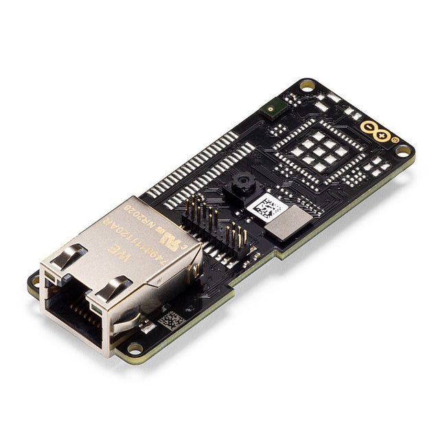
Arduino Arduino Pro Portenta Vision Shield (Ethernet)
The Arduino Pro Portenta Vision Shield brings industry-rated features to your Portenta. This hardware add-on will let you run embedded computer vision applications, connect wirelessly or via Ethernet to the Arduino Cloud or your own infrastructure, and activate your system upon the detection of sound events. Features 324x324 pixels camera sensor: use one of the cores in Portenta to run image recognition algorithms using the OpenMV for Arduino editor 100 Mbps Ethernet connector: get your Portenta H7 connected to the wired Internet 2 onboard microphones for directional sound detection: capture and analyse sound in real-time JTAG connector: perform low-level debugging of your Portenta board or special firmware updates using an external programmer SD-Card connector: store your captured data in the card, or read configuration files The Vision Shield has been designed to fit on top of the Arduino Portenta family. The Portenta boards feature multicore 32-bit ARM Cortex processors running at hundreds of megahertz, with megabytes of program memory and RAM. Portenta boards come with WiFi and Bluetooth. Embedded Computer Vision Made Easy Arduino has teamed up with OpenMV to offer you a free license to the OpenMV IDE, an easy way into computer vision using MicroPython as a programming paradigm. Download the OpenMV for Arduino Editor from our professional tutorials site and browse through the examples we have prepared for you inside the OpenMV IDE. Companies across the whole world are already building their commercial products based on this simple-yet-powerful approach to detect, filter, and classify images, QR codes, and others. Debugging With Professional Tools Connect your Portenta H7 to a professional debugger through the JTAG connector. Use professional software tools like the ones from Lauterbach or Segger on top of your board to debug your code step by step. The Vision Shield exposes the required pins for you to plug in your external JTAG. Camera Himax HM-01B0 camera module Resolution 320 x 320 active pixel resolution with support for QVGA Image sensor High sensitivity 3.6μ BrightSense pixel technology Microphone 2 x MP34DT05 Length 66 mm Width 25 mm Weight 11 gr For more information, check out the tutorials provided by Arduino here.
€ 69,95€ 19,95
Best Price
-
Elektor Publishing FreeRTOS for ESP32-Arduino
Practical Multitasking Fundamentals Programming embedded systems is difficult because of resource constraints and limited debugging facilities. Why develop your own Real-Time Operating System (RTOS) as well as your application when the proven FreeRTOS software is freely available? Why not start with a validated foundation? Every software developer knows that you must divide a difficult problem into smaller ones to conquer it. Using separate preemptive tasks and FreeRTOS communication mechanisms, a clean separation of functions is achieved within the entire application. This results in safe and maintainable designs. Practicing engineers and students alike can use this book and the ESP32 Arduino environment to wade into FreeRTOS concepts at a comfortable pace. The well-organized text enables you to master each concept before starting the next chapter. Practical breadboard experiments and schematics are included to bring the lessons home. Experience is the best teacher. Each chapter includes exercises to test your knowledge. The coverage of the FreeRTOS Application Programming Interface (API) is complete for the ESP32 Arduino environment. You can apply what you learn to other FreeRTOS environments, including Espressif’s ESP-IDF. The source code is available from GitHub. All of these resources put you in the driver’s seat when it is time to develop your next uber-cool ESP32 project. What you will learn: How preemptive scheduling works within FreeRTOS The Arduino startup “loopTask” Message queues FreeRTOS timers and the IDLE task The semaphore, mutex, and their differences The mailbox and its application Real-time task priorities and its effect Interrupt interaction and use with FreeRTOS Queue sets Notifying tasks with events Event groups Critical sections Task local storage The gatekeeper task
€ 44,95
Members: € 40,46
-
Elektor Publishing Arduino for Radio Amateur Applications
Program and build Arduino-based ham station utilities, tools, and instruments In addition to a detailed introduction to the exciting world of the Arduino microcontroller and its many variants, this book introduces you to the shields, modules, and components you can connect to the Arduino. Many of these components are discussed in detail and used in the projects included in this book to help you understand how these components can be incorporated into your own Arduino projects. Emphasis has been placed on designing and creating a wide range of amateur radio-related projects that can easily be built in just a few days. This book is written for ham radio operators and Arduino enthusiasts of all skill levels, and includes discussions about the tools, construction methods, and troubleshooting techniques used in creating amateur radio-related Arduino projects. The book teaches you how to create feature-rich Arduino-based projects, with the goal of helping you to advance beyond this book, and design and build your own ham radio Arduino projects. In addition, this book describes in detail the design, construction, programming, and operation of the following projects: CW Beacon and Foxhunt Keyer Mini Weather Station RF Probe with LED Bar Graph DTMF Tone Encoder DTMF Tone Decoder Waveform Generator Auto Power On/Off Bluetooth CW Keyer Station Power Monitor AC Current Monitor This book assumes a basic knowledge of electronics and circuit construction. Basic knowledge of how to program the Arduino using its IDE will also be beneficial.
€ 39,95
Members: € 35,96


