Add colors to your projects with this collection of red, green, yellow, blue and white LEDs. They come with various current limiting resistors in order to protect the parts and control the brightness.Included
10 mm LEDs
1x red
1x green
1x yellow
1x blue
1x white
5 mm LEDs
5x red
5x green
5x yellow
5x blue
5x white
3 mm LEDs
5x red
5x green
5x yellow
5x blue
5x white
25x 330 Ω resistors
10x 1 kΩ resistors
10x 10 kΩ resistors
10x 100 kΩ resistors
10x 1 MΩ resistors
The Pimoroni Explorer Starter Kit is an electronic adventure playground for physical computing based on the RP2350 chip. It includes a 2.8-inch LCD screen, a speaker, a mini breadboard and much more. It's ideal for tinkering, experiments, and building small prototypes.
Features
Mini breadboard for wiring up components
Servo headers
Analog inputs
Built-in speaker
Plenty of general purpose inputs/outputs
Connectors for attaching crocodile leads
Qw/ST connectors for attaching I²C breakouts
Specifications
Powered by RP2350B (Dual Arm Cortex-M33 running at up to 150 MHz with 520 KB of SRAM)
16 MB of QSPI flash supporting XiP
2.8" IPS LCD screen (320 x 240 pixels)
Driver IC: ST7789V
Luminance: 250 cd/m²
Active area: 43.2 x 57.5 mm
USB-C connector for programming and power
Mini breadboard
Piezo speaker
6x user-controllable switches
Reset and boot buttons
Easy access GPIO headers (6x GPIOs and 3x ADCs, plus 3.3 V power and grounds)
6x Crocodile clip terminals (3x ADCs, plus 3.3 V power and grounds)
4x 3-pin servo outputs
2x Qw/ST (Qwiic/STEMMA QT) connector
2-pin JST-PH connector for adding a battery
Lanyard slot!
Includes 2x desktop stand feet
Fully-assembled (no soldering required)
Programmable with C/C++ or MicroPython
Included
1x Pimoroni Explorer
1x Multi-Sensor Stick – a fancy new all-in-one super sensor suite for environmental, light and movement sensing
Selection of different colored LEDs to get blinky with (including red, yellow, green, blue, white and RGB)
1x Potentiometer (for analog amusements)
3x 12 mm switches with different coloured caps
2x Continuous rotation servos
2x 60 mm wheels for attaching to your servos
1x AAA battery holder (batteries not included)
1x Velcro to stick the battery holder to the back of Explorer
20x Pin to pin and 20x pin to socket jumper wires for making connections on your breadboard
1x Qw/ST cable to plug in the Multi-Sensor Stick
1x Silicon USB-C cable
Downloads
GitHub
Schematic
With a 6x20 grid of 2.54 mm spaced holes for easy soldering and labelled Pico pins so you know what's what, Pico Proto is perfect for when you're happy with your breadboard project and want to give it a secure, smart and compact long-term home.
Pico Proto doesn't come with any headers attached, so you will need to either solder it directly to your Pico's male header pins (for a permanent, but super slim sandwich) or solder it to some female header.
Features
40 2.54 mm spaced holes for attaching to your Pico.
120 2.54 mm spaced holes (6x20 grid) for attaching other things
Compatible with Raspberry Pi Pico.
Dimensions: approx 51 x 25 x 1 mm (L x W x H)
Raspberry Pi Pico Wireless Pack attaches to the back of your Pico and uses an ESP32 chip to let your Pico connect to 2.4 GHz wireless networks and transfer data. There's a microSD card slot for if you want to store lots of data locally as well as a RGB LED (for status updates) and a button (useful for things like enabling/disabling Wi-Fi).
Great for quickly adapting an existing Pico project to have wireless functionality, Raspberry Pi Pico Wireless Pack would come in handy for sending sensor data into home automation systems or dashboards, for hosting a web page from a matchbox or for letting your Pico interact with online APIs.
Features
ESP32-WROOM-32E module for wireless connectivity (connected via SPI) (datasheet)
1x Tactile button
RGB LED
Micro-SD card slot
Pre-soldered female headers for attaching your Raspberry Pi Pico
Fully assembled
No soldering required (as long as your Pico has header pins attached)
Compatible with Raspberry Pi Pico
Dimensions: approx 53 x 25 x 11 mm (L x W x H, including headers and components)
C++ and MicroPython libraries
Inventor 2040 W is a multi-talented board that does (almost) everything you might want a robot, prop or other mechanical thing to do. Drive a couple of fancy motors with encoders attached? Yep! Add up to six servos? Sure? Attach a little speaker so you can make noise? No problem! It's also got a battery connector so you can power your inventions from AA/AAA or LiPo batteries and carry your miniature automaton/animated top hat/treasure chest that growls at your enemies around with you untethered.
You also get a ton of options for hooking up sensors and other gubbins – there's two Qw/ST connectors (and an unpopulated Breakout Garden slot) for attaching breakouts, three ADC pins for analog sensors, photoresistors and such, and three spare digital GPIO you could use for LEDs, buttons or digital sensors. Speaking of LEDs, the board features 12 addressable LEDs (AKA Neopixels) – one for each servo and GPIO/ADC channel.
Features
Raspberry Pi Pico W Aboard
Dual Arm Cortex M0+ running at up to 133 Mhz with 264 kB of SRAM
2 MB of QSPI flash supporting XiP
Powered and programmable by USB micro-B
2.4 GHz wireless
2 JST-SH connectors (6 pin) for attaching motors
Dual H-Bridge motor driver (DRV8833)
Per motor current limiting (425 mA)
Per motor direction indicator LEDs
2 pin (Picoblade-compatible) connector for attaching speaker
JST-PH (2 pin) connector for attaching battery (input voltage 2.5-5.5 V)
6 sets of header pins for connecting 3 pin hobby servos
6 sets of header pins for GPIO (3 of which are ADC capable)
12x addressable RGB LEDs/Neopixels
User button
Reset button
2x Qw/ST connectors for attaching breakouts
Unpopulated headers for adding a Breakout Garden slot
Fully assembled
No soldering required (unless you want to add the Breakout Garden slot).
C/C++ and MicroPython libraries
Schematic
Downloads
Download pirate-brand MicroPython
Getting Started with Raspberry Pi Pico
Motor function reference
Servo function reference
MicroPython examples
C++ examples
Pico Breakout Garden Base sits underneath your Pico and lets you connect up to six of our extensive selection of Pimoroni breakouts to it. Whether it's environmental sensors so you can keep track of the temperature and humidity in your office, a whole host of little screens for important notifications and readouts, and, of course, LEDs. Scroll down for a list of breakouts that are currently compatible with our C++/MicroPython libraries!As well as a labelled landing area for your Pico, there's also a full set of broken out Pico connections, in case you need to attach even more sensors, wires, and circuitry. We've thrown in some rubber feet to keep the base nice and stable and to stop it from scratching your desk, or there are M2.5 mounting holes at the corners so that you can bolt it onto a solid surface if you prefer.The six sturdy black slots are edge connectors that connect the breakouts to the pins on your Pico. There's two slots for SPI breakouts, and four slots for I²C breakouts. Because I²C is a bus, you can use multiple I²C devices at the same time, providing they don't have the same I²C address (we've made sure that all of our breakouts have different addresses, and we print them on the back of the breakouts so they're easy to find).As well as being a handy way to add functionality to your Pico, Breakout Garden is also very useful for prototyping projects without the need for complicated wiring, soldering, or breadboards, and you can grow or change up your setup at any time.Features
Six sturdy edge-connector slots for breakouts
4x I²C slots (5 pins)
2x SPI slot (7 pins)
Landing area with female headers for Raspberry Pi Pico
0.1” pitch, 5 or 7 pin connectors
Broken-out pins
Reverse polarity protection (built into breakouts)
99% assembled – just need to stick on the feet!
Compatible with Raspberry Pi Pico
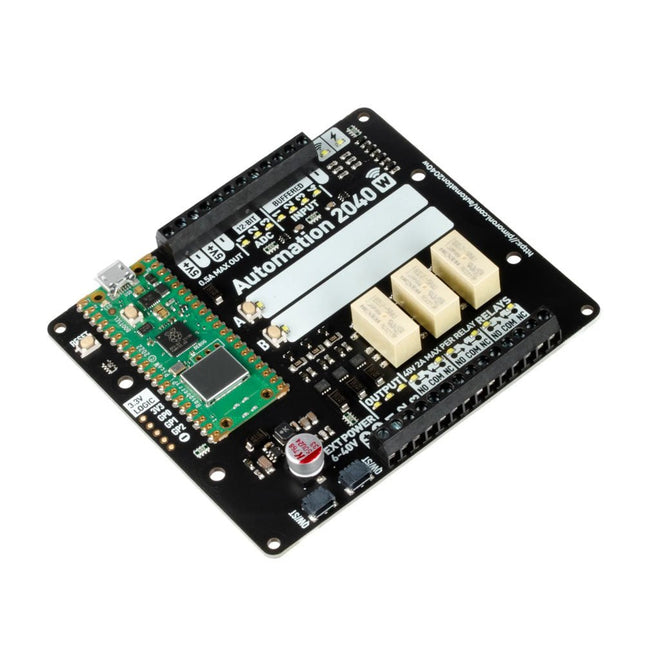
An all-in-one, Pico W powered industrial/automation controller with 2.46 GHz wireless connectivity, relays and a plethora of inputs and outputs. Compatible with 6 V to 40 V systems.
Automation 2040 W is a Pico W / RP2040 powered monitoring and automation board. It contains all the great features from the Automation HAT (relays, analog channels, powered outputs and buffered inputs) but now in a single compact board and with an extended voltage range so you can use it with more devices. Great for controlling fans, pumps, solenoids, chunky motors, electronic locks or static LED lighting (up to 40 V).
All the channels (and the buttons) have an associated indicator LED so you can see at a glance what's happening with your setup, or test your programs without having hardware connected.
Features
Raspberry Pi Pico W Aboard
Dual Arm Cortex M0+ running at up to 133 Mhz with 264 kB of SRAM
2 MB of QSPI flash supporting XiP
Powered and programmable by USB micro-B
2.4 GHz wireless
3x 12-bit ADC inputs up to 40 V
4x digital inputs up to 40 V
3x digital sourcing outputs at V+ (supply voltage)
4 A max continuous current
2 A max current at 500 Hz PWM
3x relays (NC and NO terminals)
2 A up to 24 V
1 A up to 40 V
3.5 mm screw terminals for connecting inputs, outputs and external power
2x tactile buttons with LED indicators
Reset button
2x Qw/ST connectors for attaching breakouts
M2.5 mounting holes
Fully assembled
No soldering required.
C/C++ and MicroPython libraries
Schematic
Dimensional drawing
Power
Board is compatible with 12 V, 24 V and 36 V systems
Requires supply 6-40 V
Can provide 5 V up to 0.5 A for lower voltage applications
Software
Pirate-brand MicroPython
Getting Started with Raspberry Pi Pico
MicroPython examples
MicroPython function reference
C++ examples
C++ function reference
Getting Started with Automation 2040 W
Thanks to its six sturdy slots, Breakout Garden enables the users to simply plug and play with various tiny breakout board.
Just insert one or more boards into the slots in the Breakout Garden HAT and you’re ready to go. The mini breakouts feel secure enough in the edge-connector slots and are very unlikely to fall out.
There are a number of useful pins along the top of Breakout Garden, which lets you connect other devices and integrate them into your project.
You shouldn't be worried if you insert a board the wrong way thanks to provided reverse polarity protection. It doesn't matter which slot you use for each breakout either, because the I²C address of the breakout will be recognised by the software and it'll detect them correctly in case you move them around.
Features
Six sturdy edge-connector slots for Pimoroni breakouts
0.1” pitch, 5 pin connectors
Broken-out pins (1 × 10 strip of male header included)
Standoffs (M2.5, 10 mm height) included to hold your Breakout Garden securely
Reverse polarity protection (built into breakouts)
HAT format board
Compatible with Raspberry Pi 3 B+, 3, 2, B+, A+, Zero, and Zero W
It's suggested using the included standoffs to attache Breakout Garden to your Raspberry Pi.
Software
Breakout Garden doesn't require any software of its own, but each breakout you use will need a Python library. On the Breakout Garden GitHub page you'll find an automatic installer, which will install the appropriate software for a given breakout. There are also some examples that show you what else you can do with Breakout Garden.
Maker Line is a line sensor with 5 x IR sensors array that is able to track line from 13 mm to 30 mm width.
The sensor calibration is also simplified. There is no need to adjust the potentiometer for each IR sensor. You just have to press the calibrate button for 2 seconds to enter calibration mode. Afterwards you need to sweep the sensors array across the line, press the button again and you are good to go.
The calibration data is saved in EEPROM and it will stay intact even if the sensor has been powered off. Thus, calibration only needs to be carried out once unless the sensor height, line color or background color has changed.
Maker Line also supports dual outputs: 5 x digital outputs for the state of each sensor independently, which is similar to conventional IR sensor, but you get the benefit of easy calibration, and also one analog output, where its voltage represents the line position. Analog output also offers higher resolution compared to individual digital outputs. This is especially useful when high accuracy is required while building a line following robot with PID control.
Features
Operating Voltage: DC 3.3 V and 5 V compatible (with reverse polarity protection)
Recommended Line Width: 13 mm to 30 mm
Selectable line color (light or dark)
Sensing Distance (Height): 4 mm to 40 mm (Vcc = 5 V, Black line on white surface)
Sensor Refresh Rate: 200 Hz
Easy calibration process
Dual Output Types: 5 x digital outputs represent each IR sensor state, 1 x analog output represents line position.
Support wide range of controllers such as Arduino, Raspberry Pi etc.
Downloads
Datasheet
Tutorial: Building A Low-Cost Line Following Robot
An Introduction to Circuit Simulation
LTspice, developed by Analog Devices, is a powerful, fast, and free SPICE simulator, schematic capture, and waveform viewer with a large database of components supported by SPICE models from all over the world. Drawing a schematic in LTspice is easy and fast. Thanks to its powerful graphing features, you can visualize the voltages and currents in a circuit, and also the power consumption of its components and much more.
This book is about learning to design and simulate electronic circuits using LTspice. Among others, the following topics are treated:
DC and AC circuits
Signal diodes and Zener diodes
Transistor circuits including oscillators
Thyristor/SCR, diac, and triac circuits
Operational amplifier circuits including oscillators
The 555 timer IC
Filters
Voltage regulators
Optocouplers
Waveform generation
Digital logic simulation including the 74HC family
SPICE modeling LTspice is a powerful electronic circuit simulation tool with many features and possibilities. Covering them all in detail is not possible in a book of this size. Therefore, this book presents the most common topics like DC and AC circuit analysis, parameter sweeping, transfer functions, oscillators, graphing, etc. Although this book is an introduction to LTspice, it covers most topics of interest to people engaged in electronic circuit simulation.
The book is aimed at electronic/electrical engineers, students, teachers, and hobbyists. Many tested simulation examples are given in the book. Readers do not need to have any computer programming skills, but it will help if they are familiar with basic electronic circuit design and operation principles. Readers who want to dive deeper can find many detailed tutorials, articles, videos, design files, and SPICE circuit models on the Internet.
All the simulation examples used in the book are available as files at the webpage of this book. Readers can use these example circuits for learning or modify them for their own applications.
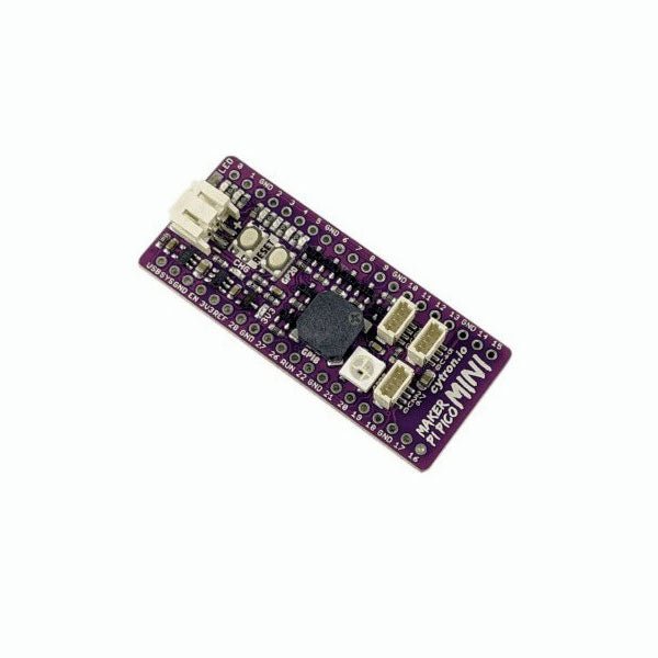
Love the Cytron Maker Pi Pico (SKU 19706) but can't fit it into your project? Now there is the Cytron Maker Pi Pico Mini W. Powered by the awesome Raspberry Pi Pico W, it also inherited most of the useful features from its bigger sibling such as GPIO status LEDs, WS2812B Neopixel RGB LED, passive piezo buzzer, and not forget the user button and reset button. Features Powered by Raspberry Pi Pico W Single-cell LiPo connector with overcharge / over-discharge protection circuit, rechargeable via USB. 6x Status indicator LEDs for GPIOs 1x Passive piezo buzzer (Able to play musical tone or melody) 1x Reset button 1x User programmable button 1x RGB LEDs (WS2812B Neopixel) 3x Maker Ports, compatible with Qwiic, STEMMA QT, and Grove (via conversion cable) Support Arduino IDE, CircuitPython and MicroPython Dimension: 23.12 x 53.85 mm Included 1x Maker Pi Pico Mini W (pre-soldered Raspberry Pi Pico W with preloaded CircuitPython) 3x Grove to JST-SH (Qwiic / STEMMA QT) Cable Downloads Maker Pi Pico Mini Datasheet Maker Pi Pico Mini Schematic Maker Pi Pico Mini Pinout Diagram Official Raspberry Pi Pico Page Getting started with Raspberry Pi Pico CircuitPython for Raspberry Pi Pico Raspberry Pi Pico Datasheet RP2040 Datasheet Raspberry Pi Pico Python SDK Raspberry Pi Pico C/C++ SDK
The Maker pHAT is the solution to the most common problems beginners face starting with Raspberry PI. Its intelligent and simple design makes it easy to attach to your Pi, and it helps you avoid all the tedious work of connection various other accessories. Additionally, the LEDs corresponding to each pin makes it extremely easy to see where a potential problem lies
The Maker pHat has the same size as the Raspberry Pi Zero with all 4mounting holes aligned. However, it can be used with Raspberry Pi 3B, 3B+ and 3A+, by inserting a 2 x 20 stacking header.
Features
Raspberry Pi Zero size, stack perfectly on to Raspberry Pi Zero
Compatible with standard size Raspberry Pi 3B / 3B+, medium size Raspberry Pi 3A+ and smaller size Raspberry Pi Zero / W / WH.
Standard Raspberry Pi GPIO footprint.
LED array for selected GPIO pins (GPIO 17, 18, 27, 22, 25, 12, 13, 19).
3x on board programmable push buttons (GPIO 21, 19 and 20, need to configure as input pull up).
Onboard active buzzer (GPIO 26).
Proper labels for all GPIOs, including SPI, UART, I2C, 5V, 3.3V, and GND.
Utilize USB Micro-B socket for 5V input and USB to UART communication.
USB serial facilitated by the FT231X
Input voltage: USB 5 V, from a computer, power bank or a standard USB adapter.