The software simulation of gauges, control-knobs, meters and indicators which behave just like real hardware components on a PC’s screen is known as virtual instrumentation.
In this book, the Delphi program is used to create these mimics and PIC based external sensors are connected via a USB/RS232 converter communication link to a PC.
Detailed case studies in this Book include a virtual compass displayed on the PC’s screen, a virtual digital storage oscilloscope, virtual -50 to +125 degree C thermometer, and FFT sound analyser, a joystick mouse and many examples detailing virtual instrumentation Delphi components. Arizona’s embedded microcontrollers – the PIC's are used in the projects and include PIC16F84A, PIC16C71, DSPIC30F6012A, PIC16F877, PIC12F629 and the PIC16F887. Much use is made of Microchip’s 44 pin development board (a virtual instrument ‘engine)’, equipped with a PIC16F887 with an onboard potentiometer in conjunction with the PIC’s ADC to simulate the generation of a variable voltage from a sensor/transducer, a UART to enable PC RS232 communications and a bank of 8 LED's to monitor received data is also equipped with an ISP connector to which the ‘PICKIT 2’ programmer may easily be connected.
Full source code examples are provided both for several different PIC’s, both in assembler and C, together with the Pascal code for the Delphi programs which use different 3rd party Delphi virtual components.
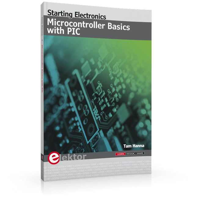
In this book the author presents all essential aspects of microcontroller programming, without overloading the reader with unnecessary or quasi-relevant bits of information. Having read the book, you should be able to understand as well as program, 8-bit microcontrollers.
The introduction to microcontroller programming is worked out using microcontrollers from the PIC series. Not exactly state-of-the-art with just 8 bits, the PIC micro has the advantage of being easy to comprehend. It is offered in a DIP enclosure, widely available and not overly complex. The entire datasheet of the PIC micro is shorter by decades than the description of the architecture outlining the processor section of an advanced microcontroller. Simplicity has its advantages here. Having mastered the fundamental operation of a microcontroller, you can easily enter into the realms of advanced softcores later.
Having placed assembly code as the executive programming language in the foreground in the first part of the book, the author reaches a deeper level with ‘C’ in the second part. Cheerfully alongside the official subject matter, the book presents tips & tricks, interesting measurement technology, practical aspects of microcontroller programming, as well as hands-on options for easier working, debugging and faultfinding.
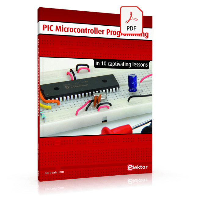
in 10 captivating lessons
Using the lessons in this book you learn how to program a microcontroller. You’ll be using JAL, a free but extremely powerful programming language for PIC microcontrollers, which enjoys great popularity in the hobby world. Starting out from scratch virtually, you slowly build up the knowledge. No previous knowledge is needed: anyone can get started with this book. Assuming you have absorbed all lessons – meaning you have actually completed all the exercises – you should be confident to write PIC microcontroller programs, as well as read and understand programs written by other people.
JAL commands
You learn the function of JAL commands such as include, pin, delay, forever loop, while loop, case, exit loop, repeat until, if then, as well as the use of functions, procedures and timer- and port interrupts.
JAL programs
You make an LED blink, build a time switch, measure a potentiometer’s wiper position, produce sounds, suppress contact bounce, and control the brightness of an LED. And of course you learn to debug, meaning: how to spot and fix errors in your programs.
Hardware
You learn to recognize various components including the PIC microcontroller, potentiometer and quartz crystal, and how to wire up a PIC microcontroller and effectively link it to your PC. A breadboard is used for the purpose, allowing you to easily modify the component arrangement for further experimenting.
The companion software with this book can be downloaded free of charge, including the JAL programming language. In addition, you may order a kit of parts so you don’t have to go shopping for the required components. Especially for a beginner, this is the easiest way to start with this unique pastime.
Having finished this book does not mean you are through with your pastime. You can get your hands dirty again, and if desired use other books packed with fun projects using the JAL programming language. More information may be found at the end of the lessons in the chapter "Done! What’s next?""
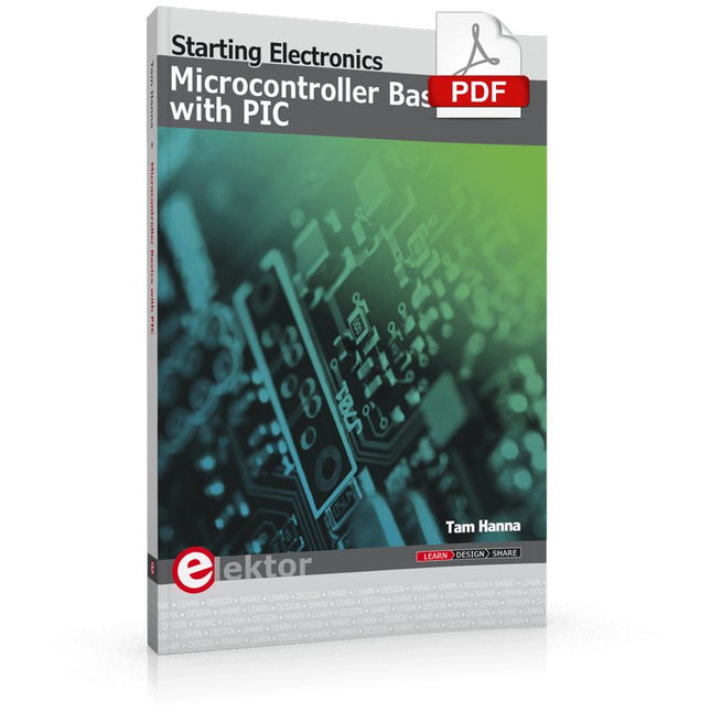
In this book the author presents all essential aspects of microcontroller programming, without overloading the reader with unnecessary or quasi-relevant bits of information. Having read the book, you should be able to understand as well as program, 8-bit microcontrollers.
The introduction to microcontroller programming is worked out using microcontrollers from the PIC series. Not exactly state-of-the-art with just 8 bits, the PIC micro has the advantage of being easy to comprehend. It is offered in a DIP enclosure, widely available and not overly complex. The entire datasheet of the PIC micro is shorter by decades than the description of the architecture outlining the processor section of an advanced microcontroller. Simplicity has its advantages here. Having mastered the fundamental operation of a microcontroller, you can easily enter into the realms of advanced softcores later.
Having placed assembly code as the executive programming language in the foreground in the first part of the book, the author reaches a deeper level with ‘C’ in the second part. Cheerfully alongside the official subject matter, the book presents tips & tricks, interesting measurement technology, practical aspects of microcontroller programming, as well as hands-on options for easier working, debugging and faultfinding.
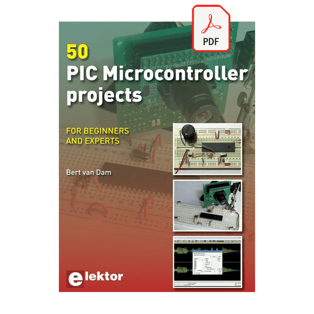
This book contains 50 fun and exciting projects for PIC microcontrollers such as a laser alarm, USB teasing mouse, eggtimer, youth repellent, soundswitch, capacitive liquid level gauge, 'finger in the water' sensor, guarding a room using a camera, mains light dimmer (110-240 volts), talking microcontroller and much more. Several different techniques are discussed such as relay, alternating current control including mains, I²C, SPI, RS232, USB, pulse width modulation, rotary encoder, interrupts, infrared, analog-digital conversion (and the other way around), 7-segment display and even CAN bus.
You can use this book to build the projects for your own use. The clear explanations, schematics and even pictures of each project make this a fun activity. For each project the theory is discussed and why the project has been executed in that particular way. That means you can also use this book as a studybook, or as basis for larger and more complicated projects. All projects use a breadboard so modification and expansion is easy.
Three PIC microcontrollers are used, the 16f877A, 18f4455 and 18f4685. It is also discussed how you can migrate your project from one microcontroller to another – 15 types are supported - including two example projects.
All software that is used in this book can be downloaded for free. That also applies to the open source programming language JAL. This powerful and yet easy to learn language is used by hobbyists as well as professionals.
This book can also be used as a reference guide. It explains all JAL commands, as well as the expansion libraries. Using the index you can easily find example projects that illustrate the use of these commands. Even when you have built all projects in this book you will still want to keep it within arm's reach.
The newcomer to Microchip’s PIC microcontrollers invariably gets an LED to flash as their first attempt to master this technology. You can use just a simple LED indicator in order to show that your initial attempt is working, which will give you confidence to move forward. This is how the book begins — simple programs to flash LEDs, and eventually by stages to use other display indicators such as the 7-segment display, alphanumeric liquid crystal displays and eventually a colour graphic LCD.
As the reader progresses through the book, bigger and upgraded PIC chips are introduced, with full circuit diagrams and source code, both in assembler and C.
In addition, a small tutorial is included using the MPLAB programming environment, together with the EAGLE schematic and PCB design package to enable readers to create their own designs using the book’s many case studies as working examples to work from.
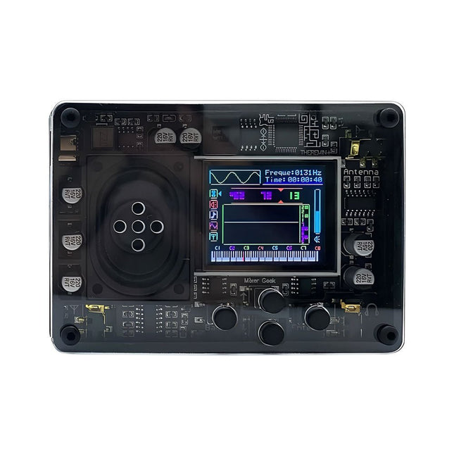
The Mixer Geek Theremin+ is a fun and innovative electronic musical instrument inspired by the classic Theremin. Unlike traditional instruments, the Theremin+ is played without physical contact, using hand movements in the air to control pitch and volume.
The Theremin+ offers an exciting and hands-on way to explore music and sound experimentation.
Features
Ready to use out of the box
Equipped with a loudspeaker and full-color screen
Intuitive button-based navigation and confirmation
Choose from over 70 tones
Multiple customizable function settings
Displays waveform, time, frequency, volume, and corresponding piano pitch (display can be turned off)
Powered via USB-C port; compatible with power banks
Compact design with removable telescopic antenna for easy storage
Connects to headphones, external speakers, or recording devices
Dimensions: 98 x 70 x 18 mm
Included
1x Theremin+ Musical Instrument
2x Antennas
1x USB-C cable
Program and build RPi Pico-based ham station utilities, tools, and instruments
Although much classical HF and mobile equipment is still in use by large numbers of amateurs, the use of computers and digital techniques has now become very popular among amateur radio operators. Nowadays, anyone can purchase a €5 Raspberry Pi Pico microcontroller board and develop many amateur radio projects using the “Pico” and some external components. This book is aimed at amateur radio enthusiasts, Electronic Engineering students, and anyone interested in learning to use the Raspberry Pi Pico to shape their electronic projects. The book is suitable for beginners in electronics as well as for those with wide experience.
Step-by-step installation of the MicroPython programming environment is described. Some knowledge of the Python programming language is helpful to be able to comprehend and modify the projects given in the book. The book introduces the Raspberry Pi Pico and gives examples of many general-purpose, software-only projects that familiarize the reader with the Python programming language. In addition to the software-only projects tailored to the amateur radio operator, Chapter 6 in particular presents over 36 hardware-based projects for “hams”, including:
Station mains power on/off control
Radio station clock
GPS based station geographical coordinates
Radio station temperature and humidity
Various waveform generation methods using software and hardware (DDS)
Frequency counter
Voltmeter / ammeter / ohmmeter / capacitance meter
RF meter and RF attenuators
Morse code exercisers
RadioStation Click board
Raspberry Pi Pico based FM radio
Using Bluetooth and Wi-Fi with Raspberry Pi Pico
Radio station security with RFID
Audio amplifier module with rotary encoder volume control
Morse decoder
Using the FS1000A TX-RX modules to communicate with Arduino
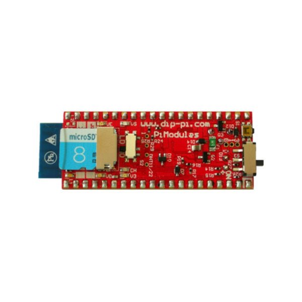
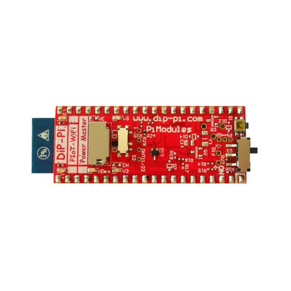
The DiP-Pi PIoT is an Advanced Powered, WiFi connectivity System with sensors embedded interfaces that cover most of possible needs for IoT application based on Raspberry Pi Pico. It can supply the system with up to 1.5 A @ 4.8 V delivered from 6-18 VDC on various powering schemes like Cars, Industrial plant etc., additionally to original micro-USB of the Raspberry Pi Pico. It supports LiPo or Li-Ion Battery with Automatic Charger as also automatic switching from cable powering to battery powering or reverse (UPS functionality) when cable powering lost. Extended Powering Source (EPR) is protected with PPTC Resettable fuse, Reverse Polarity, as also ESD.
The DiP-Pi PIoT contains Raspberry Pi Pico embedded RESET button as also ON/OFF Slide Switch that is acting on all powering sources (USB, EPR or Battery). User can monitor (via Raspberry Pi Pico A/D pins) battery level and EPR Level with PICO’s A/D converters. Both A/D inputs are bridged with 0402 resistors (0 OHM) therefore if for any reason user needs to use those Pico pins for their own application can be easy removed. The charger is automatically charging connected battery (if used) but in addition user can switch charger ON/OFF if their application needs it.
DiP-Pi PIoT can be used for cable powered IoT systems, but also for pure Battery Powered System with ON/OFF. Each powering source status is indicated by separate informative LEDs (VBUS, VSYS, VEPR, CHGR, V3V3).
User can use any capacity of LiPo or Li-Ion type; however, must take care to use PCB protected batteries with max discharge current allowed of 2 A. The embedded battery charger is set to charge battery with 240 mA current. This current is set by resistor so if user need more/less can himself to change it. The DiP-Pi PIoT is also equipped with WiFi ESP8266 Clone module with embedded antenna. This feature open a wide range of IoT applications based on it.
In Addition to all above features DiP-Pi PIoT is equipped with embedded 1-wire, DHT11/22 sensors, and micro–SD Card interfaces. Combination of the extended powering, battery, and sensors interfaces make the DiP-Pi PIoT ideal for IoT applications like data logger, plants monitoring, refrigerators monitoring etc.
DiP-Pi PIoT is supported with plenty of ready to use examples written in Micro Python or C/C++.
Specifications
General
Dimensions 21 x 51 mm
Raspberry Pi Pico pinout compatible
Independent Informative LEDs (VBUS, VSYS, VEPR, CHGR, V3V3)
Raspberry Pi Pico RESET Button
ON/OFF Slide Switch acting on all powering sources (USB, EPR, Battery)
External Powering 6-18 VDC (Cars, Industrial Applications etc.)
External Power (6-18 VDC) Level Monitoring
Battery Level Monitoring
Inverse Polarity Protection
PPTC Fuse Protection
ESD Protection
Automatic Battery Charger (for PCB protected LiPo, Li-Ion – 2 A Max) Automatic/User Control
Automatic Switch from Cable Powering to Battery Powering and reverse (UPS Functionality)
Various powering schemes can be used at the same time with USB Powering, External Powering and Battery Powering
1.5 A @ 4.8 V Buck Converter on EPR
Embedded 3.3 V @ 600 mA LDO
ESP8266 Clone WiFi Connectivity
ESP8266 Firmware Upload Switch
Embedded 1-wire Interface
Embedded DHT-11/22 Interface
Powering Options
Raspberry Pi Pico micro-USB (via VBUS)
External Powering 6-18 V (via dedicated Socket – 3.4/1.3 mm)
External Battery
Supported Battery Types
LiPo with protection PCB max current 2A
Li-Ion with protection PCB max current 2A
Embedded Peripherals and Interfaces
Embedded 1-wire interface
Embedded DHT-11/22 Interface
Micro SD Card Socket
Programmer Interface
Standard Raspberry Pi Pico C/C++
Standard Raspberry Pi Pico Micro Python
Case Compatibility
DiP-Pi Plexi-Cut Case
System Monitoring
Battery Level via Raspberry Pi Pico ADC0 (GP26)
EPR Level via Raspberry Pi Pico ADC1 (GP27)
Informative LEDs
VB (VUSB)
VS (VSYS)
VE (VEPR)
CH (VCHR)
V3 (V3V3)
System Protection
Direct Raspberry Pi Pico Hardware Reset Button
ESD Protection on EPR
Reverse Polarity Protection on EPR
PPTC 500 mA @ 18 V fuse on EPR
EPR/LDO Over Temperature protection
EPR/LDO Over Current protection
System Design
Designed and Simulated with PDA Analyzer with one of the most advanced CAD/CAM Tools – Altium Designer
Industrial Originated
PCB Construction
2 ozcopper PCB manufactured for proper high current supply and cooling
6 mils track/6 mils gap technology 2 layers PCB
PCB Surface Finishing – Immersion Gold
Multi-layer Copper Thermal Pipes for increased System Thermal Response and better passive cooling
Downloads
Datasheet
Manual
The DiP-Pi WiFi Master is an Advanced WiFi connectivity System with sensors embedded interfaces that cover most of possible needs for IoT application based on Raspberry Pi Pico. It is powered directly from the Raspberry Pi Pico VBUS. The DiP-Pi WiFi Master contains Raspberry Pi Pico embedded RESET button as also ON/OFF Slide Switch that is acting on Raspberry Pi Pico Power Sources.
The DiP-Pi WiFi Master is equipped with WiFi ESP8266 Clone module with embedded antenna. This feature open a wide range of IoT applications based on it.
In Addition to all above features DiP-Pi WiFi Master is equipped with embedded 1-wire, DHT11/22 sensors, and micro–SD Card interfaces. Combination of the extended powering, battery, and sensors interfaces make the DiP-Pi WiFi Master ideal for IoT applications like data logger, plants monitoring, refrigerators monitoring etc.
DiP-Pi WiFi Master is supported with plenty of ready to use examples written in Micro Python or C/C++.
Specifications
General
Dimensions 21 x 51 mm
Raspberry Pi Pico pinout compatible
Independent Informative LEDs (VBUS, VSYS, V3V3)
Raspberry Pi Pico RESET Button
ON/OFF Slide Switch acting on Raspberry Pi Pico Powering Source
Embedded 3.3 V @ 600 mA LDO
ESP8266 Clone WiFi Connectivity
ESP8266 Firmware Upload Switch
Embedded 1-wire Interface
Embedded DHT-11/22 Interface
Powering Options
Raspberry Pi Pico micro-USB (via VBUS)
Embedded Peripherals and Interfaces
Embedded 1-wire interface
Embedded DHT-11/22 Interface
Micro SD Card Socket
Programmer Interface
Standard Raspberry Pi Pico C/C++
Standard Raspberry Pi Pico Micro Python
Case Compatibility
DiP-Pi Plexi-Cut Case
Informative LEDs
VB (VUSB)
VS (VSYS)
V3 (V3V3)
System Protection
Direct Raspberry Pi Pico Hardware Reset Button
PPTC 500 mA @ 18 V fuse on EPR
EPR/LDO Over Temperature protection
EPR/LDO Over Current protection
System Design
Designed and Simulated with PDA Analyzer with one of the most advanced CAD/CAM Tools – Altium Designer
Industrial Originated
PCB Construction
2 ozcopper PCB manufactured for proper high current supply and cooling
6 mils track/6 mils gap technology 2 layers PCB
PCB Surface Finishing – Immersion Gold
Multi-layer Copper Thermal Pipes for increased System Thermal Response and better passive cooling
Downloads
Datasheet
Manual
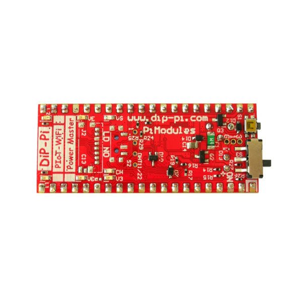
The DiP-Pi Power Master is an Advanced Powering System with embedded sensors interfaces that cover most of possible needs for application based on Raspberry Pi Pico. It can supply the system with up to 1.5 A @ 4.8 V delivered from 6-18 VDC on various powering schemes like Cars, Industrial plant etc., additionally to original micro-USB of the Raspberry Pi Pico. It supports LiPo or Li-Ion Battery with Automatic Charger as also automatic switching from cable powering to battery powering or reverse (UPS functionality) when cable powering lost. Extended Powering Source (EPR) is protected with PPTC Resettable fuse, Reverse Polarity, as also ESD.
The DiP-Pi Power Master contains Raspberry Pi Pico embedded RESET button as also ON/OFF Slide Switch that is acting on all powering sources (USB, EPR or Battery). User can monitor (via Raspberry Pi Pico A/D pins) battery level and EPR Level with PICO’s A/D converters. Both A/D inputs are bridged with 0402 resistors (0 OHM) therefore if for any reason user needs to use those Pico pins for their own application can be easy removed. The charger is automatically charging connected battery (if used) but in addition user can switch charger ON/OFF if their application needs it. DiP-Pi Power Master can be used for cable powered systems, but also for pure Battery Powered System with ON/OFF. Each powering source status is indicated by separate informative LEDs (VBUS, VSYS, VEPR, CHGR, V3V3).
User can use any capacity of LiPo or Li-Ion type; however, must take care to use PCB protected batteries with max discharge current allowed of 2 A. The embedded battery charger is set to charge battery with 240 mA current. This current is set by resistor so if user need more/less can himself to change it.
In Addition to all above features DiP-Pi Power Master is equipped with embedded 1-wire and DHT11/22 sensors interfaces. Combination of the extended powering, battery, and sensors interfaces make the DiP-Pi Power Master ideal for applications like data logger, plants monitoring, refrigerators monitoring etc.
DiP-Pi Power Master is supported with plenty of ready to use examples written in Micro Python or C/C++.
Specifications
General
Dimensions 21 x 51 mm
Raspberry Pi Pico pinout compatible
Independent Informative LEDs (VBUS, VSYS, VEPR, CHGR, V3V3)
Raspberry Pi Pico RESET Button
ON/OFF Slide Switch acting on all powering sources (USB, EPR, Battery)
External Powering 6-18 V DC (Cars, Industrial Applications etc.)
External Power (6-18 VDC) Level Monitoring
Battery Level Monitoring
Inverse Polarity Protection
PPTC Fuse Protection
ESD Protection
Automatic Battery Charger (for PCB protected LiPo, Li-Ion – 2 A Max) Automatic/User Control
Automatic Switch from Cable Powering to Battery Powering and reverse (UPS Functionality)
Various powering schemes can be used at the same time with USB Powering, External Powering and Battery Powering
1.5 A @ 4.8 V Buck Converter on EPR
Embedded 3.3 V @ 600mA LDO
Embedded 1-wire Interface
Embedded DHT-11/22 Interface
Powering Options
Raspberry Pi Pico micro-USB (via VBUS)
External Powering 6-18 V (via dedicated Socket – 3.4/1.3 mm)
External Battery
Supported Battery Types
LiPo with protection PCB max current 2A
Li-Ion with protection PCB max current 2A
Embedded Peripherals and Interfaces
Embedded 1-wire interface
Embedded DHT-11/22 Interface
Programmer Interface
Standard Raspberry Pi Pico C/C++
Standard Raspberry Pi Pico Micro Python
Case Compatibility
DiP-Pi Plexi-Cut Case
System Monitoring
Battery Level via Raspberry Pi Pico ADC0 (GP26)
EPR Level via Raspberry Pi Pico ADC1 (GP27)
Informative LEDs
VB (VUSB)
VS (VSYS)
VE (VEPR)
CH (VCHR)
V3 (V3V3)
System Protection
Direct Raspberry Pi Pico Hardware Reset Button
ESD Protection on EPR
Reverse Polarity Protection on EPR
PPTC 500 mA @ 18 V fuse on EPR
EPR/LDO Over Temperature protection
EPR/LDO Over Current protection
System Design
Designed and Simulated with PDA Analyzer with one of the most advanced CAD/CAM Tools – Altium Designer
Industrial Originated
PCB Construction
2 ozcopper PCB manufactured for proper high current supply and cooling
6 mils track/6 mils gap technology 2 layers PCB
PCB Surface Finishing – Immersion Gold
Multi-layer Copper Thermal Pipes for increased System Thermal Response and better passive cooling
Downloads
Datasheet
Datasheet
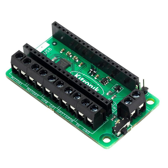
This board allows the Raspberry Pi Pico (connected via pin header) to drive two motors simultaneously with full forward, reverse & stop control, making it ideal for Pico controlled buggy projects. Alternatively, the board can be used to power a stepper motor. The board features the DRV8833 motor driver IC, which has built-in short circuit, over current and thermal protection.
The board has 4 external connections to GPIO pins and a 3 V and GND supply from the Pico. This allows for additional IO options for your buggy builds that can be read or controlled by the Pico. In addition there is an on/off switch and power status LED, allowing you to see at a glance if the board is powered up and save your batteries when your project is not in use.
To use the motor driver board, the Pico should have a soldered pin header and be inserted firmly into the connector. The board produces a regulated supply that is fed into the 40-way connector to power the Pico, removing the need to power the Pico directly. The motor driver board is powered via either screw terminals or a servo style connector.
Kitronik has developed a micro-python module and sample code to support the use of the Motor Driver board with the Pico. This code is available in the GitHub repo.
Features
A compact yet feature-packed board designed to sit at the heart of your Raspberry Pi Pico robot buggy projects.
The board can drive 2 motors simultaneously with full forward, reverse, and stop control.
It features the DRV8833 motor driver IC, which has built-in short circuit, over current and thermal protection.
Additionally, the board features an on/off switch and power status LED.
Power the board via a terminal block style connector.
The 3V and GND pins are also broken out, allowing external devices to be powered.
Code it with MicroPython via an editor such as the Thonny editor.
Dimensions: 63 mm (L) x 35 mm (W) x 11.6 mm (H)
Download
Datasheet