Search results for "peaktech OR 2710 OR digital OR rcd OR tester"
-

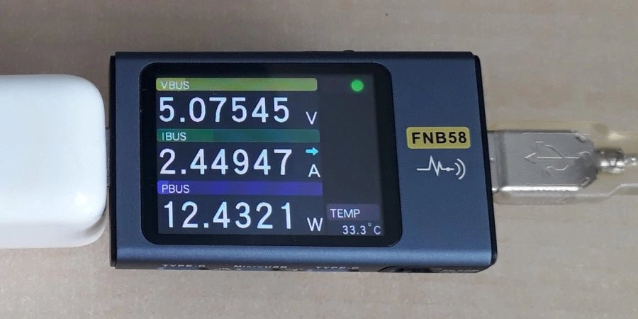
FNIRSI FNIRSI FNB58 USB Tester (with Bluetooth)
The FNIRSI FNB58 USB tester (with Bluetooth) is a comprehensive and very accurate USB voltage and current meter. It features a 2.0-inch full-color HD TFT display, built-in USB-A, micro USB and USB-C interface. With this device you can measure the power supply or power consumption of products or the charging power of cell phones and power supplies. You can also determine the fast charging protocol of chargers. Features USB-A and USB-C interface 2.0" HD display Data at a glance Wide compatibility Ultra-precise data detection Play with fast charging technology Automatic protocol detection (PD2.0, 3.0, 3.1, PPS, QC2.0, 3.0, FCP, SCP, AFC, PE, DASH VOOC, SuperVOOC and more) Simple user interface, easy to operate 4 function curve displays (real-time voltage and current curve, offline curve recording, D+/D- voltage curve, high-speed power supply ripple measurement) Cable detection 10 groups of energy recording battery capacity calculation PC connectivity for data logging and firmware updates Bluetooth app for Android devices Specifications Voltage range 4-28 V Current range 0-7 A Power range 0-120 W Load equivalent internal resistance 0-9999.9 Ω D+/D- voltage 0-3.3 V Capacity 0-9999.99 Ah Power consumption 0-9999.99 Wh Cable resistance 0-9999.9 Ω Interfaces micro USB, USB-A, USB-C Dimensions 42 x 13 x 82 mm Downloads Manual Firmware V0.68
€ 49,95
-
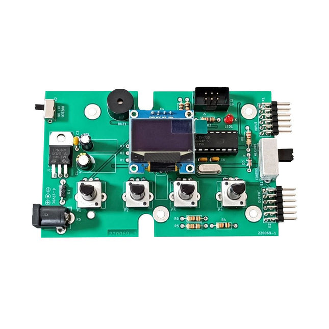
Elektor Labs Elektor Super Servo Tester Kit
The Elektor Super Servo Tester can control servos and measure servo signals. It can test up to four servo channels at the same time. The Super Servo Tester comes as a kit. All the parts required to assemble the Super Servo Tester are included in the kit. Assembling the kit requires basic soldering skills. The microcontroller is already programmed. The Super Servo Tester features two operating modes: Control/Manual and Measure/Inputs. In Control/Manual mode the Super Servo Tester generates control signals on its outputs for up to four servos or for the flight controller or ESC. The signals are controlled by the four potentiometers. In Measure/Inputs the Super Servo Tester measures the servo signals connected to its inputs. These signals may come from for instance an ESC, a flight controller, or the receiver or another device. The signals are also routed to the outputs to control the servos or the flight controller or ESC. The results are shown on the display. Specifications Operating modes Control/Manual & Measure/Inputs Channels 3 Servo signal inputs 4 Servo signal outputs 4 Alarm Buzzer & LED Display 0.96' OLED (128 x 32 pixels) Input voltage on K5 7-12 VDC Input voltage on K1 5-7.5 VDC Input current 30 mA (9 VDC on K5, nothing connected to K1 and K2) Dimensions 113 x 66 x 25 mm Weight 60 g Included Resistors (0.25 W) R1, R3 1 kΩ, 5% R2, R4, R5, R6, R7, R9, R10 10 kΩ, 5% R8 22 Ω, 5% P1, P2, P3, P4 10 kΩ, lin/B, vertical potentiometer Capacitors C1 100 µF 16 V C2 10 µF 25 V C3, C4, C7 100 nF C5, C6 22 pF Semiconductors D1 1N5817 D2 LM385Z-2.5 D3 BZX79-C5V1 IC1 7805 IC2 ATmega328P-PU, programmed LED1 LED, 3 mm, red T1 2N7000 Miscellaneous BUZ1 Piezo buzzer with oscillator K1, K2 2-row, 12-way pinheader, 90° K5 Barrel jack K4 1-row, 4-way pin socket K3 2-row, 6-way boxed pinheader S1 Slide switch DPDT S2 Slide switch SPDT X1 Crystal, 16 MHz 28-way DIP socket for IC2 Elektor PCB OLED display, 0.96', 128 x 32 pixels, 4-pin I²C interface Links Elektor Magazine Elektor Labs
€ 59,95€ 49,95
Members identical
-

Elektor Publishing Digital Electronics
The Basics, New Ideas & Applications Build digital electronics from the ground up—and take it all the way to practical circuits you can use. This book guides you through the core principles of digital technology with a strongly hands-on approach. You’ll begin with the essentials: signals, devices for working with them, and what "logic 0" and "logic 1" mean in real hardware. Simple demonstration setups made from easy-to-find parts (LEDs, diodes, resistors, switches) help you see how logic behaves, making the theory click before you move on. From there, you’ll explore a wide range of logic elements and how they’re implemented, including classic logic families such as TTL and CMOS. The fundamentals section covers the building blocks of digital systems: flip-flops, Schmitt triggers, registers, counters and dividers, encoders/ decoders, multiplexers/demultiplexers, plus A/D and D/A conversion and timing circuits. Next, the book invites you into "new ideas" in digital electronics—universal logic elements, unconventional approaches (including thyristor-based and fractional logic), and creative logic functions that can inspire original designs. Finally, a large, well-organized collection of application circuits turns knowledge into projects: electronic switches and selectors, pulse generators, PWM regulators, frequency multipliers/dividers, phase shifters, and digital filters. Study it deeply, and you’ll gain not only understanding—but the ability to design and debug digital circuits independently.
€ 39,95
Members € 35,96
-
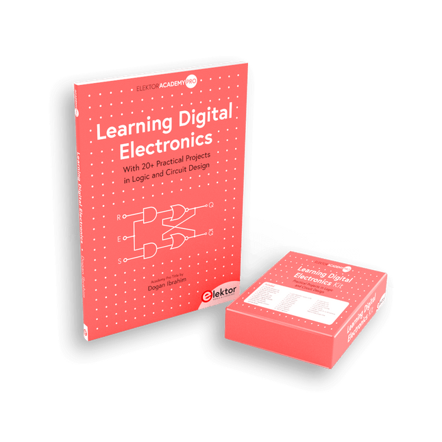
Elektor Bundles Learning Digital Electronics (Bundle)
Master digital electronics – the hands-on way! This bundle includes the book Learning Digital Electronics, featuring 20+ practical projects in Logic and Circuit design, as well as a 100-piece kit – so you can start building logic circuits, counters, displays, and more right away. Learning Digital Electronics (Book) This book is a practical guide to digital electronics, covering the essential components of modern digital systems: number systems, logic gates, Boolean algebra, combinational and sequential logic, and more. Through more than 20 structured projects, you’ll design and build digital systems using real-world components such as logic gates, multiplexers, decoders, flip-flops, counters, and shift registers. The projects range from basic LED logic circuits to digital locks, display systems, traffic light controllers, and timing-based designs. Selected projects introduce the use of tools such as CircuitVerse for circuit simulation, while several designs make use of 74HC-series logic devices, commonly used in digital hardware prototyping. Inside, you’ll find: Clear coverage of number systems and binary arithmetic Logic gate fundamentals and universal gate implementations Step-by-step projects using flip-flops, counters, and registers Real-world design with 74HC-series logic chips Techniques for designing combinational and sequential systems This book takes a design-first, application-driven approach to digital electronics—built around working circuits, tested logic, and hands-on experimentation. Learning Digital Electronics (Kit) This kit has been specially developed to complement the book "Learning Digital Electronics". Since all necessary components are included, you can complete every practical project in the book directly. Kit contents 2x 74HC08 AND gate chip 2x 74HC00 NAND gate chip 1x 74HC86 XOR gate chip 1x 555 timer chip 1x 74HC161 counter chip 1x 74HC164 shift register 1x CD4511 7-segment decoder 1x CD4027 JK flip-flop 1x BC337 NPN transistor 1x KPS-5161 7-segment common-cathode display 1x Light dependent resistor (LDR) 4x 10 KΩ resistors 8x 1 KΩ resistor 2x 47 KΩ resistors 1x 100 KΩ resistor 4x 2.7 KΩ resistors 1x 5.6 KΩ resistor 1x 150 KΩ resistor 1x 10 μF capacitor 2x 0.01 μF capacitor 2x 100 nF capacitor 8x Small red LED 1x Small green LED 1x Small orange LED 4x Pushbutton switches 1x Active buzzer 1x Battery holder for 3x AA batteries (batteries not included) 1x Breadboard 40x Male-to-male jumper wires (length: 200 mm)
€ 69,95€ 59,95
Members identical
-

Elektor Publishing Learning Digital Electronics
With 20+ Practical Projects in Logic and Circuit Design This book is a practical guide to digital electronics, covering the essential components of modern digital systems: number systems, logic gates, Boolean algebra, combinational and sequential logic, and more. Through more than 20 structured projects, you’ll design and build digital systems using real-world components such as logic gates, multiplexers, decoders, flip-flops, counters, and shift registers. The projects range from basic LED logic circuits to digital locks, display systems, traffic light controllers, and timing-based designs. Selected projects introduce the use of tools such as CircuitVerse for circuit simulation, while several designs make use of 74HC-series logic devices, commonly used in digital hardware prototyping. Inside, you’ll find: Clear coverage of number systems and binary arithmetic Logic gate fundamentals and universal gate implementations Step-by-step projects using flip-flops, counters, and registers Real-world design with 74HC-series logic chips Techniques for designing combinational and sequential systems This book takes a design-first, application-driven approach to digital electronics—built around working circuits, tested logic, and hands-on experimentation.
€ 29,95
Members € 26,96
-

Elektor Digital Digital Electronics (E-book)
The Basics, New Ideas & Applications Build digital electronics from the ground up—and take it all the way to practical circuits you can use. This book guides you through the core principles of digital technology with a strongly hands-on approach. You’ll begin with the essentials: signals, devices for working with them, and what "logic 0" and "logic 1" mean in real hardware. Simple demonstration setups made from easy-to-find parts (LEDs, diodes, resistors, switches) help you see how logic behaves, making the theory click before you move on. From there, you’ll explore a wide range of logic elements and how they’re implemented, including classic logic families such as TTL and CMOS. The fundamentals section covers the building blocks of digital systems: flip-flops, Schmitt triggers, registers, counters and dividers, encoders/ decoders, multiplexers/demultiplexers, plus A/D and D/A conversion and timing circuits. Next, the book invites you into "new ideas" in digital electronics—universal logic elements, unconventional approaches (including thyristor-based and fractional logic), and creative logic functions that can inspire original designs. Finally, a large, well-organized collection of application circuits turns knowledge into projects: electronic switches and selectors, pulse generators, PWM regulators, frequency multipliers/dividers, phase shifters, and digital filters. Study it deeply, and you’ll gain not only understanding—but the ability to design and debug digital circuits independently.
€ 32,95
Members € 26,36
-

Elektor Digital Learning Digital Electronics (E-book)
With 20+ Practical Projects in Logic and Circuit Design This book is a practical guide to digital electronics, covering the essential components of modern digital systems: number systems, logic gates, Boolean algebra, combinational and sequential logic, and more. Through more than 20 structured projects, you’ll design and build digital systems using real-world components such as logic gates, multiplexers, decoders, flip-flops, counters, and shift registers. The projects range from basic LED logic circuits to digital locks, display systems, traffic light controllers, and timing-based designs. Selected projects introduce the use of tools such as CircuitVerse for circuit simulation, while several designs make use of 74HC-series logic devices, commonly used in digital hardware prototyping. Inside, you’ll find: Clear coverage of number systems and binary arithmetic Logic gate fundamentals and universal gate implementations Step-by-step projects using flip-flops, counters, and registers Real-world design with 74HC-series logic chips Techniques for designing combinational and sequential systems This book takes a design-first, application-driven approach to digital electronics—built around working circuits, tested logic, and hands-on experimentation.
€ 24,95
Members € 19,96
-
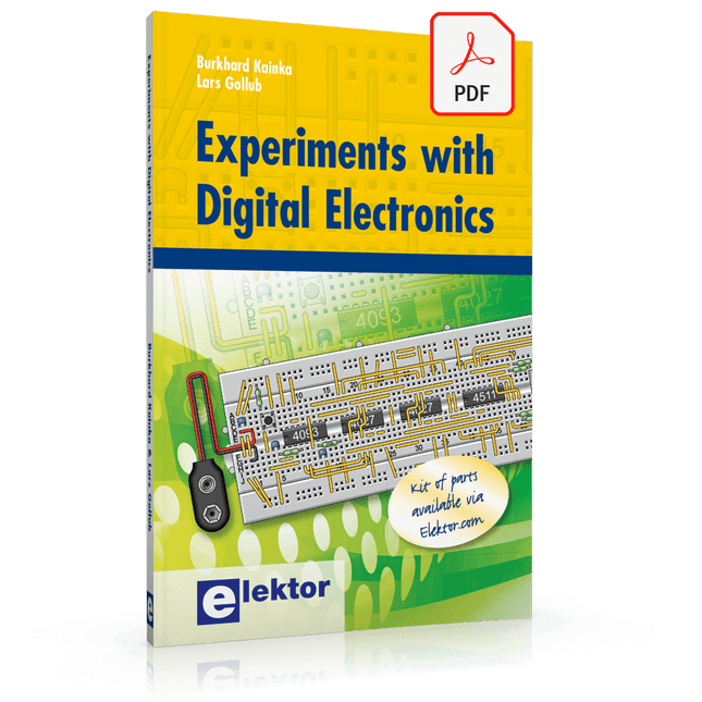
Elektor Digital Experiments with Digital Electronics (E-book)
The field of digital electronics is central to modern technology. This e-book presents fundamental circuits using gates, flip-flops and counters from the CMOS 4000 Series. Each of the 50 experiments has a circuit diagram as well as a detailed illustration of the circuit’s construction on solderless breadboard. Learning these fundamentals is best done using practical experiments. Building these digital circuits will improve your knowledge and will be fun to boot. Many of the circuits presented here have practical real-life applications. With a good overview of the field, you’ll be well equipped to find simple and cost-effective solutions for any application. The e-book is targeted essentially at students, trainees and anyone with an interest in and requiring an introduction to digital control electronics. Moreover, the knowledge gleaned here is the foundation for further projects in the field of microcontrollers and programming.
€ 24,95
Members € 19,96
-
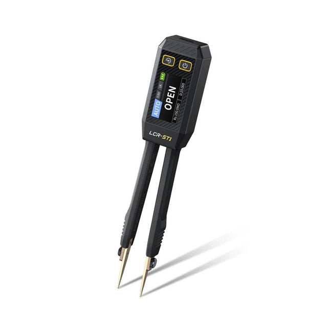
FNIRSI FNIRSI LCR-ST1 Smart SMD Tweezers (LCR/ESR Tester)
The FNIRSI LCR-ST1 is a compact, multifunctional, and smart LCR tester that supports automatic measurements of resistance, capacitance, inductance, diode testing, and continuity. Its 1.14-inch color display combined with a convenient magnetic adsorption function enhances ease of use, while the built-in 250 mAh lithium battery ensures long-lasting performance. The device supports three frequency ranges (100 Hz, 1 kHz and 10 kHz) and offers 0.3 V and 0.6 V RMS test levels for versatile testing applications. The unique tweezer-shaped design of the LCR-ST1 is ideal for delicate tasks in confined spaces and enables fast and accurate testing of electronic components. Its light weight and portable design make it an invaluable tool for both field and laboratory use. Whether you are an experienced engineer or just starting out in electronics, the LCR-ST1 delivers reliable and accurate measurement results, allowing you to complete your tasks with greater efficiency and precision. Features Offers 3 test frequencies (100 Hz, 1 kHz, 10 kHz) and 2 test voltage levels. Features automatic component identification for faster and more reliable measurements. High-resolution 1.14-inch color display for clear readouts. Supports automatic data recording and storage. The tweezer tips are made from gold-plated brass for enhanced durability and conductivity. Specifications Resistance Range 10 mΩ – 10 MΩ Capacitance Range 1 pF – 22 mF Inductance Range 1 μh – 10 H Diode On voltage 0.7 V Frequency Test 100 Hz, 1k Hz, 10 KHz Level Test 0.3 V, 0.6 V RMS Parameter Display ESR, D value, Q value, Z value, X value Display 1.14" HD color screen Charging Interface USB-C, 5 V/1 A Power Supply Built-in 250 mAh lithium battery Auto Recognition Measurement Yes Replaceable Tweezer Head Yes Auto Shutdown Yes Data Hold Yes History Record Connect to PC to view and export Dimensions 28 x 19 x 150 mm Weight 41 g Included 1x LCR-ST1 SMD Tweezers 2x Hook Tips 1x Magnetic Patch 1x USB cable 1x Tool bag 1x Manual Downloads Manual Firmware V1.6
€ 34,95
-
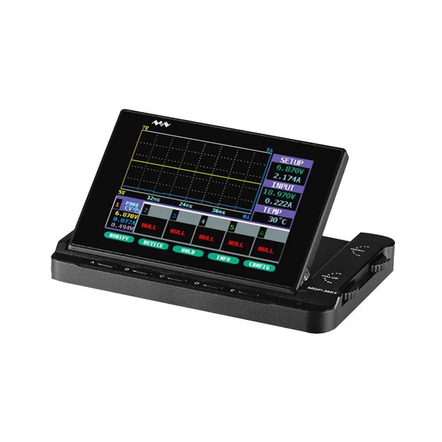
Miniware Miniware MDP-M01 Smart Digital Monitor
MDP-M01 is a display control module equipped with a 2.8-inch TFT display screen, the screen can be turned 90 degrees, which is convenient for users to view data and waveform. MDP-M01 can realize online display and control with MDP-P906 mini digital power supply modules and other modules of MDP system through 2.4 GHz wireless communication, and can control up to 6 sub-modules at the same time. Specifications Screen size 2.8" TFT Screen resolution 240 x 320 Power Micro USB power input, or taking power from sub-module via dedicated power cable Input DC 5 V/0.3 A Other functions Can control up to 6 sub-modulesUpgrade firmware through Micro USB Dimensions 107 x 66 x 13.6 mm Weight 133 g Included 1x MDP-M01 Smart Digital Monitor 1x Cable (2.5 mm jack to Micro USB) Downloads User Manual v3.4 Firmware v1.32
€ 79,00
-
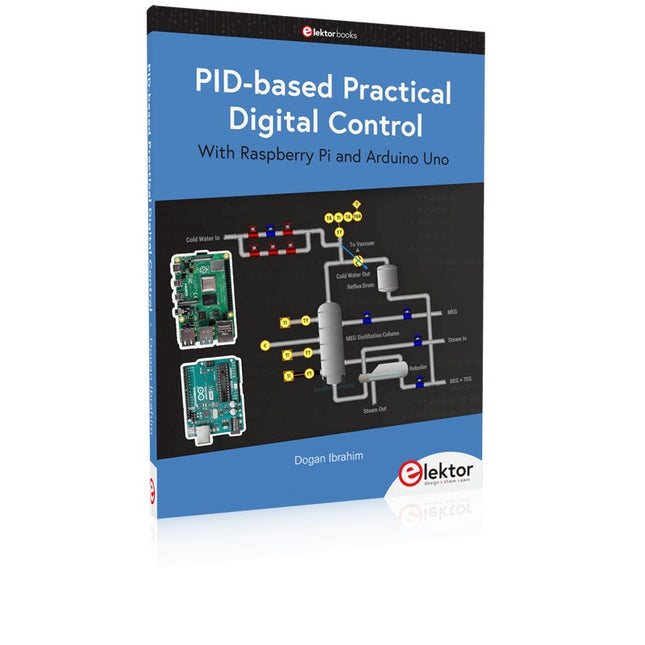
Elektor Publishing PID-based Practical Digital Control with Raspberry Pi and Arduino Uno
The Arduino Uno is an open-source microcontroller development system encompassing hardware, an Integrated Development Environment (IDE), and a vast number of libraries. It is supported by an enormous community of programmers, electronic engineers, enthusiasts, and academics. The libraries in particular really smooth Arduino programming and reduce programming time. What’s more, the libraries greatly facilitate testing your programs since most come fully tested and working. The Raspberry Pi 4 can be used in many applications such as audio and video media devices. It also works in industrial controllers, robotics, games, and in many domestic and commercial applications. The Raspberry Pi 4 also offers Wi-Fi and Bluetooth capability which makes it great for remote and Internet-based control and monitoring applications. This book is about using both the Raspberry Pi 4 and the Arduino Uno in PID-based automatic control applications. The book starts with basic theory of the control systems and feedback control. Working and tested projects are given for controlling real-life systems using PID controllers. The open-loop step time response, tuning the PID parameters, and the closed-loop time response of the developed systems are discussed together with the block diagrams, circuit diagrams, PID controller algorithms, and the full program listings for both the Raspberry Pi and the Arduino Uno. The projects given in the book aim to teach the theory and applications of PID controllers and can be modified easily as desired for other applications. The projects given for the Raspberry Pi 4 should work with all other models of Raspberry Pi family. The book covers the following topics: Open-loop and closed-loop control systems Analog and digital sensors Transfer functions and continuous-time systems First-order and second-order system time responses Discrete-time digital systems Continuous-time PID controllers Discrete-time PID controllers ON-OFF temperature control with Raspberry Pi and Arduino Uno PID-based temperature control with Raspberry Pi and Arduino Uno PID-based DC motor control with Raspberry Pi and Arduino Uno PID-based water level control with Raspberry Pi and Arduino Uno PID-based LED-LDR brightness control with Raspberry Pi and Arduino Uno
€ 39,95
Members € 35,96


-
, by Jean-François Simon Fnirsi FNB58 USB Tester (Review)
The Fnirsi FNB58 is a versatile USB tester capable of performing a wide array of voltage, current, and energy measurements, as well as supporting numerous...
