This bundle contains:
Book: Get Started with the NXP FRDM-MCXN947 Development Board (normal price: €40)
NXP FRDM-MCXN947 Development Board (normal price: €30)
Book: Get Started with the NXP FRDM-MCXN947 Development Board
Develop projects on connectivity, graphics, machine learning, motor control, and sensors
This book is about the use of the FRDM-MCXN947 Development Board, developed by NXP Semiconductors. It integrates the dual Arm Cortex-M33, operating at up to 150 MHz. Ideal for Industrial, IoT, and machine learning applications. It features Hi-Speed USB, CAN 2.0, I³C and 10/100 Ethernet. The board includes an on-board MCU-Link debugger, FlexI/O for LCD control, and dual-bank flash for read-while-write operations, supporting large external serial memory configurations.
One of the important features of the development board is that it features an integrated eIQ Neutron Neural Processing Unit (NPU), thus enabling users to develop AI-based projects. The development board also supports Arduino Uno form factor header pins, making it compatible with many Arduino shields, mikroBUS connector for MikroElektronika Click Boards, and Pmod connector.
One of the nice things of the FRDM-MCXN947 development board is that it includes several on-board debug probes, allowing programmers to debug their programs by communicating directly with the MCU. With the help of the debugger, programmers can single-step through a program, insert breakpoints, view and modify variables and so on.
Many working and tested projects have been developed in the book using the popular MCUXpresso IDE and the SDK with various sensors and actuators. Use of the popular CMSIS-DSP library is also explained with several commonly used matrix operations.
The projects provided in the book can be used without any modifications in many applications. Alternatively, readers can base their projects on those given in the book during the development of their own projects.
NXP FRDM-MCXN947 Development Board
The FRDM-MCXN947 is a compact and versatile development board designed for rapid prototyping with MCX N94 and N54 microcontrollers. It features industry-standard headers for easy access to the MCU's I/Os, integrated open-standard serial interfaces, external flash memory, and an onboard MCU-Link debugger.
Specifications
Microcontroller
MCX-N947 Dual Arm Cortex-M33 cores @ 150 MHz each with optimized performance efficiency, up to 2 MB dual-bank flash with optional full ECC RAM, External flash
Accelerators: Neural Processing Unit, PowerQuad, Smart DMA, etc.
Memory Expansion
*DNP Micro SD card socket
Connectivity
Ethernet Phy and connector
HS USB-C connectors
SPI/I²C/UART connector (PMOD/mikroBUS, DNP)
WiFi connector (PMOD/mikroBUS, DNP)
CAN-FD transceiver
Debug
On-board MCU-Link debugger with CMSIS-DAP
JTAG/SWD connector
Sensor
P3T1755 I³C/I²C Temp Sensor, Touch Pad
Expansion Options
Arduino Header (with FRDM expansion rows)
FRDM Header
FlexIO/LCD Header
SmartDMA/Camera Header
Pmod *DNP
mikroBUS
User Interface
RGB user LED, plus Reset, ISP, Wakeup buttons
Included
1x FRDM-MCXN947 Development Board
1x USB-C Cable
1x Quick Start Guide
Downloads
Datasheet
Block diagram
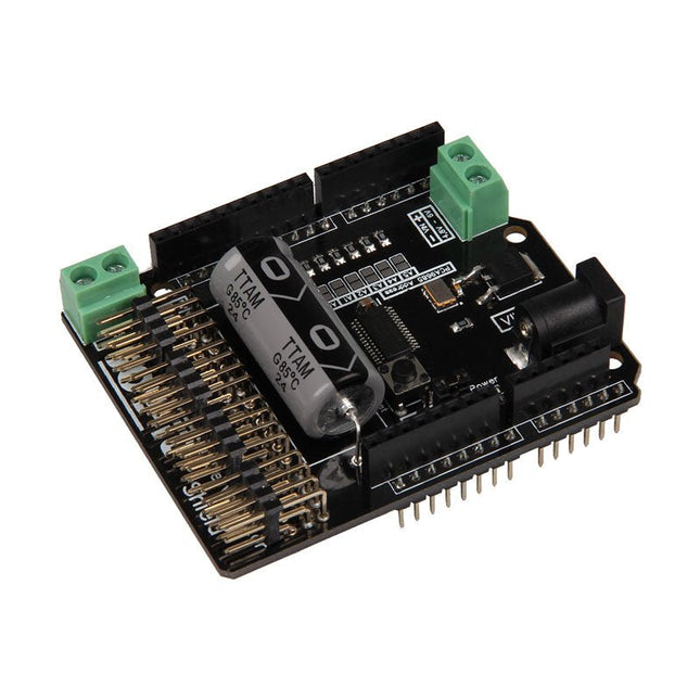
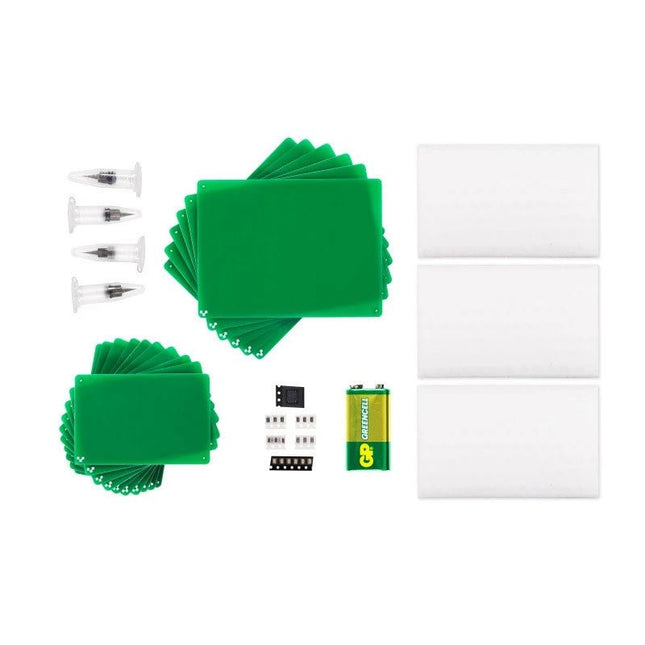
The Motorino board is an extension-board to control and use up to 16 PWM-controlled 5V-Servo-motors.
The included clock generator ensures a very precise PWM signal and a very precise positioning.
The board has 2 inputs for voltage from 4.8 V to 6 V which can be used for up to 11 A. With this input, a perfect power supply is always guaranteed and even bigger projects are no problem.
The supply runs directly over the Motorino which provides a connection for voltage, ground and control.
With the build in capacitor, the voltage is buffered which prevents a sudden voltage-drop at a high load. But there is also the possibility to connect another capacitor.
The control and the programing can be done, as usual, with the Arduino. Manuals and code examples allows a quick introduction for beginners.
Specifications
Special features
16 Channels, own clock generator
Input 1
Coaxial power connector 5.5 / 2.1 mm, 4.8-6 V / 5 A max
Input 2
Screw-terminal, 4.8-6 V / 6 A max
Communication
16 x PWM
Compatible with
Arduino Uno, Mega and may more microcontroller with Arduino compatible pinout
Dimensions
69 x 24 x 56 mm
Included
Board, Manual, Retail package
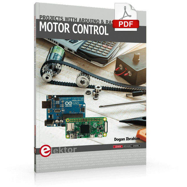
This book is about DC electric motors and their use in Arduino and Raspberry Pi Zero W based projects. The book includes many tested and working projects where each project has the following sub-headings:
Title of the project
Description of the project
Block diagram
Circuit diagram
Project assembly
Complete program listing of the project
Full description of the program
The projects in the book cover the standard DC motors, stepper motors, servo motors, and mobile robots. The book is aimed at students, hobbyists, and anyone else interested in developing microcontroller based projects using the Arduino Uno or the Raspberry Pi Zero W.
One of the nice features of this book is that it gives complete projects for remote control of a mobile robot from a mobile phone, using the Arduino Uno as well as the Raspberry Pi Zero W development boards. These projects are developed using Wi-Fi as well as the Bluetooth connectivity with the mobile phone. Readers should be able to move a robot forward, reverse, turn left, or turn right by sending simple commands from a mobile phone. Full program listings of all the projects as well as the detailed program descriptions are given in the book. Users should be able to use the projects as they are presented, or modify them to suit to their own needs.
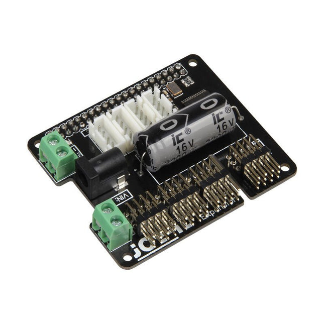
The MotoPi is an extension-board to control and use up to 16 PWM-controlled 5 V servo motors. The board can be additional powered by a voltage between 4.8 V and 6 V so a perfect supply is always guaranteed and even larger projects can be powered.
With the additional power supply and the integrated Analog-Digital-Converter, new possibilities can be reached. An additional power supply per motor is not required anymore because all connections (Voltage, Ground, Control) are directly connected to the board.
The control and the programing can be directly done, as usual, on the Raspberry Pi.
Specifications
Special features
16 Channels, own clock generator, Inkl. Analog Digital Converter
Input 1
Coaxial power connector 5.5 / 2.1 mm, 5 V / 6 A max
Input 2
Screw terminal, 4.8-6 V / 6 A max
Compatible with
Raspberry Pi A+, B+, 2B, 3B
Dimensions
65 x 56 x 24 mm
Scope of supply
Board, manual, fixing material
The LuckFox Pico Ultra is a compact single-board computer (SBC) powered by the Rockchip RV1106G3 chipset, designed for AI processing, multimedia, and low-power embedded applications.
It comes equipped with a built-in 1 TOPS NPU, making it ideal for edge AI workloads. With 256 MB RAM, 8 GB onboard eMMC storage, integrated WiFi, and support for the LuckFox PoE module, the board delivers both performance and versatility across a wide range of use cases.
Running Linux, the LuckFox Pico Ultra supports a variety of interfaces – including MIPI CSI, RGB LCD, GPIO, UART, SPI, I²C, and USB – providing a simple and efficient development platform for applications in smart home, industrial control, and IoT.
Specifications
Chip
Rockchip RV1106G3
Processor
Cortex-A7 1.2 GHz
Neural Network Processor (NPU)
1 TOPS, supports int4, int8, int16
Image Processor (ISP)
Max input 5M @30fps
Memory
256 MB DDR3L
WiFi + Bluetooth
2.4GHz WiFi-6 Bluetooth 5.2/BLE
Camera Interface
MIPI CSI 2-lane
DPI Interface
RGB666
PoE Interface
IEEE 802.3af PoE
Speaker interface
MX1.25 mm
USB
USB 2.0 Host/Device
GPIO
30 GPIO pins
Ethernet
10/100M Ethernet controller and embedded PHY
Default Storage Medium
eMMC (8 GB)
Included
1x LuckFox Pico Ultra W
1x LuckFox PoE module
1x IPX 2.4G 2 db antenna
1x USB-A to USB-C cable
1x Screws pack
Downloads
Wiki
The ATmega328 Uno Development Board (Arduino Uno compatible) is a microcontroller board based on the ATmega328.
It has 14 digital input/output pins (of which 6 can be used as PWM outputs), 6 analogue inputs, a 16 MHz ceramic resonator, a USB connection, a power jack, an ICSP header and a reset button.
It contains everything needed to support the microcontroller; connect it to a computer with a USB cable or power it with a AC-to-DC adapter or battery to get started.
Specifications
Microcontroller
ATmega328
Operating voltage
5 V DC
Input voltage (recommended)
7-12 V DC
Input voltage (limits)
6-20 V DC
Digital I/O pins
14 (of which 6 provide PWM output)
Analogue input pins
6
SRAM
2 kB (ATmega328)
EEPROM
1 kB (ATmega328)
Flash memory
32 kB (ATmega328) of which 0.5 kB used by bootloader
Clock speed
16 MHz
Downloads
Manual
The FRDM-MCXN947 is a compact and versatile development board designed for rapid prototyping with MCX N94 and N54 microcontrollers. It features industry-standard headers for easy access to the MCU's I/Os, integrated open-standard serial interfaces, external flash memory, and an onboard MCU-Link debugger.
Specifications
Microcontroller
MCX-N947 Dual Arm Cortex-M33 cores @ 150 MHz each with optimized performance efficiency, up to 2 MB dual-bank flash with optional full ECC RAM, External flash
Accelerators: Neural Processing Unit, PowerQuad, Smart DMA, etc.
Memory Expansion
*DNP Micro SD card socket
Connectivity
Ethernet Phy and connector
HS USB-C connectors
SPI/I²C/UART connector (PMOD/mikroBUS, DNP)
WiFi connector (PMOD/mikroBUS, DNP)
CAN-FD transceiver
Debug
On-board MCU-Link debugger with CMSIS-DAP
JTAG/SWD connector
Sensor
P3T1755 I³C/I²C Temp Sensor, Touch Pad
Expansion Options
Arduino Header (with FRDM expansion rows)
FRDM Header
FlexIO/LCD Header
SmartDMA/Camera Header
Pmod *DNP
mikroBUS
User Interface
RGB user LED, plus Reset, ISP, Wakeup buttons
Included
1x FRDM-MCXN947 Development Board
1x USB-C Cable
1x Quick Start Guide
Downloads
Datasheet
Block diagram
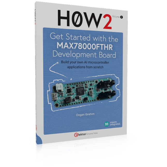
Build your own AI microcontroller applications from scratch
The MAX78000FTHR from Maxim Integrated is a small development board based on the MAX78000 MCU. The main usage of this board is in artificial intelligence applications (AI) which generally require large amounts of processing power and memory. It marries an Arm Cortex-M4 processor with a floating-point unit (FPU), convolutional neural network (CNN) accelerator, and RISC-V core into a single device. It is designed for ultra-low power consumption, making it ideal for many portable AI-based applications.
This book is project-based and aims to teach the basic features of the MAX78000FTHR. It demonstrates how it can be used in various classical and AI-based projects. Each project is described in detail and complete program listings are provided. Readers should be able to use the projects as they are, or modify them to suit their applications. This book covers the following features of the MAX78000FTHR microcontroller development board:
Onboard LEDs and buttons
External LEDs and buttons
Using analog-to-digital converters
I²C projects
SPI projects
UART projects
External interrupts and timer interrupts
Using the onboard microphone
Using the onboard camera
Convolutional Neural Network
The OKdo E1 is an ultra-low-cost Development Board based on the NXP LPC55S69JBD100 dual-core Arm Cortex-M33 microcontroller. The E1 board is perfect for Industrial IoT, building control and automation, consumer electronics, general embedded and secure applications.
Features
Processor with Arm TrustZone, Floating Point Unit (FPU) and Memory Protection Unit (MPU)
CASPER Crypto co-processor to enable hardware acceleration for certain asymmetric cryptographic algorithms
PowerQuad Hardware Accelerator for fixed and floating point DSP functions
SRAM Physical Unclonable Function (PUF) for key generation, storage and reconstruction
PRINCE module for real-time encryption and decryption of flash data
AES-256 and SHA2 engines
Up to Nine Flexcomm interfaces. Each Flexcomm interface can be selected by software to be a USART, SPI, I²C, and I²S interface
USB 2.0 High-Speed Host/Device controller with on-chip PHY
USB 2.0 Full-Speed Host/Device controller with on-chip PHY
Up to 64 GPIOs
Secure digital input/output (SD/MMC and SDIO) card interface
Specifications
LPC55S69JBD100 640kbyte flash microcontroller
In-built CMSIS-DAP v1.0.7 debugger based on LPC11U35
Internal PLL support up to 100MHz operation, 16MHz can be mounted for full 150MHz operation.
SRAM 320kB
32kHz crystal for real-time clock
4 user switches
3-colour LED
User USB connector
2-off 16-way expansion connectors
UART over USB virtual COM port
The EC200U-EU C4-P01 development board features the EC200U-EU LTE Cat 1 wireless communication module, offering a maximum data rate of up to 10 Mbps for downlink and 5 Mbps for uplink. It supports multi-mode and multi-band communication, making it a cost-effective solution.
The board is designed in a compact and unified form factor, compatible with the Quectel multi-mode LTE Standard EC20-CE. It includes an onboard USB-C port, allowing for easy development with just a USB-C cable.
Additionally, the board is equipped with a 40-pin GPIO header that is compatible with most Raspberry Pi HATs.
Features
Equipped with EC200U-EU LTE Cat 1 wireless communication module, multi-mode & multi-band support
Onboard 40-Pin GPIO header, compatible with most Raspberry Pi HATs
5 LEDs for indicating module operating status
Supports TCP, UDP, PPP, NITZ, PING, FILE, MQTT, NTP, HTTP, HTTPS, SSL, FTP, FTPS, CMUX, MMS protocols, etc.
Supports GNSS positioning (GPS, GLONASS, BDS, Galileo, QZSS)
Onboard Nano SIM card slot and eSIM card slot, dual card single standby
Onboard MIPI connector for connecting MIPI screen and is fully compatible with Raspberry Pi peripherals
Onboard camera connector, supports customized SPI cameras with a maximum of 300,000 pixels
Provides tools such as QPYcom, Thonny IDE plugin, and VSCode plugin, etc. for easy learning and development
Comes with online development resources and manual (example in QuecPython)
Specifications
Applicable Regions
Europe, Middle East, Africa, Australia, New Zealand, Brazil
LTE-FDD
B1, B3, B5, B7, B8, B20, B28
LTE-TDD
B38, B40, B41
GSM / GPRS / EDGE
GSM: B2, B3, B5, B8
GNSS
GPS, GLONASS, BDS, Galileo, QZSS
Bluetooth
Bluetooth 4.2 (BR/EDR)
Wi-Fi Scan
2.4 GHz 11b (Rx)
CAT 1
LTE-FDD: DL 10 Mbps; UL 5 Mbps
LTE-TDD: DL 8.96 Mbps; UL 3.1 Mbps
GSM / GPRS / EDGE
GSM: DL 85.6 Kbps; UL 85.6 Kbps
USB-C Port
Supports AT commands testing, GNSS positioning, firmware upgrading, etc.
Communication Protocol
TCP, UDP, PPP, NITZ, PING, FILE, MQTT, NTP, HTTP, HTTPS, SSL, FTP, FTPS, CMUX, MMS
SIM Card
Nano SIM and eSIM, dual card single standby
Indicator
P01: Module Pin 1, default as EC200A-XX PWM0
P05: Module Pin 5, NET_MODE indicator
SCK1: SIM1 detection indicator, lights up when SIM1 card is inserted
SCK2: SIM2 detection indicator, lights up when SIM2 card is inserted
PWR: Power indicator
Buttons
PWK: Power ON/OFF
RST: Reset
BOOT: Forcing into firmware burning mode
USB ON/OFF: USB power consumption detection switch
Antenna Connectors
LTE main antenna + DIV / WiFi (scanning only) / Bluetooth antenna + GNSS antenna
Operating Temperature
−30~+75°C
Storage Temperature
−45~+90°C
Downloads
Wiki
Quectel Resources