Search results for "motor OR control OR development OR bundle"
-
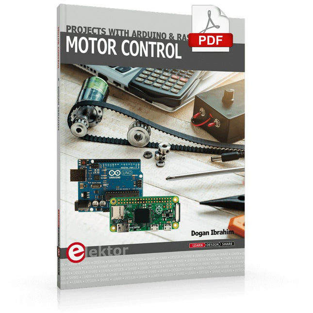
Elektor Digital Motor Control - Projects with Arduino & Raspberry Pi (E-book)
This book is about DC electric motors and their use in Arduino and Raspberry Pi Zero W based projects. The book includes many tested and working projects where each project has the following sub-headings: Title of the project Description of the project Block diagram Circuit diagram Project assembly Complete program listing of the project Full description of the program The projects in the book cover the standard DC motors, stepper motors, servo motors, and mobile robots. The book is aimed at students, hobbyists, and anyone else interested in developing microcontroller based projects using the Arduino Uno or the Raspberry Pi Zero W. One of the nice features of this book is that it gives complete projects for remote control of a mobile robot from a mobile phone, using the Arduino Uno as well as the Raspberry Pi Zero W development boards. These projects are developed using Wi-Fi as well as the Bluetooth connectivity with the mobile phone. Readers should be able to move a robot forward, reverse, turn left, or turn right by sending simple commands from a mobile phone. Full program listings of all the projects as well as the detailed program descriptions are given in the book. Users should be able to use the projects as they are presented, or modify them to suit to their own needs.
€ 29,95
Members: € 23,96
-

€ 77,75€ 54,95
Best Price
-

€ 84,75€ 64,95
Best Price
-

€ 84,90€ 69,95
Best Price
-

€ 79,90€ 59,95
Best Price
-

€ 122,90€ 99,95
Best Price
-

€ 69,90€ 49,95
Best Price
-

€ 99,90€ 79,95
Best Price
-
€ 84,90€ 64,95
Best Price
-

€ 253,95€ 229,00
Best Price
-
€ 92,90€ 69,95
Best Price
-
€ 199,90€ 179,95
Best Price


