Search results for "mikrocontroller OR praxiskurs OR fur OR arduino OR fortgeschrittene"
-
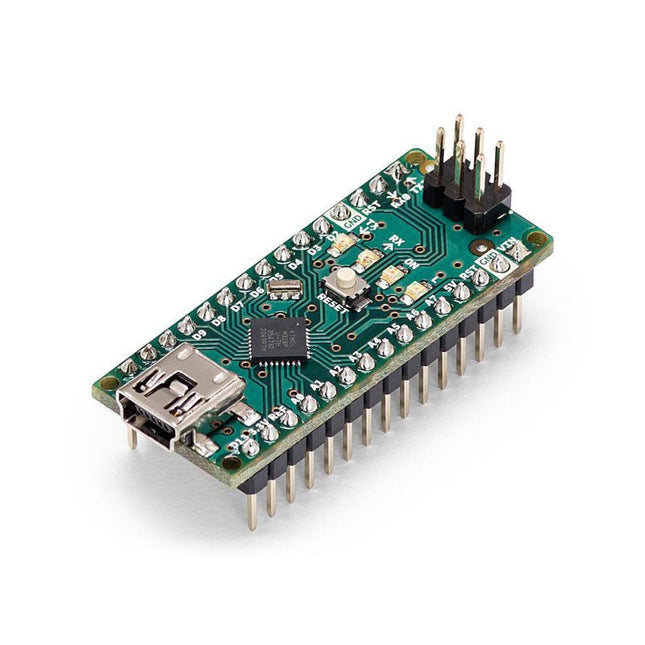
Arduino Arduino Nano
The Arduino Nano is a small, complete, and breadboard-friendly board based on the ATmega328 (Arduino Nano 3.x). It has more or less the same functionality of the Arduino Duemilanove but in a different package. It lacks only a DC power jack and works with a Mini-B USB cable instead of a standard one. Specifications Microcontroller ATmega328 Operating Voltage (logic level) 5 V Input Voltage (recommended) 7-12 V Input Voltage (limits) 6-20 V Digital I/O Pins 14 (of which 6 provide PWM output) Analog Input Pins 8 DC Current per I/O Pin 40 mA Flash Memory 16 KB (ATmega168) or 32 KB (ATmega328) of which 2 KB used by bootloader SRAM 1 KB (ATmega168) or 2 KB (ATmega328) EEPROM 512 bytes (ATmega168) or 1 KB (ATmega328) Clock Speed 16 MHz Dimensions 0.73 x 1.70' (18 x 45 mm) Power The Arduino Nano can be powered via the Mini-B USB connection, 6-20 V unregulated external power supply (pin 30), or 5 V regulated external power supply (pin 27). The power source is automatically selected to the highest voltage source. Memory The ATmega168 has 16 KB of flash memory for storing code (of which 2 KB is used for the bootloader), 1 KB of SRAM and 512 bytes of EEPROM The ATmega328 has 32 KB of flash memory for storing code, (also with 2 KB used for the bootloader), 2 KB of SRAM and 1 KB of EEPROM. Input and Output Each of the 14 digital pins on the Nano can be used as an input or output, using pinMode(), digitalWrite(), and digitalRead() functions. They operate at 5 V. Each pin can provide or receive a maximum of 40 mA and has an internal pull-up resistor (disconnected by default) of 20-50 kOhms. Communication The Arduino Nano has a number of facilities for communicating with a computer, another Arduino, or other microcontrollers. The ATmega168 and ATmega328 provide UART TTL (5V) serial communication, which is available on digital pins 0 (RX) and 1 (TX). An FTDI FT232RL on the board channels this serial communication over USB and the FTDI drivers (included with the Arduino software) provide a virtual com port to software on the computer. The Arduino software includes a serial monitor which allows simple textual data to be sent to and from the Arduino board. The RX and TX LEDs on the board will flash when data is being transmitted via the FTDI chip and USB connection to the computer (but not for serial communication on pins 0 and 1). A SoftwareSerial library allows for serial communication on any of the Nano's digital pins. Programming The Arduino Nano can be programmed with the Arduino software (download). The ATmega168 or ATmega328 on the Arduino Nano comes with a bootloader that allows you to upload new code to it without the use of an external hardware programmer. It communicates using the original STK500 protocol (reference, C header files). You can also bypass the bootloader and program the microcontroller through the ICSP (In-Circuit Serial Programming) header using Arduino ISP or similar; see these instructions for details. Automatic (Software) Reset Rather than requiring a physical press of the reset button before an upload, the Arduino Nano is designed in a way that allows it to be reset by software running on a connected computer. One of the hardware flow control lines (DTR) of theFT232RL is connected to the reset line of the ATmega168 or ATmega328 via a 100 nF capacitor. When this line is asserted (taken low), the reset line drops long enough to reset the chip. The Arduino software uses this capability to allow you to upload code by simply pressing the upload button in the Arduino environment. This means that the bootloader can have a shorter timeout, as the lowering of DTR can be well-coordinated with the start of the upload.
€ 22,95
Members € 20,66
-
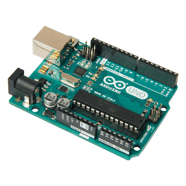
Arduino Arduino Uno Rev3
Arduino Uno is an open-source microcontroller board based on the ATmega328P. It has 14 digital input/output pins (of which 6 can be used as PWM outputs), 6 analog inputs, a 16 MHz ceramic resonator (CSTCE16M0V53-R0), a USB connection, a power jack, an ICSP header and a reset button. It contains everything needed to support the microcontroller; simply connect it to a computer with a USB cable or power it with a AC-to-DC adapter or battery to get started. You can tinker with your Uno without worring too much about doing something wrong, worst case scenario you can replace the chip for a few dollars and start over again. 'Uno' means one in Italian and was chosen to mark the release of Arduino Software (IDE) 1.0. The Uno board and version 1.0 of Arduino Software (IDE) were the reference versions of Arduino, now evolved to newer releases. The Uno board is the first in a series of USB Arduino boards, and the reference model for the Arduino platform; for an extensive list of current, past or outdated boards see the Arduino index of boards. Specifications Microcontroller ATmega328P Operating Voltage 5 V Input Voltage (recommended) 7-12 V Input Voltage (limit) 6-20 V Digital I/O Pins 14 (of which 6 provide PWM output) PWM Digital I/O Pins 6 Analog Input Pins 6 DC Current per I/O Pin 20 mA DC Current for 3.3 V Pin 50 mA Flash Memory 32 KB (ATmega328P) of which 0.5 KB used by bootloader SRAM 2 KB (ATmega328P) EEPROM 1 KB (ATmega328P) Clock Speed 16 MHz LED_BUILTIN 13 Dimensions 68.6 x 53.4 mm Weight 25 g
€ 24,95
Members identical
-
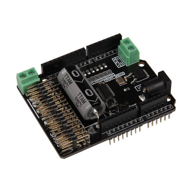
JOY-iT JOY-iT Motorino - Motor Control for Arduino
The Motorino board is an extension-board to control and use up to 16 PWM-controlled 5V-Servo-motors. The included clock generator ensures a very precise PWM signal and a very precise positioning. The board has 2 inputs for voltage from 4.8 V to 6 V which can be used for up to 11 A. With this input, a perfect power supply is always guaranteed and even bigger projects are no problem. The supply runs directly over the Motorino which provides a connection for voltage, ground and control. With the build in capacitor, the voltage is buffered which prevents a sudden voltage-drop at a high load. But there is also the possibility to connect another capacitor. The control and the programing can be done, as usual, with the Arduino. Manuals and code examples allows a quick introduction for beginners. Special features 16 Channels, own clock generator Input 1 Coaxial power connector 5.5 / 2.1 mm, 4.8-6 V / 5 A max Input 2 Screw-terminal, 4.8-6 V / 6 A max Communication 16 x PWM Compatible with Arduino Uno, Mega and may more microcontroller with Arduino compatible pinout Dimensions 69 x 24 x 56 mm Scope of supply Board, Manual, Retail package
€ 26,95
Members € 24,26
-
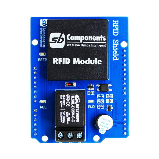
SB Components Ardi RFID Shield for Arduino Uno
Designed with convenience and security in mind, the Ardi RFID Shield is based on the EM-18 module, operating at a frequency of 125 KHz. This shield allows you to easily integrate RFID (Radio Frequency Identification) technology into your projects, enabling seamless identification and access control systems. Equipped with a powerful 1-channel optoisolated relay, the Ardi RFID Shield offers a reliable switching solution with a maximum DC rating of 30 V and 10 A, as well as an AC rating of 250 V and 7 A. Whether you need to control lights, motors, or other high-power devices, this shield provides the necessary functionality. Additionally, the Ardi RFID Shield features an onboard buzzer that can be utilized for audio feedback, allowing for enhanced user interaction and system feedback. With the onboard 2-indication LEDs, you can easily monitor the status of RFID card detection, power supply, and relay activation, providing clear visual cues for your project's operation. Compatibility is key, and the Ardi RFID Shield ensures seamless integration with the Arduino Uno platform. Paired with a read-only RFID module, this shield opens up a world of possibilities for applications such as access control systems, attendance tracking, inventory management, and more. Features Onboard 125 kHz EM18 RFID small, compact module Onboard High-quality relays Relay with Screw terminal and NO/NC interfaces Shield compatible with both 3.3 V and 5 V MCU Onboard 3 LEDs power, relay ON/OFF State and RFID Scan status Multi-tone Buzzer onboard for Audio alerts Mounts directly onto ArdiPi, Ardi32 or other Arduino compatible boards Specifications RFID operating Frequency: 125 kHz Reading distance: 10 cm, depending on TAG Integrated Antenna Relay Max Switching Voltage: 250 V AC/30 V DC Relay Max Switching Current: 7 A/10 A
€ 24,95
Members € 22,46
-

Elektor Labs Elektor Arduino MultiCalculator
The Elektor MultiCalculator Kit is an Arduino-based multifunction calculator that goes beyond basic calculations. It offers 22 functions including light and temperature measurement, differential temperature analysis, and NEC IR remote control decoding. The Elektor MultiCalculator is a handy tool for use in your projects or for educational purposes. The kit features a Pro Mini module as the computing unit. The PCB is easy to assemble using through-hole components. The enclosure consists of 11 acrylic panels and mounting materials for easy assembly. Additionally, the device is equipped with a 16x2 alphanumeric LCD, 20 buttons, and temperature sensors. The Elektor MultiCalculator is programmable with the Arduino IDE through a 6-way PCB header. The available software is bilingual (English and Dutch). The calculator can be programmed with a programming adapter, and it is powered through USB-C. Modes of Operation Calculator 4-Ring Resistor Code 5-Ring Resistor Code Decimal to Hexadecimal and Character (ASCII) conversion Hexadecimal to Decimal and Character (ASCII) conversion Decimal to Binary and Character (ASCII) conversion Binary to Decimal and Hexadecimal conversion Hz, nF, capacitive reactance (XC) calculation Hz, µH, inductive reactance (XL) calculation Resistance calculation of two resistors connected in parallel Resistance calculation of two resistors connected in series Calculation of unknown parallel resistor Temperature measurement Differential temperature measurement T1&T2 and Delta (δ) Light measurement Stopwatch with lap time function Item counter NEC IR remote control decoding AWG conversion (American Wire Gauge) Rolling Dice Personalize startup message Temperature calibration Specifications Menu languages: English, Dutch Dimensions: 92 x 138 x 40 mm Build time: approx. 5 hours Included PCB and though-hole components Precut acrylic sheets with all mechanical parts Pro Mini microcontroller module (ATmega328/5 V/16 MHz) Programming adapter Waterproof temperature sensors USB-C cable Downloads Software
€ 49,95€ 39,95
Members identical
-
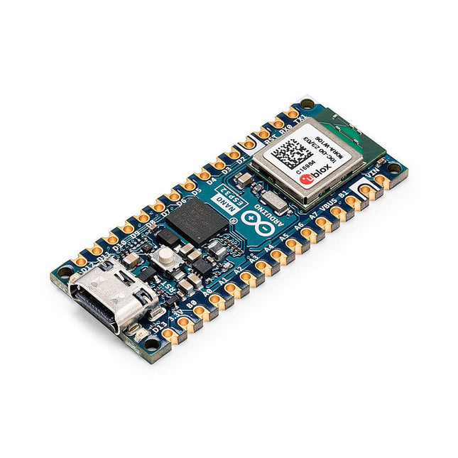
Arduino Arduino Nano ESP32
The Arduino Nano ESP32 (with and without headers) is a Nano form factor board based on the ESP32-S3 (embedded in the NORA-W106-10B from u-blox). This is the first Arduino board to be based fully on an ESP32, and features Wi-Fi, Bluetooth LE, debugging via native USB in the Arduino IDE as well as low power. The Nano ESP32 is compatible with the Arduino IoT Cloud, and has support for MicroPython. It is an ideal board for getting started with IoT development. Features Tiny footprint: Designed with the well-known Nano form factor in mind, this board's compact size makes it perfect for embedding in standalone projects. Wi-Fi and Bluetooth: Harness the power of the ESP32-S3 microcontroller, well-known in the IoT realm, with full Arduino support for wireless and Bluetooth connectivity. Arduino and MicroPython support: Seamlessly switch between Arduino and MicroPython programming with a few simple steps. Arduino IoT Cloud compatible: Quickly and easily create IoT projects with just a few lines of code. The setup takes care of security, allowing you to monitor and control your project from anywhere using the Arduino IoT Cloud app. HID support: Simulate human interface devices, such as keyboards or mice, over USB, opening up new possibilities for interacting with your computer. Specifications Microcontroller u-blox NORA-W106 (ESP32-S3) USB connector USB-C Pins Built-in LED pins 13 Built-in RGB LED pins 14-16 Digital I/O pins 14 Analog input pins 8 PWM pins 5 External interrupts All digital pins Connectivity Wi-Fi u-blox NORA-W106 (ESP32-S3) Bluetooth u-blox NORA-W106 (ESP32-S3) Communication UART 2x I²C 1x, A4 (SDA), A5 (SCL) SPI D11 (COPI), D12 (CIPO), D13 (SCK). Use any GPIO for Chip Select (CS) Power I/O Voltage 3.3 V Input voltage (nominal) 6-21 V Source Current per I/O pin 40 mA Sink Current per I/O pin 28 mA Clock speed Processor Up to 240 MHz Memory ROM 384 kB SRAM 512 kB External Flash 128 Mbit (16 MB) Dimensions 18 x 45 mm Downloads Datasheet Schematics
€ 23,95€ 17,95
Members identical
-
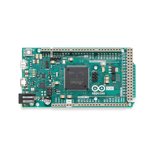
Arduino Arduino Due with Headers
The board contains everything needed to support the microcontroller; simply connect it to a computer with a micro-USB cable or power it with an AC-to-DC adapter or battery to get started. The Due is compatible with all Arduino shields that work at 3.3V and are compliant with the 1.0 Arduino pinout. The Due follows the 1.0 pinout: TWI: SDA and SCL pins that are near to the AREF pin. IOREF: allows an attached shield with the proper configuration to adapt to the voltage provided by the board. This enables shield compatibility with a 3.3V board like the Due and AVR-based boards which operate at 5V. An unconnected pin, reserved for future use. Specifications Operating Voltage 3.3 V Input Voltage 7-12 V Digital I/O 54 Analog Input Pins 12 Analog Output Pins 2 (DAC) Total DC Output Current on all I/O Lines 130 mA DC Current per I/O Pin 20 mA DC Current for 3.3 V Pin 800 mA DC Current for 5 V Pin 800 mA Flash Memory 512 KB all available for the user applications SRAM 96 KB Clock Speed 84 MHz Length 101.52 mm Width 53.3 mm Weight 36 g Please note: Unlike most Arduino boards, the Arduino Due board runs at 3.3V. The maximum voltage that the I/O pins can tolerate is 3.3V. Applying voltages higher than 3.3V to any I/O pin could damage the board.
€ 44,95
Members € 40,46
-
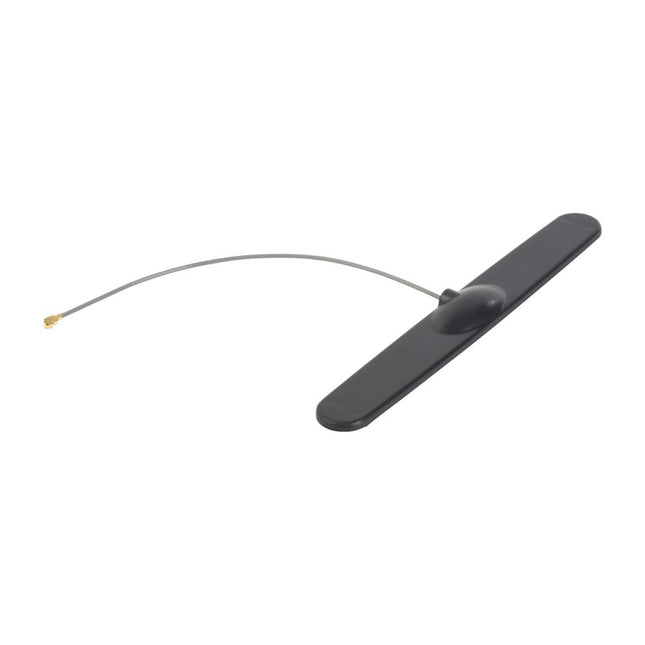
Arduino GSM Antenna for Arduino MKR Boards
This antenna works with Arduino MKR FOX 1200 / Ardunio MKR GSM 1400 / Arduino MKR WAN 1300 as well. Antenna connection: U.FL GSM 433/868/915 MHz
€ 7,95
Members € 7,16
-
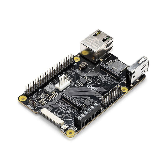
Arduino Arduino Portenta HAT Carrier
Portenta HAT Carrier is a reliable and robust carrier that transforms Portenta X8 into an industrial single board computer compatible with Raspberry Pi HATs and cameras. It is ideal for multiple industrial applications such as building automation and machine monitoring. Compatible also with Portenta H7 and Portenta C33, Portenta HAT Carrier provides easy access to multiple peripherals – including CAN, Ethernet, microSD and USB – and further extends any Portenta application. It is great for prototyping and ready for scaling up, it extends the features found on a typical Raspberry Pi Model B. Debug quickly with dedicated JTAG pins and keeps heat manageable under intense workloads with a PWM fan connector. Control actuators or read analog sensors via the additional 16x analog I/Os. Add industrial machine vision solutions to any project by leveraging the onboard camera connector. Features Add Raspberry Pi HATs to your Portenta projects Quickly access CAN, USB, and Ethernet peripherals Leverage onboard MicroSD card to log data Enjoy simple debugging through the onboard JTAG pins Easily control actuators and read sensors via 16x analog I/Os Leveraging the onboard camera connector for machine vision Portenta takes you from prototype to high-performance Portenta HAT Carrier offers you a frictionless Linux prototyping experience and unlocks the ability for integrated real-time MCU solutions. Portenta HAT Carrier extends Portenta SOMs for faster, easier and more efficient testing for your ideas while also ensuring the capabilities and industrial-grade performances the Portenta range is known for. Extend the Raspberry Pi ecosystem for commercial applications Combine the ease of use, accessibility and incredible support from both the Arduino and Raspberry Pi communities for your next project with the carrier designed to combine and extend MPU and MCU applications for the development of advanced commercial solutions. Specifications Connectors High-density connectors compatible with Portenta products 1x USB-A female connector 1x Gigabit Ethernet connector (RJ45) 1x CAN FD with onboard transceiver 1x MIPI Camera connector 1x MicroSD card slot 1x PWM fan connector 40-pin header connector allowing compatibility with Raspberry Pi HATs 16-pin analog header connectors, including: 8x analog inputs 1x GPIO 1xUART without flow control 2x PWM pins 1x LICELL pin for Portenta's RTC power Interfaces CAN FD UART SAI ANALOG GPIO SPI I²C I²S PWM Debugging Onboard 10x pin 1.27 mm JTAG connector Power From onboard screw terminal block allowing: 7-32 V power supply, powering both the carrier and the connected Portenta 5 V power supply From USB-C on Portenta From 5 V on 40-pin header connector Dimensions 85 x 56 mm Downloads Datasheet Schematics
€ 54,95€ 39,95
Members identical
-
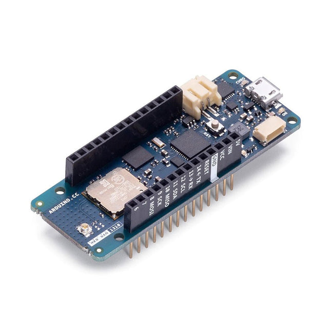
Arduino Arduino MKR WAN 1310
Ever wanted an automated house? Or a smart garden? Well, now it’s easy with the Arduino IoT Cloud compatible boards. It means: you can connect devices, visualize data, control and share your projects from anywhere in the world. Whether you’re a beginner or a pro, we have a wide range of plans to make sure you get the features you need. Connect your sensors and actuators over long distances harnessing the power of the LoRa wireless protocol or throughout LoRaWAN networks. The Arduino MKR WAN 1310 board provides a practical and cost effective solution to add LoRa connectivity to projects requiring low power. This open source board can be connected to the Arduino IoT Cloud. Better and More Efficient The MKR WAN 1310, brings in a series of improvements when compared to its predecessor, the MKR WAN 1300. While still based on the Microchip SAMD21 low power processor, the Murata CMWX1ZZABZ LoRa module, and the MKR family’s characteristic crypto chip (the ECC508), the MKR WAN 1310 includes a new battery charger, a 2 MByte SPI Flash, and improved control of the board’s power consumption. Improved Battery Power The latest modifications have considerably improved the battery life on the MKR WAN 1310. When properly configured, the power consumption is now as low as 104 uA! It is also possible to use the USB port to supply power (5 V) to the board; run the board with or without batteries – the choice is yours. On-board Storage Data logging and other OTA (Over The Air) functions are now possible since the inclusion of the on board 2 MByte Flash. This new exciting feature will let you transfer configuration files from the infrastructure onto the board, create your own scripting commands, or simply store data locally to send it whenever the connectivity is best. Whilst the MKR WAN 1310’s crypto chip adds further security by storing credentials & certificates in the embedded secure element. These features make it the perfect IoT node and building block for low-power wide-area IoT devices. Specifications The Arduino MKR WAN 1310 is based on the SAMD21 microcontroller. Microcontroller SAMD21 Cortex-M0+ 32-bit low power ARM MCU (datasheet) Radio module CMWX1ZZABZ (datasheet) Board power supply (USB/VIN) 5 V Secure element ATECC508 (datasheet) Supported batteries Rechargeable Li-Ion, or Li-Po, 1024 mAh minimum capacity Circuit operating voltage 3.3 V Digital I/O pins 8 PWM pins 13 (0 .. 8, 10, 12, 18 / A3, 19 / A4) UART 1 SPI 1 I²C 1 Analog input pins 7 (ADC 8/10/12 bit) Analog output pins 1 (DAC 10 bit) External interrupts 8 (0, 1, 4, 5, 6, 7, 8, 16 / A1, 17 / A2) DC current per I/O pin 7 mA CPU flash memory 256 KB (internal) QSPI flash memory 2 MByte (external) SRAM 32 KB EEPROM No Clock speed 32.768 kHz (RTC), 48 MHz LED_BUILTIN 6 USB Full-Speed USB Device and embedded Host Antenna gain 2 dB (bundled pentaband antenna) Carrier frequency 433/868/915 MHz Dimensions 67.64 x 25 mm Weight 32 g Downloads Eagle Files Schematics Fritzing Pinout
€ 59,95
Members € 53,96
-
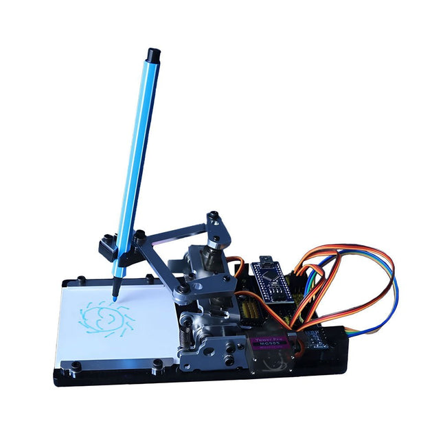
Generic Arduino-controlled Drawing Robot
This versatile plotter robot arm DIY kit for Arduino is equipped with MG90S metal gear servo motors to ensure precise and stable drawing movements. Features Fully compatible with Arduino IDE, includes complete source code for easy development and customization. Equipped with robust MG90S metal gear servo motors for accuracy and durability. Includes a Bluetooth module enabling wireless operation via a dedicated app. Specially designed robotic arm tip securely holds pens or markers with a diameter of 8-10 mm, ideal for sketches and detailed drawings. Included Arduino-compatible Nano motherboard Nano expansion board Bluetooth module MG90S all-metal gear servo motors Aluminum structural frame Thickened stable base plate Screw and fastening accessories Connecting wires USB data cable
€ 64,95€ 44,95
Members identical
-
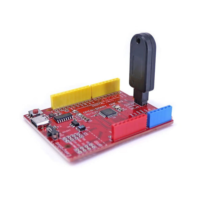
Generic Auto Bootloader/Programmer for Arduino Uno R3
This programmer is specifically designed for burning bootloaders (without a computer) on Arduino-compatible ATmega328P/ATmega328PB development boards. Simply plug the programmer into the ICSP interface to re-burn the bootloader. It’s also compatible with new chips, provided the IC is functional. Note: Burning a bootloader erases all previous chip data. Features Working voltage: 3.1-5.3 V Working current: 10 mA Compatible with Arduino Uno R3 based boards (ATmega328P or ATmega328PB) Dimensions: 39.6 x 15.5 x 7.8 mm
€ 14,95€ 7,95
Members identical


