Search results for "mikrocontroller OR module"
-
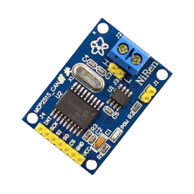
Makerfabs CAN Module MCP2515
This CAN Module is based on the CAN bus controller MCP2515 and CAN transceiver TJA1050. With this module, you will easy to control any CAN Bus device by SPI interface with your MCU, such as Arduino Uno and so on. Features Support CAN V2.0B Communication rate up to 1 MB/s Working Voltage: 5 V Working Current: 5 mA Interface: SPI Downloads MCP2515 Datasheet TJA1050 Datasheet
€ 9,95
Members € 8,96
-
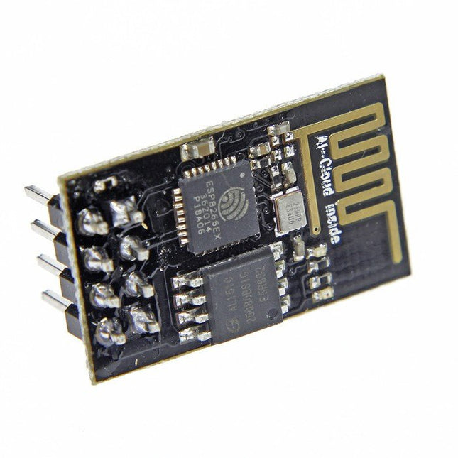
Espressif ESP8266 ESP-01 WiFi Module
The ESP8266 is an impressive, low cost WiFi module suitable for adding WiFi functionality to an existing microcontroller project via a UART serial connection. The module can even be reprogrammed to act as a standalone WiFi connected device – just add power! 802.11 b/g/n protocol Wi-Fi Direct (P2P), soft-AP Integrated TCP/IP protocol stack This module is a self-contained SOC (System On a Chip) that doesn’t necessarily need a microcontroller to manipulate inputs and outputs as you would normally do with an Arduino , for example, because the ESP-01 acts as a small computer. Thus, you can give a microcontroller internet access like the Wi-Fi shield does to the Arduino, or you can simply program the ESP8266 to not only have access to a Wi-Fi network, but to act as a microcontroller as well, which makes the ESP8266 very versatile.
€ 7,50
Members € 6,75
-
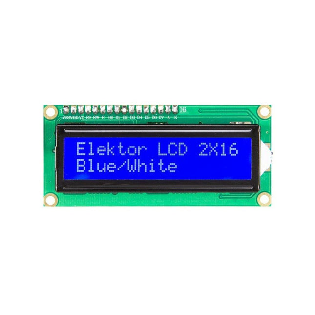
Kuongshun 2x16 Character LCD Module (blue/white)
2x16 Character LCD Module (blue/white) Pin No. Pin Name Descriptions 1 VSS Ground 2 VDD Supply voltage for logic 3 V0 Input voltage for LCD 4 RS Data / Instruction Regster Select (H : Data signal, L : Instruction signal) 5 R/W Read / Write (H : Read mode, L : Write mode) 6 E Enable signal 7 DB0 Data bit 0 8 DB1 Data bit 1 9 DB2 Data bit 2 10 DB3 Data bit 3 11 DB4 Data bit 4 12 DB5 Data bit 5 13 DB6 Data bit 6 14 DB7 Data bit 7 15 LED_A Backlight Anode 16 LED_K Backlight Cathode
€ 5,95
Members € 5,36
-
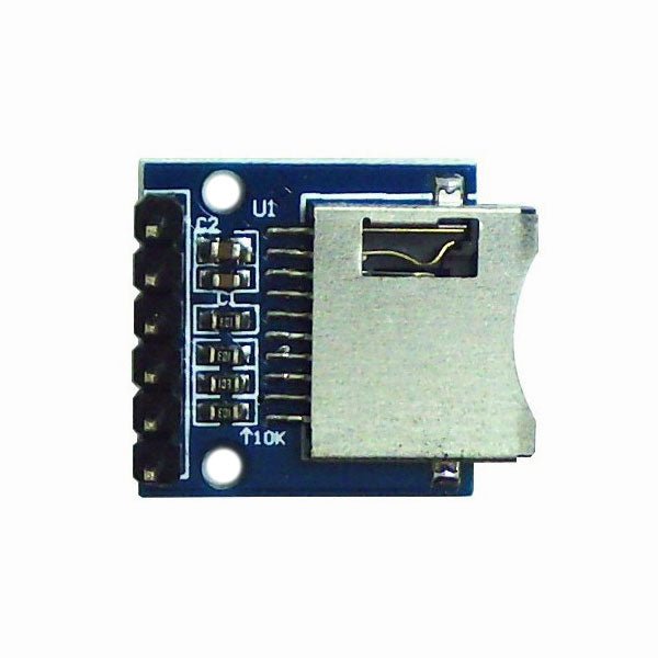
Kuongshun miniSD Card Module
miniSD Card Module
€ 3,95
Members € 3,56
-

Würth Abc of Power Modules (E-book)
Functionality, structure and handling of a power module For readers with first steps in power management the “Abc of Power Modules” contains the basic principles necessary for the selection and use of a power module. The book describes the technical relationships and parameters related to power modules and the basis for calculation and measurement techniques. Contents Basics This chapter describes the need of a DC/DC voltage converter and its basic functionality. Furthermore, various possibilities for realizing a voltage regulator are presented and the essential advantages of a power module are mentioned. Circuit topologies Circuit concepts, buck and boost topologies very frequently used with power modules are explained in detail and further circuit topologies are introduced. Technology, construction and regulation technology The mechanical construction of a power module is presented, which has a significant influence on EMC and thermal performance. Furthermore, control methods are explained and circuit design tips are provided in this chapter. Measuring methods Meaningful measurement results are absolutely necessary to assess a power module. The relevant measurement points and measurement methods are described in this chapter. Handling The aspects of storage and handling of power modules are explained, as well as their manufacturing and soldering processes. Selection of a power modules Important parameters and criteria for the optimal selection of a power module are presented in this section.
€ 8,99
Members € 7,19
-
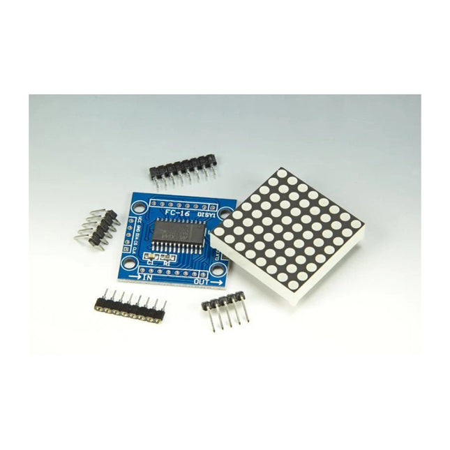
Elektor Labs MAX7219 Dot Matrix Module (Set of 8)
Scrolling text display with eight 8 x 8 LED dot matrix displays (512 LEDs in total). Built around an ESP-12F Wi-Fi module (ESP8266-based) programmed in the Arduino IDE. ESP8266 web server allows control of displayed text, scroll delay and brightness with a mobile phone or other Wi-Fi-connected (portable) device. Features 10 MHz Serial Interface Individual LED Segment Control Decode/No-Decode Digit Selection 150 µA Low-Power Shutdown (Data Retained) Digital and Analog Brightness Control Display Blanked on Power-Up Drive Common-Cathode LED Display Slew-Rate Limited Segment Drivers for Lower EMI (MAX7221) SPI, QSPI, MICROWIRE Serial Interface (MAX7221) 24-Pin DIP and SO Packages
€ 19,95€ 9,95
Members identical
-
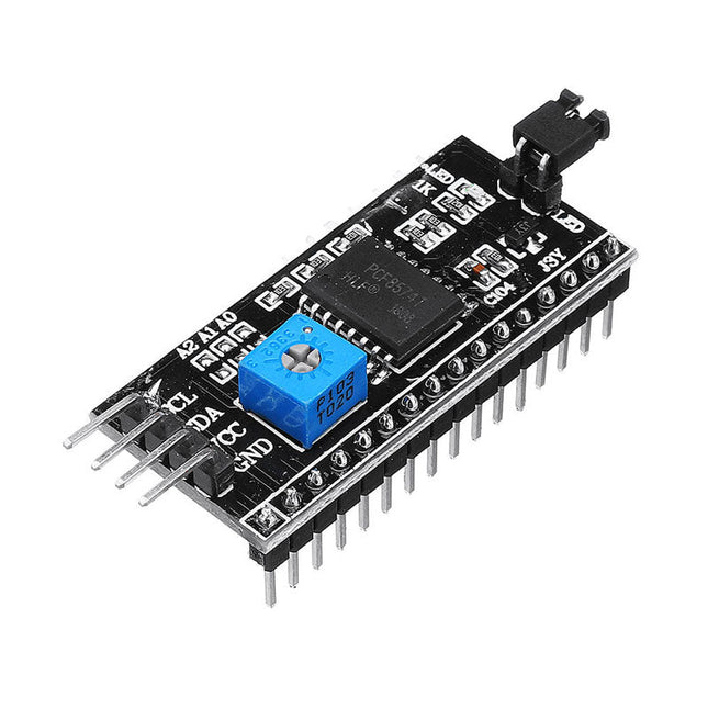
Kuongshun IIC/I²C Serial Interface Adapter Module
This is another great IIC/I²C/TWI/SPI Serial Interface. As the pin resources of controller is limited, your project may be not able to use normal LCD shield after connected with a certain quantity of sensors or SD card. However, with this I²C interface module, you will be able to realize data display via only 2 wires. If you already has I²C devices in your project, this LCD module actually cost no more resources at all. It is fantastic for based project. I²C Address: 0X20~0X27 (the original address is 0X20,you can change it yourself) The backlight and contrast is adjusted by potentiometer Comes with 2 IIC interface, which can be connected by Dupont Line or IIC dedicated cable I²C Address: 0x27 (I²C Address: 0X20~0X27 (the original address is 0X27,you can change it yourself) Specifications Compatible for 1602 LCD Supply voltage: 5 V Weight: 5 g Size: 5.5 x 2.3 x 1.4 cm
€ 4,95
Members € 4,46
-
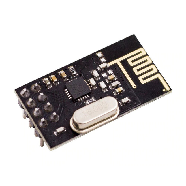
Kuongshun nRF24L01+ Wireless Transceiver Module (2.4 GHz)
NRF24L01 is a universal ISM band monolithic transceiver chip works in the 2.4-2.5 GHz. Features Wireless transceiver including: Frequency generator, enhanced type, SchockBurstTM, mode controller, power amplifier, crystal amplifier, modulator, demodulator The output power channel selection and protocol settings can be set extremely low current consumption, through the SPI interface As the transmit mode, the transmit power is 6 dBm, the current is 9.0 mA, the accepted mode current is 12.3 mA, the current consumption of the power-down mode and standby mode are lower Built-in 2.4 GHz antenna, supports up to six channels of data reception Size: 15 x 29 mm (including antenna)
€ 7,95
Members € 7,16
-
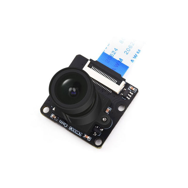
Waveshare Waveshare SC3336 3 MP Camera Module (B)
This camera module adopts a SmartSens SC3336 sensor chip with 3 MP resolution. It features high sensitivity, high SNR, and low light performance and it is capable of a more delicate and vivid night vision imaging effect, and can better adapt to ambient light changes. Also, it is compatible with Luckfox Pico series boards. Specifications Sensor Sensor: SC3336 CMOS size: 1/2.8" Pixels: 3 MP Static resolution: 2304x1296 Maximum video frame rate: 30fps Shutter: Rolling shutter Lens Focal length: 3.95 mm Aperture: F2.0 FOV: 98.3° (diagonal) Distortion: <33% Focusing: Manual focus Downloads Wiki
€ 16,95€ 8,50
Members identical
-

SparkFun SparkFun Artemis Module – Low Power Machine Learning BLE Cortex-M4F
The flexibility of the Artemis module starts with SparkFun's Arduino core. You can program and use the Artemis module just like you would an Uno or any other Arduino. The time to first blink is just 5 minutes away! We built the core from the ground up, making it fast and as lightweight as possible. Next is the module itself. Measuring 10 x 15 mm, the Artemis module has all the support circuitry you need to use the fantastic Ambiq Apollo3 processor in your next project. We're proud to say the SparkFun Artemis module is the first open-source hardware module with the design files freely and easily available. We've carefully designed the module so that implementing Artemis into your design can be done with low-cost 2-layer PCBs and 8mil trace/space. Made in the USA at SparkFun's Boulder production line, the Artemis module is designed for consumer-grade products. This truly differentiates the Artemis from its Arduino brethren. Ready to scale your product? The Artemis will grow with you beyond the Uno footprint and Arduino IDE. Additionally, the Artemis has an advanced HAL (hardware abstraction layer), allowing users to push the modern Cortex-M4F architecture to its limit. The SparkFun Artemis Module is fully FCC/IC/CE certified and is available in full tape and reel quantities. With 1M flash and 384k RAM, you'll have plenty of room for your code. The Artemis module runs at 48MHz with a 96MHz turbo mode available and with Bluetooth to boot!
€ 12,95
Members € 11,66
-
Espressif ESP-12F - ESP8266-based Wi-Fi Module
This Wi-Fi module is based on the popular ESP8266 chip. The module is FCC and CE certified and RoHS compliant. Fully compatible with ESP-12E. 13 GPIO pins, 1 analog input, 4 MB flash memory.
€ 8,95
Members € 8,06
-
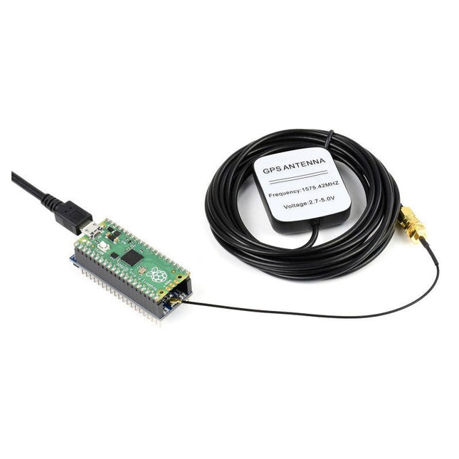
Waveshare Waveshare L76B GNSS Module for Raspberry Pi Pico
The Pico-GPS-L76B is a GNSS module designed for Raspberry Pi Pico, with multi satellite systems support including GPS, BDS, and QZSS. It has advantages such as fast positioning, high accuracy, and low power consumption, etc. Combined with the Raspberry Pi Pico, it's easy to use global navigating function.Features Standard Raspberry Pi Pico header, supports Raspberry Pi Pico series boards Multi satellite systems support: GPS, BDS, and QZSS EASY, self track prediction technology, help quick positioning AlwaysLocate, intelligent controller of periodic mode for power saving Supports D-GPS, SBAS (WAAS/EGNOS/MSAS/GAGAN) UART communication baudrate: 4800~115200bps (9600bps by default) Onboard battery holder, supports ML1220 rechargeable cell, for preserving ephemeris information and hot starts 4x LEDs for indicating the module operating status Comes with development resources and manual (Raspberry Pi Pico C/C++ and MicroPython examples) Specifications GNSS Frequency band:GPS L1 (1575.42 Mhz)BD2 B1 (1561.098 MHz) Channels: 33 tracking ch, 99 acquisition ch, 210 PRN ch C/A code SBAS: WAAS, EGNOS, MSAS, GAGAN Horizontal position accuracy(autonomous positioning) <2.5 m CEP Time-To-First-Fix @ -130 dBm(EASY enabled) Cold starts: <15s Warm starts: <5s Hot starts: <1s Sensitivity Acquisition: -148 dBm Tracking: -163 dBm Re-acquisition: -160 dBm Dynamic performance Altitude (max): 18000 m Velocity (max): 515 m/s Acceleration (max): 4 g Others Communication interface UART Baudrate 4800~115200bps (9600bps by default) Update rate 1 Hz (default), 10 Hz (max) Protocols NMEA 0183, PMTK Power supply voltage 5 V Operating current 13 mA Overall current consumption < 40 mA@5 V (Continue mode) Operating temperature -40℃ ~ 85℃ Dimensions 52 × 21 mm Included 1x Pico-GPS-L76B 1x GPS Antenna
€ 21,95
Members € 19,76


