An Introduction to RISC-V
RISC-V is an Instruction Set Architecture (ISA) that is both free and open. This means that the RISC-V ISA itself does not require a licensing fee, although individual implementations may do so. The RISC-V ISA is curated by a non-profit foundation with no commercial interest in products or services that use it, and it is possible for anyone to submit contributions to the RISC-V specifications. The RISC-V ISA is suitable for applications ranging from embedded microcontrollers to supercomputers.
This book will first describe the 32-bit RISC-V ISA, including both the base instruction set as well as the majority of the currently-defined extensions. The book will then describe, in detail, an open-source implementation of the ISA that is intended for embedded control applications. This implementation includes the base instruction set as well as a number of standard extensions.
After the description of the CPU design is complete the design is expanded to include memory and some simple I/O. The resulting microcontroller will then be implemented in an affordable FPGA development board (available from Elektor) along with a simple software application so that the reader can investigate the finished design.
This highly sensitive source picoammeter is designed for measuring and logging very small currents down to the pA range – making it an ideal instrument for scientific and research applications, including physics, materials science and electron microscopy.
Full-featured at an affordable price, the SPA100 combines sensitivity, accuracy and stability to allow users to measure low currents with high precision as well as conveniently source bias voltages for experimentation. SPA100 also doubles as an ultra-high resistance meter, measuring accurately into the teraohm range.
The SPA100 connects to PC via USB and utilises the complimentary software SPA – enabling users to easily measure, graph and capture readings with timestamps and measurement stability information.
Features
Input: ±2 mA to ±200 pA in 8 ranges
Accuracy and Resolution (2 Hz):
±2 mA range: ±0.1%, resolution <20 nA
±200 uA range: ±0.1%, resolution <2 nA
±20 uA range: ±0.2%, resolution <200 pA
±2 uA range: ±0.2%, resolution <20 pA
±200 nA range: ±0.5%, resolution <2 pA
±20 nA range: ±0.5%, resolution <200 fA
±2 nA range: ±1.0%, resolution <20 fA
±200 pA range: ±1.5%, resolution <2 fA
Sample rate: 2 Hz (18 bit) or 10 Hz (16 bit)
Adjustable filter: 1 sample to 64 samples
Output voltage: -40 V to +40 V (in 1 V increments), output resistance 2.7 Kohms
Resistance Measurement: ~1 Kohms to 40 Tohms (e.g 40 V source, 1 pA measure)
Accuracy: >±0.5% 1 Mohm to 1 Tohm
Powered via USB 2.0 (instrument uses up to 0.3 A when in-use)
Included
1x SPA100 Source Picoammeter
1x USB cable
Downloads
Manual
Software
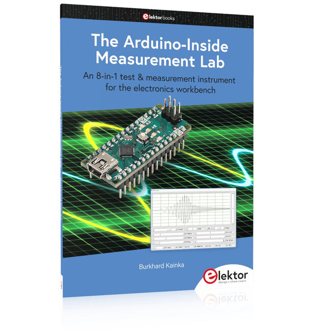
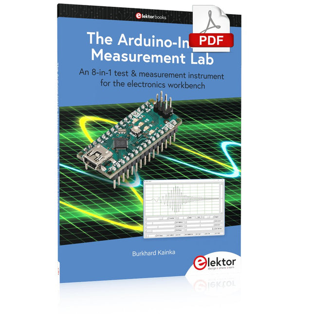
An 8-in-1 test & measurement instrument for the electronics workbench
A well-equipped electronics lab is crammed with power supplies, measuring devices, test equipment and signal generators. Wouldn‘t it be better to have one compact device for almost all tasks? Based on the Arduino, a PC interface is to be developed that’s as versatile as possible for measurement and control. It simply hangs on a USB cable and – depending on the software – forms the measuring head of a digital voltmeter or PC oscilloscope, a signal generator, an adjustable voltage source, a frequency counter, an ohmmeter, a capacitance meter, a characteristic curve recorder, and much more.
The circuits and methods collected here are not only relevant for exactly these tasks in the "MSR" electronics lab, but many details can also be used within completely different contexts.
Errata/Updates
In the programs printed, all instances of “be()” should read: sei().
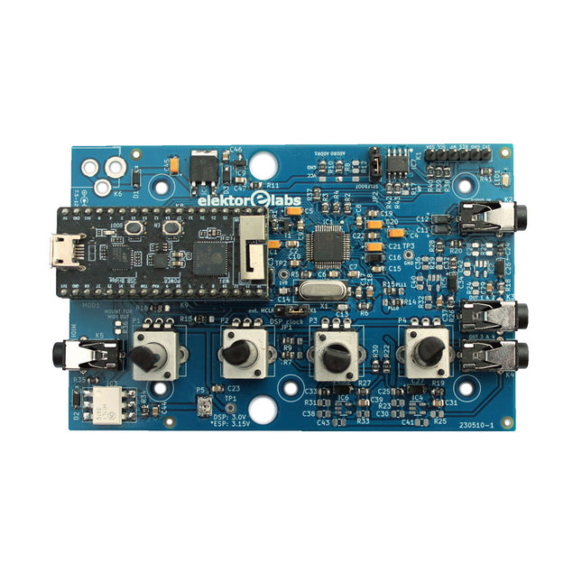
The Elektor Audio DSP FX Processor combines an ESP32 microcontroller and an ADAU1701 Audio DSP from Analog Devices. Besides a user-programmable DSP core, the ADAU1701 has high-quality analog-to-digital and digital-to-analog converters built-in and features an I²S port. This makes it suitable as a high-quality audio interface for the ESP32.
Programs for the ESP32 can be created with Arduino, Platform IO, CMake or by using the Espressif IDF in another way. Programs for the ADAU7101 audio DSPs are created with the free visual programming tool SigmaStudio by dragging and dropping pre-defined algorithm blocks on a canvas.
Applications
Bluetooth/Wi-Fi audio sink (e.g. loudspeaker) & source
Guitar effect pedal (stomp box)
Music synthesizer
Sound/function generator
Programmable cross-over filter for loudspeakers
Advanced audio effects processor (reverb, chorus, pitch shifting, etc.)
Internet-connected audio device
DSP experimentation platform
Wireless MIDI
MIDI to CV converter
and many more...
Specifications
ADAU1701 28-/56-bit, 50-MIPS digital audio processor supporting sampling rates of up to 192 kHz
ESP32 32-bit dual-core microcontroller with Wi-Fi 802.11b/g/n and Bluetooth 4.2 BR/EDR and BLE
2x 24-bit audio inputs (2 V RMS, 20 kΩ)
4x 24-bit audio outputs (0.9 V RMS, 600 Ω)
4x Control potentiometer
MIDI in- and output
I²C expansion port
Multi-mode operation
Power supply: 5 V DC USB or 7.5-12 V DC (barrel jack, center pin is GND)
Current consumption (average): 200 mA
Included
1x ESP32 Audio DSP FX Processor board (assembled)
1x ESP32-PICO-KIT
2x Jumpers
2x 18-pin headers (female)
4x 10 KB potentiometers
Downloads
Documentation
GitHub
This module includes an integrated trace antenna, fits the IC to an FCC-approved footprint, and includes decoupling and timing mechanisms that would need to be designed into a circuit using the bare nRF52840 IC. The Bluetooth transceiver included on the nRF52840 boasts a BT 5.1 stack. It supports Bluetooth 5, Bluetooth mesh, IEEE 802.15.4 (Zigbee & Thread) and 2.4Ghz RF wireless protocols (including Nordic's proprietary RF protocol) allowing you to pick which option works best for your application.
Features
ARM Cortex-M4 CPU with a floating-point unit (FPU)
1MB internal Flash -- For all of your program, SoftDevice, and file-storage needs!
256kB internal RAM -- For your stack and heap storage.
Integrated 2.4GHz radio with support for:
Bluetooth Low Energy (BLE) -- With peripheral and/or central BLE device support
Bluetooth 5 -- Mesh Bluetooth!
ANT -- If you want to turn the device into a heart-rate or exercise monitor.
Nordic's proprietary RF protocol -- If you want to communicate, securely, with other Nordic devices.
Every I/O peripheral you could need.
USB -- Turn your nRF52840 into a USB mass-storage device, use a CDC (USB serial) interface, and more.
UART -- Serial interfaces with support for hardware flow-control if desired.
I²C -- Everyone's favourite 2-wire bi-directional bus interface
SPI -- If you prefer the 3+-wire serial interface
Analogue-to-digital converters (ADC) -- Eight pins on the nRF52840 Mini Breakout support analogue inputs
PWM -- Timer support on any pin means PWM support for driving LEDs or servo motors.
Real-time clock (RTC) -- Keep close track of seconds and milliseconds, also supports timed deep-sleep features.
Three UARTs
Primary tied to USB interface. Two hardware UARTs.
Two I²C Buses
Two SPI Buses
Secondary SPI Bus primarily used for Flash IC.
PDM Audio Processing
Two Analog Inputs
Two Dedicated Digital I/O Pins
Two Dedicated PWM Pins
Eleven General Purpose I/O Pins
With a Cortex-M4F with BLE 5.0 running up to 96MHz and with as low power as 6uA per MHz (less than 5mW), the M.2 MicroMod connector allows you to plug in a MicroMod Carrier Board with any number of peripherals. Let's have a look at what this processor board has to offer! If you need Machine Learning capabilities, Bluetooth, I²C functionality to connect to all our amazing Qwiic boards, and more the Artemis Processor is the perfect choice for your MicroMod Carrier Board. At the heart of SparkFun's Artemis Module is Ambiq Micro's Apollo3 processor, whose ultra-efficient ARM Cortex-M4F processor is spec’d to run TensorFlow Lite using only 6uA/MHz. We've routed two I²C buses, eight GPIO, dedicated digital, analogue, and PWM pins, multiple SPI as well as QuadSPI, and Bluetooth to boot. You really can't go wrong with this processor. Grab one today, pick up a compatible carrier board, and get hacking! Features 1 M Flash / 384 k RAM 48 MHz / 96 MHz turbo available 6uA/MHz (operates less than 5mW at full operation) 48 GPIO - all interrupt capable 31 PWM channels Built-in BLE radio and antenna 10 ADC channels with 14-bit precision with up to 2.67 million samples per second effective continuous, multi-slot sampling rate 2 channel differential ADC 2 UARTs 6 I²C buses 6 SPI buses 2/4/8-bit SPI bus PDM interface I²S Interface Secure 'Smart Card' interface FCC/IC/CE Certified (ID Number 2ASW8-ART3MIS)
1x USB dedicated for programming and debugging 1x UART with flow control 2 x I²C 1 x SPI 1 x Quad-SPI 8 x Fast GPIO 2 x Digital Pins 2 x Analog Pins 2 x PWM 1 x Differential ADC pair Status LED VIN Level ADC
The board provides you with an economical and easy to use development platform if you're needing more power with minimal working space. With the M.2 MicroMod connector, connecting your SAMD51 Processor is a breeze. Simply match up the key on your processor's bevelled edge connector to the key on the M.2 connector and secure it with a screw (included with all Carrier Boards). The SAMD51 is one of the most powerful and economical microcontrollers available so to be able to add it to your MicroMod Carrier Board is a huge advantage for your project!
The ATSAMD51J20 utilizes a 32-bit ARM Cortex-M4 processor with Floating Point Unit (FPU), running up to 120MHz, up to 1MB of flash memory, up to 256KB of SRAM with ECC, up to 6 SERCOM interfaces, and other features. This MicroMod SAMD51 even comes flashed with the same convenient UF2 bootloader as the SAMD51 Thing Plus and the RedBoard Turbo.
Features
ATSAMD51J20 microcontroller
32-bit ARM Cortex-M4F MCU
Up to 120 MHz CPU speed
1 MB flash memory
256 KB SRAM
Up to 6 SERCOM interfaces
UF2 bootloader
1x USB dedicated for programming and debug (Host capable)
2x UARTs
2x I²C
1x SPI
1x CAN
11x GPIO
2x Digital Pins
2x Analog Pins
2x PWM
128 mbit / 16 MB (external) flash memory
Status LED
VIN Level ADC
With the M.2 MicroMod connector, connecting your ESP32 Processor is a breeze. Match up the key on your processor's bevelled edge connector to the key on the M.2 connector and secure it with a screw (included with all Carrier Boards). If you need to swap out your processor for a strong wireless option, make sure to check out the MicroMod ESP32! The ESP32 includes a laundry list of functionality, including the dual-core Tensilica LX6 microprocessor, 240MHz clock frequency, 520kB internal SRAM, integrated WiFi transceiver, integrated dual-mode Bluetooth, and hardware-accelerated encryption (AES, SHA2, ECC, RSA-4096). With this MicroMod processor board, you have access to 8 general use IO pins, dedicated analogue, digital, and PWM pins, as well as all the fan favourites - SPI, I²C, UART, and SDIO. Add to that 16MB flash storage and sleep current of around 500µA, and you've got a perfect storm of versatility. Features Dual-core Tensilica LX6 microprocessor Up to 240 MHz clock frequency 520 kB internal SRAM 128 mbit / 16 MB flash storage Integrated 802.11 BGN WiFi transceiver Integrated dual-mode Bluetooth (classic and BLE) 2.7-3.6 V operating range 500µA sleep current under hibernation 10-electrode capacitive touch support Hardware-accelerated encryption (AES, SHA2, ECC, RSA-4096) 1x USB dedicated for programming and debugging 1x UART 2x I²C 1x SPI 7x GPIO 2x Digital Pins 2x Analog Pins 2x PWM Status LED VIN Level ADC
An 8-in-1 test & measurement instrument for the electronics workbench
A well-equipped electronics lab is crammed with power supplies, measuring devices, test equipment and signal generators. Wouldn‘t it be better to have one compact device for almost all tasks? Based on the Arduino, a PC interface is to be developed that’s as versatile as possible for measurement and control. It simply hangs on a USB cable and – depending on the software – forms the measuring head of a digital voltmeter or PC oscilloscope, a signal generator, an adjustable voltage source, a frequency counter, an ohmmeter, a capacitance meter, a characteristic curve recorder, and much more.
The circuits and methods collected here are not only relevant for exactly these tasks in the "MSR" electronics lab, but many details can also be used within completely different contexts.
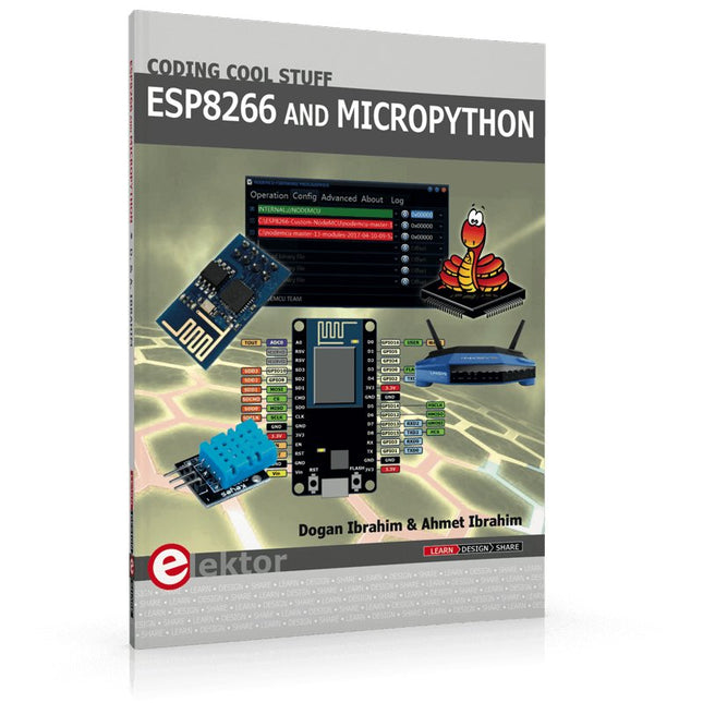
Recently, the development of a tiny chip called the ESP8266 has made it possible to interface any type of microcontroller to a Wi-Fi AP. The ESP8266 is a low-cost tiny Wi-Fi chip having fully built-in TCP/IP stack and a 32-bit microcontroller unit. This chip, produced by Shanghai based Chinese manufacturer Espressif System, is IEEE 802.11 b/g/n Wi-Fi compatible with on-chip program and data memory, and general purpose input-output ports. Several manufacturers have incorporated the ESP8266 chip in their hardware products (e.g. ESP-xx, NodeMCU etc) and offer these products as a means of connecting a microcontroller system such as the Android, PIC microcontroller or others to a Wi-Fi. The ESP8266 is a low-power chip and costs only a few Dollars.
ESP8266 and MicroPython – Coding Cool Stuff is an introduction to the ESP8266 chip and describes the features of this chip and shows how various firmware and programming languages such as the MicroPython can be uploaded to the chip. The main aim of the book is to teach the readers how to use the MicroPython programming language on ESP8266 based hardware, especially on the NodeMCU.
Several interesting and useful projects are given in the book to show how to use the MicroPython in NodeMCU type ESP8266 hardware:
Project “What shall I wear today?”: You will be developing a weather information system using a NodeMCU development board together with a Text-to-Speech processor module.
Project “The Temperature and Humidity on the Cloud”: You will be developing a system that will get the ambient temperature and humidity using a sensor and then store this data on the cloud so that it can be accessed from anywhere.
Project “Remote Web Based Control”: You will be developing a system that will remotely control two LEDs connected to a NodeMCU development board using an HTTP Web Server application.
A Handbook on DIY
Nowadays, security problems are rarely properly solved or correctly addressed. Electronic security is only part of the chain in making a system secure. Electronic security is usually addressed as network or software security, neglecting other aspects, but the chain is only as strong as its weakest link.
This book is about electronic hardware security, with an emphasis on problems that you can solve on a shoestring DIY budget. It deals mostly with secure communications, cryptosystems, and espionage. You will quickly appreciate that you can’t simply buy a trustworthy and reliable cryptosystem off the shelf. You will then realise that this applies equally to individuals, corporations, and governments.
If you want to increase your electronic security awareness in a world already overcrowded with networks of microphones and cameras, this is a book for you. Furthermore, if you want to do something DIY by designing and expanding upon simple electronic systems, please continue reading. Some of the devices described are already published as projects in the Elektor magazine. Some are still ideas yet to be worked out.
Complexity is the main enemy of security, so we'll try to keep to simple systems. Every chapter will analyse real-life espionage events or at least several hypothetical scenarios that will hopefully spark your imagination. The final goal is to build a security-conscious mindset (or “to get into a head of a spy”) which is necessary to recognise possible threats beforehand, to design a truly secure system.
Don’t bother reading if:
you think you and your secrets are 100% safe and secure
you think somebody else can effectively handle your security
you think conspiracy theories only exist in theory – Telefunken’s masterpiece the “FS-5000 Harpoon” was built on one!
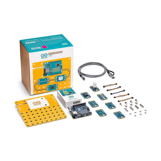
Build your first IoT devices with this kit by seamlessly integrating hardware and software without diving into complex theory.
Plug and Make Kit is the easiest way to get started with Arduino. It includes everything you need for your very first seven projects – as well as many more that our community shares and you can invent yourself!
Weather Report: Never get caught in the rain again, with a visual reminder to take an umbrella when needed
Hourglass: Who needs an egg timer? Customize your own digital hourglass
Eco Watch: Make sure your plants thrive in the perfect temperature and humidity
Game Controller: Level up with your very own HID (Human Interface Device) gamepad
Sonic Synth: Get one step closer to being a rockstar, DJ or sound engineer!
Smart Lights: Set the mood with your very own smart lamp
Touchless Lamp: Control lights with a simple gesture
Each idea is inspiration for a fun activity that will not only teach you the basics of do-it-yourself electronics but leave you with a great sense of accomplishment. You can make technology too!
With the innovative Modulino nodes, simply connect them sequentially using the onboard Qwiic connector of the Arduino Uno R4 WiFi. By utilizing one of the Arduino Cloud templates, you can swiftly transform your concept into a fully operational project.
Features
No extra tools needed, all you have to kick off you journey as maker is included in the kit.
No breadboard and no soldering are involved.
Build a fully functional IoT project, understanding its inner working, in under 45 minutes.
Start from the project you find more interesting, you define your own learning path.
Continue learning and working on your projects from any connected computer using the online Arduino ecosystem.
Modulino
Modulino are sensors and actuators that simply connect via the Uno R4 WiFi’s onboard Qwiic connector. You can connect more than one for more complex projects and never have to wonder which side goes where, because the connector is polarized.
Modulino Knob: for super-fine value adjustments
Modulino Pixels: eight LEDs to shine bright, dim down, or change color
Modulino Distance: a time-of-flight proximity sensor to measure distances with precision
Modulino Movement: to perfectly capture movements like pitch, roll or tilt
Modulino Buzzer: to generate your own alarm sounds or simple tunes
Modulino Thermo: a sensor for both temperature and humidity data
Modulino Buttons: three buttons for quick project navigation
Specifications
Board included
Arduino Uno R4 WiFi
Modulino nodes
Communications
I²C (over Qwiic connector)
Operational voltage
3.3 V
Modulino nodes included
Modulino Movement
LSM6DSOXTR
0x6A (0x6B)
Modulino Distance
VL53L4CDV0DH/1
0x29
Modulino Thermo
HS3003
0x44
Modulino Knob
PEC11J (STM32C011F4 for I²C communication)
0x76 (address can change via software)
Modulino Buzzer
PKLCS1212E4001-R1 (STM32C011F4 for I²C communication)
0x3C (address can change via software)
Modulino Pixels
8 LC8822-2020 (STM32C011F4 for I²C communication)
0x6C (address can change via software)
Modulino Buttons
3 push buttons plus 3 yellow LEDs (STM32C011F4 for I²C communication)
0x7C (address can change via software)
Included
1x Arduino Uno R4 WiFi
1x Modulino base
7x Modulino sensors
1x USB-C cable
7x Qwiic cables
24x Screws M3 (10 mm)
20x Nuts M3
4x Metal spacers
Downloads
Datasheet
Schematics