The QA403 is QuantAsylum's fourth-generation audio analyzer. The QA403 extends the functionality of the QA402 with improved noise and distortion performance, in addition to a flatter response at band edges. The compact size of the QA403 means you can take it just about anywhere.
Features
24-bit ADC/DAC
Up to 192 kS/s
Fully isolated from PC
Differential Input/Output
USB powered
Built-in Attenuator
Fast Bootup and Driverless
The QA403 is a driverless USB device, meaning it’s ready as soon as you plug it in. The software is free and it is quick and easy to move the hardware from one machine to the next. So, if you need to head to the factory to troubleshoot a problem or take the QA403 home for a work-from-home day, you can do it without hassle.
No-Cal Design
The QA403 comes with a factory calibration in its flash memory, ensuring consistent unit-to-unit performance. On your manufacturing line you can install another QA403 and be confident what you read on one unit will be very similar to the next unit. It is not expected that re-calibration will be required at regular intervals.
Measurements
Making basic measurements is quick and easy. In a few clicks you will understand the frequency response, THD(+N), gain, SNR and more of your device-under test.
Dynamic Range
The QA403 offers 8 gain ranges on the input (0 to +42 dBV in 6 steps), and 4 gain ranges on the output (-12 to +18 dBV in 10 dB steps). This ensures consistent performance over very wide ranges of input and output levels. The maximum AC input to the QA403 is +32 dBV = 40 Vrms. The maximum DC is ±40 V, and the maximum ACPEAK + DC = ±56 V.
Easy Programmability
The QA403 supports a REST interface, making it easy to automate measurements in just about any language you might anticipate. From Python to C++ to Visual Basic—if you know how to load a web page in your favorite language, you can control the QA403 remotely. Measurements are fast and responsive, usually with dozens of commands being processed per second.
Isolated and USB Powered
The QA403 is isolated from the PC, meaning you are measuring your DUT and not chasing some phantom ground loop. The QA403 is USB powered, like nearly all our instruments. If you are setting up remotely, throw a powered hub in your bag and your entire test setup can be running with a minimum of cables.
Goodbye Soundcard, Hello QA403
Tired of trying to make a soundcard work? The calibration nightmare? The lack of gain stages? The limited drive? Are you tired of dealing with the fixed input ranges? The worry that you might destroy it with too much DC or AC? Tired of the ground loops? That’s why QuantAsylum built the QA403.
Specifications
Dimensions
177 x 44 x 97 mm (W x H x D)
Weight
435 g
Case Material
Powder-coating Aluminum (2 mm thick front panel, 1.6 mm thick top/bottom)
Downloads
Datasheet
Manual
GitHub
Arduinonext is an initiative powered by an electronics and microcontrollers specialist team aiming to help all those who are entering in the technology world, using the well-known Arduino platform to take the next step in electronics.
We strive to bring you the necessary knowledge and experience for developing your own electronics applications; interacting with environment; measuring physical parameters; processing them and performing the necessary control actions.
This is the first title in the 'Hands-On' series in which Arduino platform co-founder, David Cuartielles, introduces board programming, and demonstrates the making of an 8-bit Sound Generator.
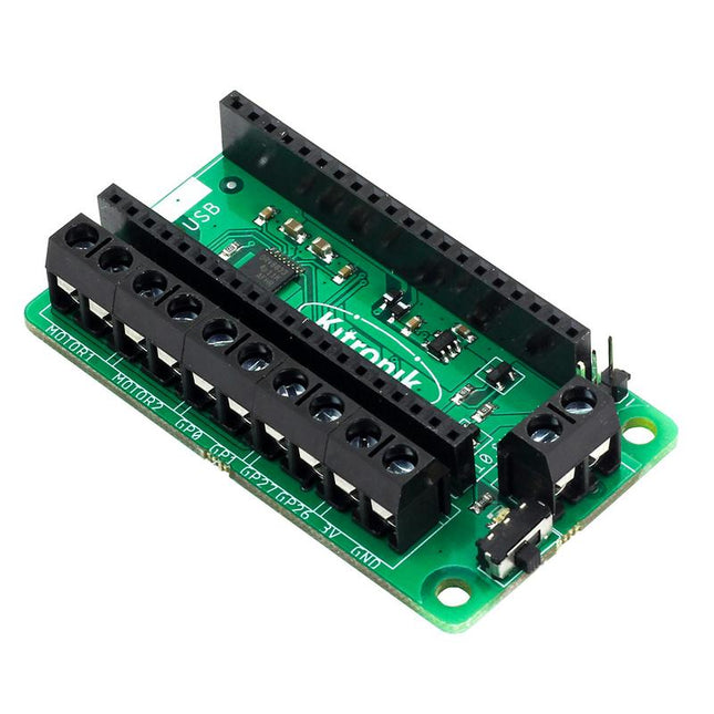
This board allows the Raspberry Pi Pico (connected via pin header) to drive two motors simultaneously with full forward, reverse & stop control, making it ideal for Pico controlled buggy projects. Alternatively, the board can be used to power a stepper motor. The board features the DRV8833 motor driver IC, which has built-in short circuit, over current and thermal protection. The board has 4 external connections to GPIO pins and a 3 V and GND supply from the Pico. This allows for additional IO options for your buggy builds that can be read or controlled by the Pico. In addition there is an on/off switch and power status LED, allowing you to see at a glance if the board is powered up and save your batteries when your project is not in use. To use the motor driver board, the Pico should have a soldered pin header and be inserted firmly into the connector. The board produces a regulated supply that is fed into the 40-way connector to power the Pico, removing the need to power the Pico directly. The motor driver board is powered via either screw terminals or a servo style connector. Kitronik has developed a micro-python module and sample code to support the use of the Motor Driver board with the Pico. This code is available in the GitHub repo. Features A compact yet feature-packed board designed to sit at the heart of your Raspberry Pi Pico robot buggy projects. The board can drive 2 motors simultaneously with full forward, reverse, and stop control. It features the DRV8833 motor driver IC, which has built-in short circuit, over current and thermal protection. Additionally, the board features an on/off switch and power status LED. Power the board via a terminal block style connector. The 3V and GND pins are also broken out, allowing external devices to be powered. Code it with MicroPython via an editor such as the Thonny editor. Dimensions: 63 mm (L) x 35 mm (W) x 11.6 mm (H) Download Datasheet
SD card quality is crucial for a good Raspberry Pi experience. Raspberry Pi's A2 microSD cards support higher bus speeds and command queuing, improving random read performance and narrowing the gap with NVMe SSDs. These cards are rigorously tested for optimal performance with Raspberry Pi models.
Features
Capacity: 64 GB
Support for DDR50 and SDR104 bus speeds and command queueing (CQ) extension
Speed Class: C10, U3, V30, A2
Random 4 KB read performance: 3,200 IOPS (Raspberry Pi 4, DDR50) 5,000 IOPS (Raspberry Pi 5, SDR104)
Random 4 K write performance: 1,200 IOPS (Raspberry Pi 4, DDR50) 2,000 IOPS (Raspberry Pi 5, SDR104)
Shock-proof, X-ray–proof, and magnet-proof
microSDHC/microSDXC formats
Downloads
Datasheets
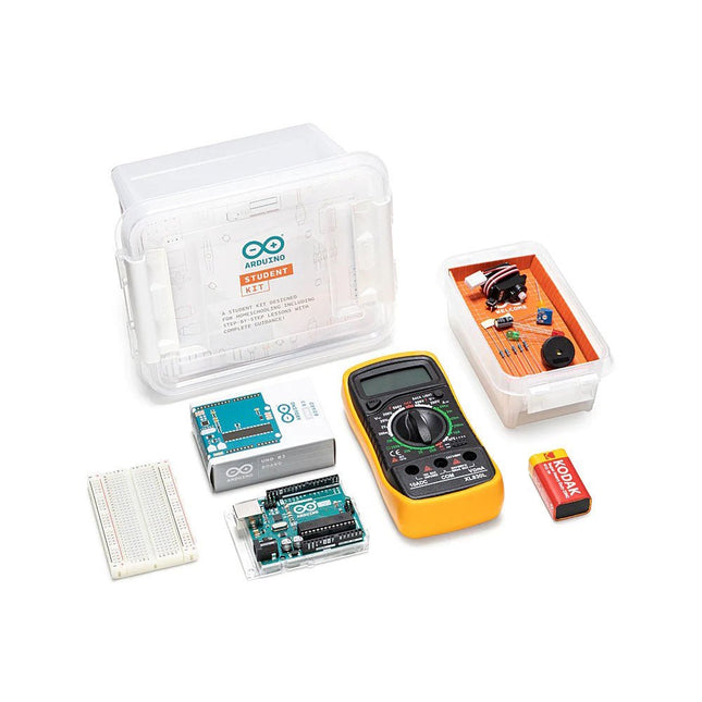
The Arduino Student Kit is a hands-on, step-by-step remote learning tool for ages 11+: get started with the basics of electronics, programming, and coding at home. No prior knowledge or experience is necessary as the kit guides you through step by step. Educators can teach their class remotely using the kits, and parents can use the kit as a homeschool tool for their child to learn at their own pace. Everyone will gain confidence in programming and electronics with guided lessons and open experimentation.
Learn the basics of programming, coding and electronics including current, voltage, and digital logic. No prior knowledge or experience is necessary as the kit guides you through step by step.
You’ll get all the hardware and software you need for one person, making it ideal to use for remote teaching, homeschooling, and for self-learning. There are step-by-step lessons, exercises, and for a complete and in-depth experience, there’s also extra content including invention spotlights, concepts, and interesting facts about electronics, technology, and programming.
Lessons and projects can be paced according to individual abilities, allowing them to learn from home at their own level. The kit can also be integrated into different subjects such as physics, chemistry, and even history. In fact, there’s enough content for an entire semester.
How educators can use the kit for remote teaching
The online platform contains all the content you need to teach remotely: exclusive learning guidance content, tips for remote learning, nine 90-minute lessons, and two open-ended projects. Each lesson builds off the previous one, providing a further opportunity to apply the skills and concepts students have already learned. They also get a logbook to complete as they work through the lessons.
The beginning of each lesson provides an overview, estimated completion times, and learning objectives. Throughout each lesson, there are tips and information that will help to make the learning experience easier. Key answers and extension ideas are also provided.
How the kit helps parents homeschool their children
This is your hands-on, step-by-step remote learning tool that will help your child learn the basics of programming, coding, and electronics at home. As a parent, you don’t need any prior knowledge or experience as you are guided through step-by-step. The kit is linked directly into the curriculum so you can be confident that your children are learning what they should be, and it provides the opportunity for them to become confident in programming and electronics. You’ll also be helping them learn vital skills such as critical thinking and problem-solving.
Self-learning with the Arduino Student Kit
Students can use this kit to teach themselves the basics of electronics, programming, and coding. As all the lessons follow step-by-step instructions, it’s easy for them to work their way through and learn on their own. They can work at their own pace, have fun with all the real-world projects, and increase their confidence as they go. They don’t need any previous knowledge as everything is clearly explained, coding is pre-written, and there’s a vocabulary of concepts to refer to.
The Arduino Student Kit comes with several parts and components that will be used to build circuits while completing the lessons and projects throughout the course.
Included in the kit
Access code to exclusive online content including learning guidance notes, step-by-step lessons and extra materials such as resources, invention spotlights and a digital logbook with solutions.
1x Arduino Uno
1x USB cable
1x Board mounting base
1x Multimeter
1x 9 V battery snap
1x 9 V battery
20x LEDs (5x red, 5x green, 5x yellow & 5x blue )
5x Resistors 560 Ω
5x Resistors 220 Ω
1x Breadboard 400 points
1x Resistor 1 kΩ
1x Resistor 10 kΩ
1x Small Servo motor
2x Potentiometers 10 kΩ
2x Knob potentiometers
2x Capacitors 100 uF
Solid core jumper wires
5x Pushbuttons
1x Phototransistor
2x Resistors 4.7 kΩ
1x Jumper wire black
1x Jumper wire red
1x Temperature sensor
1x Piezo
1x Jumper wire female to male red
1x Jumper wire female to male black
3x Nuts and Bolts
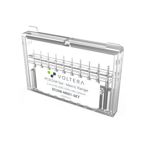
A set of high precision drill bits, covering the most common drill bit sizes.
Just pop them in the V-One Drill with a 2.5 mm hex key (not included) and start drilling.
The following sizes are included (2 of each):
0.70 mm
0.80 mm
0.90 mm
1.00 mm
1.60 mm
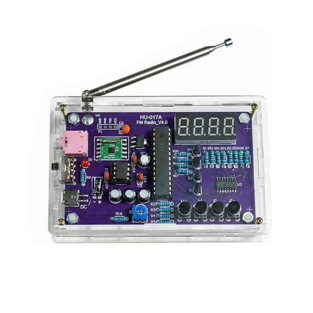
This DIY kit (HU-017A) is a wireless FM radio receiver with a 4-digit 7-segment display. It operates within the global FM receiving frequency band of 87.0-108.0 MHz, making it suitable for use in any country or region. The kit offers two power supply modes, allowing you to use it both at home and outdoors. This DIY electronic product will help you understand circuits and improve your soldering skills.
Features
87.0-108.0 MHz FM Radio: Built-in RDA5807 FM data processor with a standard FM receiving frequency band. The FM frequency can be adjusted using the F+ and F- buttons.
Adjustable Volume: Two volume adjustment methods – button and potentiometer. There are 15 volume levels.
Active & Passive Audio Output: The kit has a built-in 0.5 W power amplifier to drive 8 Ω speakers directly. It also outputs audio signals to headsets or loudspeakers with AUX interfaces, allowing personal listening and sharing of FM audio.
Configured with a 25 cm dedicated FM antenna and a (red) 4-digit 7-segment display for real-time display of FM radio frequency. The transparent acrylic shell protects the internal circuit board. It supports dual power supply methods – 5 V USB and 2x 1.5 V (AA) batteries.
DIY Hand Soldering: The kit comes with various components that need to be installed manually. It helps exercise and improve soldering skills, making it suitable for electronics hobbyists, beginners, and educational purposes.
Specifications
Operating voltage
DC 3 V/5 V
Output impedance
8 Ω
Output power
0.5 W
Output channel
Mono
Receiver frequency
87.0 MHz~108.0 MHz
Frequency accuracy
0.1 MHz
Operating temperature
−40°C to +85°C
Operating humidity
5% to 95% RH
Dimensions
107 x 70 x 23 mm
IMPORTANT: Remove the batteries when powering the radio over to USB.
Included
1x PCB
1x RDA5807M FM Receiver
1x STC15W404AS MCU
1x IC Socket
1x 74HC595D Register
1x TDA2822M Amplifier
1x IC Socket
1x AMS1117-3.3 V Voltage Converter
18x Metal Film Resistor
1x Potentiometer
4x Ceramic Capacitor
5x Electrolytic Capacitor
4x S8550 Transistor
1x Red LED
1x 4-digit 7-segment Display
1x Toggle Switch
1x SMD Micro USB Socket
1x Radio Antenna
1x AUX Audio Socket
4x Black Button
4x Button Cap
1x 0.5 W/8 Ω Speaker
1x Red/Black Wire
2x Double-sided adhesive
1x AA Battery Box
1x USB cable
6x Acrylic Board
4x Nylon Column Screw
4x M3 Screw
4x M3 Nut
4x M2x22 mm Screw
1x M2x6 mm Screw
5x M2 Nut
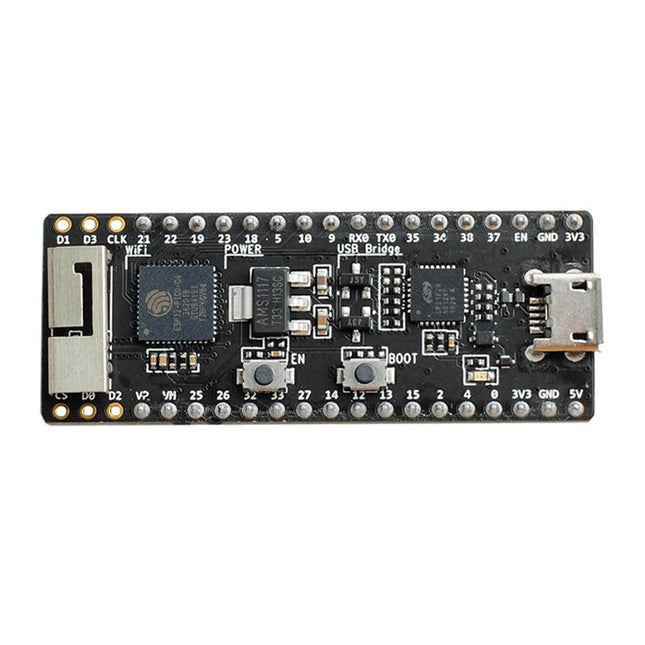
The ESP32-PICO-Kit fits into a mini breadboard. It is fully functional with the minimum number of discrete components, while it has all the ESP32 pins exposed.
Features
Complete up-to-date documentation is available.
All instructions and commands presented work as described.
Plentiful additional information and hardware documentation are available too.
Applications for the ESP32-PICO-KIT can be developed on Windows, Linux or Mac.
Two cores and a radio
Like the ESP8266 the ESP32 has Wi-Fi but adds Bluetooth. It also has two 32-bit cores inside, making it extremely powerful, and providing all the ports and interfaces that the ESP8266 is lacking.Oversimplifying things, one might say that the ESP8266 is a Wi-Fi controller that provides some I/O, whereas the ESP32 is a full-fledged controller that also has Wi-Fi.
ESP32 peripherals
The ESP32 exposes an ADC & DAC, touch sensor circuitry, an SD/SDIO/MMC host controller, an SDIO/SPI slave controller, an EMAC, PWM to control LEDs and motors, UART, SPI, I²C, I²S, infrared remote controller, and, of course, GPIO.
ESP32-PICO-KIT Development board
The ESP32-PICO-D4 is a System-on-Chip (SoC) integrating an ESP32 chip together with a 4 MB SPI flash memory in a tiny 7 x 7 mm package.
The ESP32-PICO-KIT is a breakout board for this SoC with an onboard USB-to-serial converter for easy programming and debugging.
Besides the board, you'll need a programming toolchain. Complete, up-to-date documentation from Espressif is available on the Read the Docs website.
All instructions and commands presented work as described.Plentiful additional information and hardware documentation are available too.
Applications for the ESP32-PICO-KIT can be developed on Windows, Linux or Mac.
,
by Lobna Belarbi
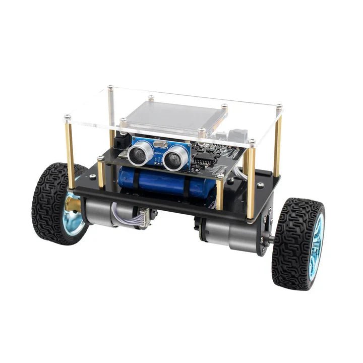
Affordable Robot Kits to Kickstart Your Robotics Journey
Robotics is an exciting and rewarding field, but getting started can be intimidating—especially when it comes to choosing the right kit. Fortunately, Elektor offers a...
,
by Lobna Belarbi
Must-Have Boards, Kits & Tools to Start Your Arduino Journey with Elektor
Whether you're a newcomer eager to explore the world of microcontrollers or an experienced maker seeking to expand your toolkit, Elektor offers a curated selection...