Search results for "high OR end OR mit OR roehren"
-

Elektor Digital High-End Valve Amplifiers 2 (E-book)
Nobody has any doubt that valve amplifiers produce a remarkably beautiful sound. They have a lively, deep, clear, and expressive sound, and dynamically they do not appear to have any limitations. The author investigates, in a systematic theoretical approach, the reasons for these beautiful properties. He develops new models for power valves and transformers, thus enabling the designer to determine the properties of the amplifier during the design process. Mathematical models for the coupling of power valve(s) and output transformer are provided. These will generate new insights in a special kind of distortion: the dynamic damping factor distortion (DDFD). With mathematical models in the complex domain, especially the properties at the limits of our hearing range (from 20 Hz to 20 kHz) are investigated and the minimal stability criteria for the amplifier are formulated. The often-applied negative feedback in amplifiers is extensively modelled and discussed in relation to our hearing appreciating. And after all this theory a fine selection of special amplifiers is presented and discussed. You will notice in this book that the author not only writes about amplifier technique, but tells about the way the development of valve amplifiers can have an influence on your daily life; even the usefulness of patents is discussed. Summarizing: new theories and solutions for perfect audio with valve amplifiers. Not only the professional and the DIY-er but everyone who wants to understand valve amplifiers will read this book with much pleasure.
€ 34,95
Members € 27,96
-

High-End Tube Amplifier Design
A Toolbox for Audio Lovers and Engineers Without any ambition to reach scientific levels, this book aims to be a toolbox for both audio lovers and high-end equipment designers. The elementary theory presented is the bare minimum for readers to grasp the operation and practical use of electrical, electromagnetic, physics, and electronic operations available in the designers’ toolbox. Each tool is explained in a minimum of words and theory without needless coverage of underlying equations or figures. The book chapters guide you through the process of designing quality amplifiers with vacuum tubes, from the very beginning, considering both technical and subjective requirements – in theory and practice. The book is a compilation of the author’s notes used in his professional and educational career but was nevertheless primarily written as a result of true love for the audiophile hobby.
€ 69,95
Members € 62,96
-

Elektor Digital High-End Tube Amplifier Design (E-book)
A Toolbox for Audio Lovers and Engineers Without any ambition to reach scientific levels, this book aims to be a toolbox for both audio lovers and high-end equipment designers. The elementary theory presented is the bare minimum for readers to grasp the operation and practical use of electrical, electromagnetic, physics, and electronic operations available in the designers’ toolbox. Each tool is explained in a minimum of words and theory without needless coverage of underlying equations or figures. The book chapters guide you through the process of designing quality amplifiers with vacuum tubes, from the very beginning, considering both technical and subjective requirements – in theory and practice. The book is a compilation of the author’s notes used in his professional and educational career but was nevertheless primarily written as a result of true love for the audiophile hobby.
€ 54,95
Members € 43,96
-

Elektor Digital Modern High-End Valve Amplifiers (E-book)
Valve Amplifiers are regarded by many to be the ne plus ultra when it comes to processing audio signals. The combination of classical technology and modern components has resulted in a revival of the valve amplifier. The use of toraidal-core output transformers, developed by the author over the past 15 years, has contributed to this revival. The most remarkable features of these transformers are their extremely wide frequency ranges and their very low levels of linear and nonlinear distortion. This book explains the whys and wherefores of toroidal output transformers at various technical levels, starting with elementary concepts and culminating in complete mathematical descriptions. In all of this, the interactions of the output valves, transformer and loudspeaker form the central theme. Next come the practical aspects. The schematic diagram of a valve amplifier often appears to be very simple at first glance, but anyone who has built a modern valve amplifier knows that a lot of critical details are hidden behind this apparent simplicity. These are discussed extensively, in connection with designs for amplifiers with output powers ranging from 10 to 100 watts. Finally, the author gives some attention to a number of special valve amplifiers, and to the theory and practice of negative feedback. In summary, this book offers innovative solutions for achieving perfect audio quality. Do-it-yourself builders, as well as persons who want to gain a deeper technical understanding of the complex world of audio transformers, valve amplifiers and audio signal processing, will find this book a rich and useful source of information.
€ 34,95
Members € 27,96
-

Elektor Digital MIT App Inventor Projects (E-book)
50+ Android Apps with Raspberry Pi, ESP32 and Arduino This book is about developing apps for Android compatible mobile devices using the MIT App Inventor online development environment. MIT App Inventor projects can be in either standalone mode or use an external processor. In standalone mode, the developed application runs only on the mobile device (e.g. Android). In external processor-based applications, the mobile device communicates with an external microcontroller-based processor, such as Raspberry Pi, Arduino, ESP8266, ESP32, etc. In this book, many tested and fully working projects are given both in standalone mode and using an external processor. Full design steps, block programs, circuit diagrams, QR codes and full program listings are given for all projects. The projects developed in this book include: Using the text-to-speech component Intonating a received SMS message Sending SMS messages Making telephone calls using a contacts list Using the GPS and Pin-pointing our location on a map Speech recognition and speech translation to another language Controlling multiple relays by speech commands Projects for the Raspberry Pi, ESP32 and Arduino using Bluetooth and Wi-Fi MIT APP Inventor and Node-RED projects for the Raspberry Pi The book is unique in that it is currently the only book that teaches how to develop projects using Wi-Fi and Node-RED with MIT App Inventor. The book is aimed at students, hobbyists, and anyone interested in developing apps for mobile devices. All projects presented in this book have been developed using the MIT App Inventor visual programming language. There is no need to write any text-based programs. All projects are compatible with Android-based mobile devices. Full program listings for all projects as well as detailed program descriptions are given in the book. Users should be able to use the projects as they are presented, modifying them to suit their own needs.
€ 32,95
Members € 26,36
-

Elektor Digital Building a High-Tech Alarm System with Raspberry Pi (E-book)
This book discusses the basic components of any alarm system. All alarm systems have two basic functions. First, they monitor their environment looking for a change such as a door or window opening or someone moving about in the room. Second, they alert the legal owner or user to this change. The system described in this book uses a scanning type software to detect intruders. It behaves like a guard dog, pacing up and down the fence line on the lookout for either an intruder or a familiar person. If you have an alarm key, you can disarm the system and enter. With the scanning method, the software is easy to write and explain. It can scan eight alarm zones plus two special fire zones in about one second. You don’t have to be an electrical engineer to install an alarm system, just a decent carpenter, painter, and plasterer! Because this alarm system runs on 12 volts, you don’t have to be a licensed electrician either to install it. The alarm system presented here uses Python software on the Raspberry Pi combined with some elementary electronic circuits. The code described in the book, as well as CAD files and a bill of materials for the alarm panel, are available for free downloading. The book provides the reader with examples of typical configurations coming straight from the author‘s experience. After reviewing the hardware components typically used in common alarm systems, the author shows how to plan one yourself. To implement a modular alarm, no matter if it is for a single house or for a business or restaurant, the book shows how to skillfully combine a Raspberry Pi with small auxiliary electronic circuits. These are not installation instructions but food for thought that will enable readers to find a solution to their needs.
€ 24,95
Members € 19,96
-

Loomia Loomia Single Backlit Button
The single backlit button is a simple mechanical switch that comes with an LED inside. When you press the button, the circuit is completed, driving your pin high or low. Use the embedded LED to make a glowing power icon, logo , or whatever suits your fancy. Features Press durability: Up to 10,000 times pressing under 5lbf (22.24 N) LED Voltage: 5 V Component: 2" x 3" Individual (5,08 x 7,62 cm) Button Size: 1" radius circle (2,54 cm)
€ 49,95€ 19,98
Members identical
-

Elektor Digital Experiments with Digital Electronics (E-book)
The field of digital electronics is central to modern technology. This e-book presents fundamental circuits using gates, flip-flops and counters from the CMOS 4000 Series. Each of the 50 experiments has a circuit diagram as well as a detailed illustration of the circuit’s construction on solderless breadboard. Learning these fundamentals is best done using practical experiments. Building these digital circuits will improve your knowledge and will be fun to boot. Many of the circuits presented here have practical real-life applications. With a good overview of the field, you’ll be well equipped to find simple and cost-effective solutions for any application. The e-book is targeted essentially at students, trainees and anyone with an interest in and requiring an introduction to digital control electronics. Moreover, the knowledge gleaned here is the foundation for further projects in the field of microcontrollers and programming.
€ 24,95
Members € 19,96
-

Loomia Loomia Double Backlit User Interface
Double Backlit User Interface: The dual backlit button is just like the single backlit button, but twice the fun! Use this component when you need to operate something up and down, or right to left. Using cut-out vinyl, you can create icons and stickers on fabric that show your users button functionality. Features Component: 4.6 x 6.3" Individual Button Size: 1" radius circle Press Durability: Up to 10,000 presses under 5lbf LED Voltage: 5 V
€ 54,95€ 21,98
Members identical
-

FNIRSI FNIRSI FNB58 USB Tester (with Bluetooth)
The FNIRSI FNB58 USB tester (with Bluetooth) is a comprehensive and very accurate USB voltage and current meter. It features a 2.0-inch full-color HD TFT display, built-in USB-A, micro USB and USB-C interface. With this device you can measure the power supply or power consumption of products or the charging power of cell phones and power supplies. You can also determine the fast charging protocol of chargers. Features USB-A and USB-C interface 2.0" HD display Data at a glance Wide compatibility Ultra-precise data detection Play with fast charging technology Automatic protocol detection (PD2.0, 3.0, 3.1, PPS, QC2.0, 3.0, FCP, SCP, AFC, PE, DASH VOOC, SuperVOOC and more) Simple user interface, easy to operate 4 function curve displays (real-time voltage and current curve, offline curve recording, D+/D- voltage curve, high-speed power supply ripple measurement) Cable detection 10 groups of energy recording battery capacity calculation PC connectivity for data logging and firmware updates Bluetooth app for Android devices Specifications Voltage range 4-28 V Current range 0-7 A Power range 0-120 W Load equivalent internal resistance 0-9999.9 Ω D+/D- voltage 0-3.3 V Capacity 0-9999.99 Ah Power consumption 0-9999.99 Wh Cable resistance 0-9999.9 Ω Interfaces micro USB, USB-A, USB-C Dimensions 42 x 13 x 82 mm Downloads Manual Firmware V0.68
€ 49,95


-

, by Lobna Belarbi Kickstart Your Electronics Journey with Elektor’s Learning Collection
Whether you're new to electronics or aiming to level up your embedded skills, Elektor’s Learning Collection delivers expert-curated kits, courses, and hands-on bundles. The first...
-
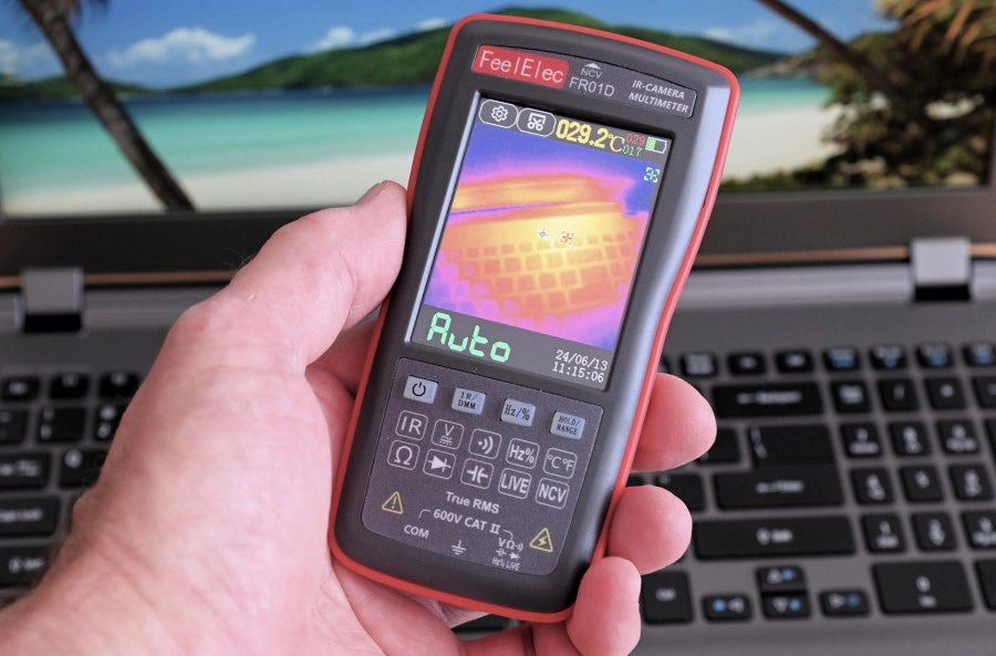
, by Harry Baggen FeelElec FR01D Multimeter With Thermal Imaging Camera (Review)
Chinese manufacturers of measuring equipment continue to surprise us with affordable measuring combinations that we would not have thought possible a few years ago. My...

