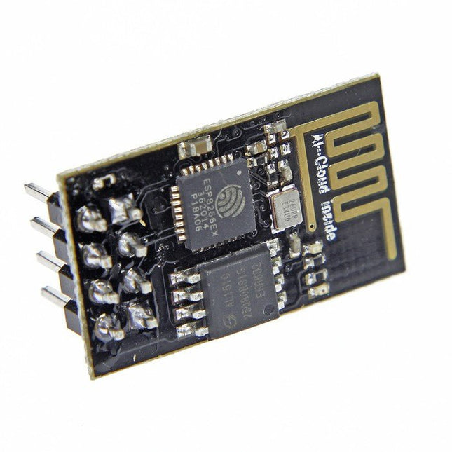
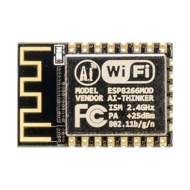
The ESP8266 is an impressive, low cost WiFi module suitable for adding WiFi functionality to an existing microcontroller project via a UART serial connection. The module can even be reprogrammed to act as a standalone WiFi connected device – just add power!
802.11 b/g/n protocol
Wi-Fi Direct (P2P), soft-AP
Integrated TCP/IP protocol stack
This module is a self-contained SOC (System On a Chip) that doesn’t necessarily need a microcontroller to manipulate inputs and outputs as you would normally do with an Arduino, for example, because the ESP-01 acts as a small computer. Thus, you can give a microcontroller internet access like the Wi-Fi shield does to the Arduino, or you can simply program the ESP8266 to not only have access to a Wi-Fi network, but to act as a microcontroller as well, which makes the ESP8266 very versatile.
Functionality, structure and handling of a power module
For readers with first steps in power management the “Abc of Power Modules” contains the basic principles necessary for the selection and use of a power module. The book describes the technical relationships and parameters related to power modules and the basis for calculation and measurement techniques.
Contents
Basics
This chapter describes the need of a DC/DC voltage converter and its basic functionality. Furthermore, various possibilities for realizing a voltage regulator are presented and the essential advantages of a power module are mentioned.
Circuit topologies
Circuit concepts, buck and boost topologies very frequently used with power modules are explained in detail and further circuit topologies are introduced.
Technology, construction and regulation technology
The mechanical construction of a power module is presented, which has a significant influence on EMC and thermal performance. Furthermore, control methods are explained and circuit design tips are provided in this chapter.
Measuring methods
Meaningful measurement results are absolutely necessary to assess a power module. The relevant measurement points and measurement methods are described in this chapter.
Handling
The aspects of storage and handling of power modules are explained, as well as their manufacturing and soldering processes.
Selection of a power modules
Important parameters and criteria for the optimal selection of a power module are presented in this section.
Maker Line is a line sensor with 5 x IR sensors array that is able to track line from 13 mm to 30 mm width.
The sensor calibration is also simplified. There is no need to adjust the potentiometer for each IR sensor. You just have to press the calibrate button for 2 seconds to enter calibration mode. Afterwards you need to sweep the sensors array across the line, press the button again and you are good to go.
The calibration data is saved in EEPROM and it will stay intact even if the sensor has been powered off. Thus, calibration only needs to be carried out once unless the sensor height, line color or background color has changed.
Maker Line also supports dual outputs: 5 x digital outputs for the state of each sensor independently, which is similar to conventional IR sensor, but you get the benefit of easy calibration, and also one analog output, where its voltage represents the line position. Analog output also offers higher resolution compared to individual digital outputs. This is especially useful when high accuracy is required while building a line following robot with PID control.
Features
Operating Voltage: DC 3.3 V and 5 V compatible (with reverse polarity protection)
Recommended Line Width: 13 mm to 30 mm
Selectable line color (light or dark)
Sensing Distance (Height): 4 mm to 40 mm (Vcc = 5 V, Black line on white surface)
Sensor Refresh Rate: 200 Hz
Easy calibration process
Dual Output Types: 5 x digital outputs represent each IR sensor state, 1 x analog output represents line position.
Support wide range of controllers such as Arduino, Raspberry Pi etc.
Downloads
Datasheet
Tutorial: Building A Low-Cost Line Following Robot
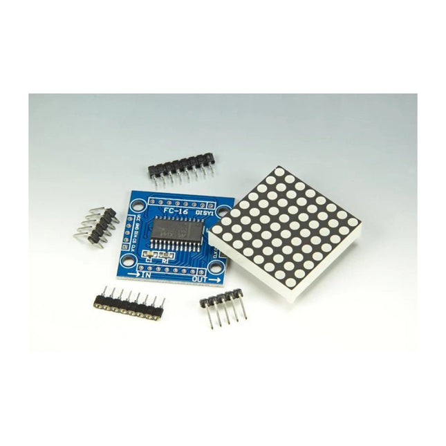
Scrolling text display with eight 8 x 8 LED dot matrix displays (512 LEDs in total). Built around an ESP-12F Wi-Fi module (ESP8266-based) programmed in the Arduino IDE. ESP8266 web server allows control of displayed text, scroll delay and brightness with a mobile phone or other Wi-Fi-connected (portable) device. Features 10 MHz Serial Interface Individual LED Segment Control Decode/No-Decode Digit Selection 150 µA Low-Power Shutdown (Data Retained) Digital and Analog Brightness Control Display Blanked on Power-Up Drive Common-Cathode LED Display Slew-Rate Limited Segment Drivers for Lower EMI (MAX7221) SPI, QSPI, MICROWIRE Serial Interface (MAX7221) 24-Pin DIP and SO Packages
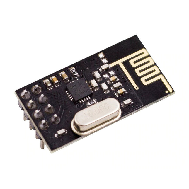
NRF24L01 is a universal ISM band monolithic transceiver chip works in the 2.4-2.5 GHz.
Features
Wireless transceiver including: Frequency generator, enhanced type, SchockBurstTM, mode controller, power amplifier, crystal amplifier, modulator, demodulator
The output power channel selection and protocol settings can be set extremely low current consumption, through the SPI interface
As the transmit mode, the transmit power is 6 dBm, the current is 9.0 mA, the accepted mode current is 12.3 mA, the current consumption of the power-down mode and standby mode are lower
Built-in 2.4 GHz antenna, supports up to six channels of data reception
Size: 15 x 29 mm (including antenna)
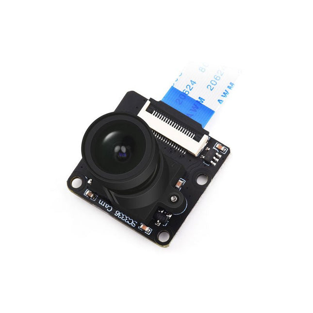
This camera module adopts a SmartSens SC3336 sensor chip with 3 MP resolution. It features high sensitivity, high SNR, and low light performance and it is capable of a more delicate and vivid night vision imaging effect, and can better adapt to ambient light changes. Also, it is compatible with Luckfox Pico series boards.
Specifications
Sensor
Sensor: SC3336
CMOS size: 1/2.8"
Pixels: 3 MP
Static resolution: 2304x1296
Maximum video frame rate: 30fps
Shutter: Rolling shutter
Lens
Focal length: 3.95 mm
Aperture: F2.0
FOV: 98.3° (diagonal)
Distortion: <33%
Focusing: Manual focus
Downloads
Wiki
The flexibility of the Artemis module starts with SparkFun's Arduino core. You can program and use the Artemis module just like you would an Uno or any other Arduino. The time to first blink is just 5 minutes away! We built the core from the ground up, making it fast and as lightweight as possible.
Next is the module itself. Measuring 10 x 15 mm, the Artemis module has all the support circuitry you need to use the fantastic Ambiq Apollo3 processor in your next project. We're proud to say the SparkFun Artemis module is the first open-source hardware module with the design files freely and easily available. We've carefully designed the module so that implementing Artemis into your design can be done with low-cost 2-layer PCBs and 8mil trace/space.
Made in the USA at SparkFun's Boulder production line, the Artemis module is designed for consumer-grade products. This truly differentiates the Artemis from its Arduino brethren. Ready to scale your product? The Artemis will grow with you beyond the Uno footprint and Arduino IDE. Additionally, the Artemis has an advanced HAL (hardware abstraction layer), allowing users to push the modern Cortex-M4F architecture to its limit.
The SparkFun Artemis Module is fully FCC/IC/CE certified and is available in full tape and reel quantities. With 1M flash and 384k RAM, you'll have plenty of room for your code. The Artemis module runs at 48MHz with a 96MHz turbo mode available and with Bluetooth to boot!
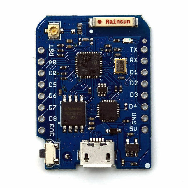
This Wi-Fi module is based on the popular ESP8266 chip. The module is FCC and CE certified and RoHS compliant.
Fully compatible with ESP-12E. 13 GPIO pins, 1 analog input, 4 MB flash memory.
Developing CoAP applications for Thread networks with Zephyr
This book will guide you through the operation of Thread, the setup of a Thread network, and the creation of your own Zephyr-based OpenThread applications to use it. You’ll acquire knowledge on:
The capture of network packets on Thread networks using Wireshark and the nRF Sniffer for 802.15.4.
Network simulation with the OpenThread Network Simulator.
Connecting a Thread network to a non-Thread network using a Thread Border Router.
The basics of Thread networking, including device roles and types, as well as the diverse types of unicast and multicast IPv6 addresses used in a Thread network.
The mechanisms behind network discovery, DNS queries, NAT64, and multicast addresses.
The process of joining a Thread network using network commissioning.
CoAP servers and clients and their OpenThread API.
Service registration and discovery.
Securing CoAP messages with DTLS, using a pre-shared key or X.509 certificates.
Investigating and optimizing a Thread device’s power consumption.
Once you‘ve set up a Thread network with some devices and tried connecting and disconnecting them, you’ll have gained a good insight into the functionality of a Thread network, including its self-healing capabilities. After you’ve experimented with all code examples in this book, you’ll also have gained useful programming experience using the OpenThread API and CoAP.
40+ Projects using Arduino, Raspberry Pi and ESP32
This book is about developing projects using the sensor-modules with Arduino Uno, Raspberry Pi and ESP32 microcontroller development systems. More than 40 different sensors types are used in various projects in the book. The book explains in simple terms and with tested and fully working example projects, how to use the sensors in your project. The projects provided in the book include the following:
Changing LED brightness
RGB LEDs
Creating rainbow colours
Magic wand
Silent door alarm
Dark sensor with relay
Secret key
Magic light cup
Decoding commercial IR handsets
Controlling TV channels with IT sensors
Target shooting detector
Shock time duration measurement
Ultrasonic reverse parking
Toggle lights by clapping hands
Playing melody
Measuring magnetic field strength
Joystick musical instrument
Line tracking
Displaying temperature
Temperature ON/OFF control
Mobile phone-based Wi-Fi projects
Mobile phone-based Bluetooth projects
Sending data to the Cloud
The projects have been organized with increasing levels of difficulty. Readers are encouraged to tackle the projects in the order given. A specially prepared sensor kit is available from Elektor. With the help of this hardware, it should be easy and fun to build the projects in this book.
The JOY-iT R301T fingerprint sensor module is capable of image collection and algorithm calculation due to this integrated chip. Another remarkable function of the sensor is, that it can recognize the fingerprint in different conditions, for example humidity, light texture or changes of the skin. This offers a very wide range of possible applications to secure locks and doors among others. The chip can send data via UART, TTL serial and USB to the connected controller.
Specifications
Model
JP2000 sensor
Chip
32 Bit ARM Cortex-M3
Chip storage
96 kB RAM, 1 MB Flash
Power supply
4.2-6.0 V
Working current
Typical: 40 mAPeak: 50 mA
Logic level
3,3/5 V TTL Logic
Fingerprint storage capacity
3000 Prints
Matching mode
1:N Identification1:1 Verification
Adjustable security level
1 - 5 levels(default security level: 3)
False acceptance rate
< 0.001%(on security level 3)
False acceptance rate
< 0.1%(on security level 3)
Response time
Pre-treatment: < 0.45 sMatch: < 1.5 s
Baud rate support
9600 - 921600
UART communication
No parity, Stop Bit: 1
Dimensions
42 x 19 x 8 mm
Included
1x Fingerprint sensor COM-FP-R301T
1x Cable
Downloads
Datasheet
Manual