50+ Android Apps with Raspberry Pi, ESP32 and Arduino
This book is about developing apps for Android compatible mobile devices using the MIT App Inventor online development environment. MIT App Inventor projects can be in either standalone mode or use an external processor. In standalone mode, the developed application runs only on the mobile device (e.g. Android). In external processor-based applications, the mobile device communicates with an external microcontroller-based processor, such as Raspberry Pi, Arduino, ESP8266, ESP32, etc.
In this book, many tested and fully working projects are given both in standalone mode and using an external processor. Full design steps, block programs, circuit diagrams, QR codes and full program listings are given for all projects.
The projects developed in this book include:
Using the text-to-speech component
Intonating a received SMS message
Sending SMS messages
Making telephone calls using a contacts list
Using the GPS and Pin-pointing our location on a map
Speech recognition and speech translation to another language
Controlling multiple relays by speech commands
Projects for the Raspberry Pi, ESP32 and Arduino using Bluetooth and Wi-Fi
MIT APP Inventor and Node-RED projects for the Raspberry Pi
The book is unique in that it is currently the only book that teaches how to develop projects using Wi-Fi and Node-RED with MIT App Inventor. The book is aimed at students, hobbyists, and anyone interested in developing apps for mobile devices.
All projects presented in this book have been developed using the MIT App Inventor visual programming language. There is no need to write any text-based programs. All projects are compatible with Android-based mobile devices. Full program listings for all projects as well as detailed program descriptions are given in the book. Users should be able to use the projects as they are presented, modifying them to suit their own needs.
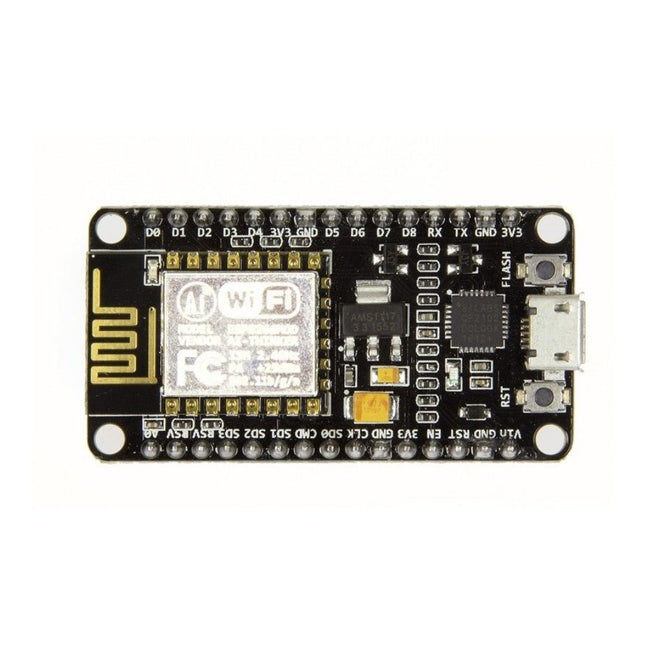
Note: NodeMCU is the name of both a firmware and a boardNodeMCU is an open source IoT platform, whose firmware runs on Espressif's SoC Wi-Fi ESP8266, based on the ESP8266 nonOS SDK. Its hardware is based on the ESP-12 module. The scripting language is Lua which allows to use many open source projects like lua-cjson and spiffs. Features Wi-Fi Module – ESP-12E module similar to ESP-12 module but with 6 extra GPIOs. USB – micro USB port for power, programming and debugging Headers – 2x 2.54 mm 15-pin header with access to GPIOs, SPI, UART, ADC, and power pins Reset & Flash buttons Power: 5V via micro USB port Dimensions: 49 x 24.5 x 13 mm
AVR Architecture and Programming An in-depth look at the 8-bit AVR architecture found in ATtiny and ATmega microcontrollers, mainly from a software and programming point of view. Explore the AVR architecture using C and assembly language in Microchip Studio (formerly Atmel Studio) with ATtiny microcontrollers. Learn the details of how AVR microcontrollers work internally, including the internal registers and memory map of ATtiny devices. Program ATtiny microcontrollers using an Atmel-ICE programmer/debugger, or use a cheap hobby programmer, or even an Arduino Uno as a programmer. Most code examples can be run using the Microchip Studio AVR simulator. Learn to write programs for ATtiny microcontrollers in assembly language. See how assembly language is converted to machine code instructions by the assembler program. Find out how programs written in the C programming language end up as assembly language and finally as machine code instructions. Use the Microchip Studio debugger in combination with a hardware USB programmer/debugger to test assembly and C language programs, or use the Microchip Studio AVR simulator. DIP packaged ATtiny microcontrollers are used in this volume for easy use on electronic breadboards, targeting mainly the ATtiny13(A) and ATtiny25/45/85. Learn about instruction timing and clocks in AVR microcontrollers using ATtiny devices. Be on your way to becoming an AVR expert with advanced debugging and programming skills.
Specifications Lens diameter: 90 mm / 3.54' Dioptre: lens Ø 90 mm: dioptre 3 – magnification: 1.75 Power supply: 3 x 1.5 V AAA battery Dimensions: 210 x 170 x 110 mm / 8.3 x 6.7 x 4.3' Weight: 615 g Material: Stand: stainless steel Lens: glass Connecting parts: copper
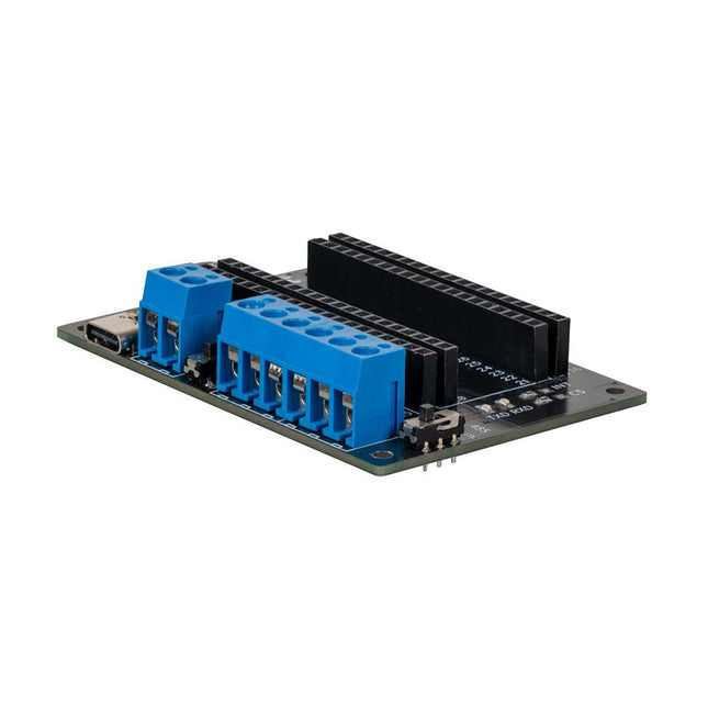
This expansion board allows you to add an RS485 and a CAN interface to a Raspberry Pi Pico.
The board also offers the option of operating it either via a standard USB-C connection with 5 V or via a screw terminal that accepts a voltage of 6 to 12 V. The voltage applied to the screw terminal is reduced to 5 V by a voltage converter integrated on the board.
Features
Power can be supplied via a USB-C connection with 5 V or via a screw terminal that draws between 6 and 12 V. In the latter case, a built-in voltage converter reduces the voltage to 5 V.
To increase the versatility and range of functions, the connection pins of the Raspberry Pi Pico have been routed to the outside.
The expansion board also offers the option of communication via the RS485 and CAN interfaces.
Specifications
CAN Interface
SPI, CAN
RS485 Interface
Serial, RS485
Power supply
5 V DC (USB-C)
Screw terminal
6-12 V DC
Logic level
3.3 V
Terminating resistor CAN
120 Ω (can be activated and deactivated as required)
Terminating resistor RS485
120 Ω (can be activated and deactivated as required)
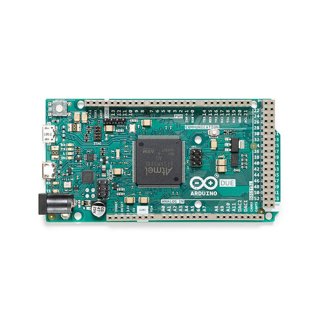
The board contains everything needed to support the microcontroller; simply connect it to a computer with a micro-USB cable or power it with an AC-to-DC adapter or battery to get started. The Due is compatible with all Arduino shields that work at 3.3V and are compliant with the 1.0 Arduino pinout.
The Due follows the 1.0 pinout:
TWI: SDA and SCL pins that are near to the AREF pin.
IOREF: allows an attached shield with the proper configuration to adapt to the voltage provided by the board. This enables shield compatibility with a 3.3V board like the Due and AVR-based boards which operate at 5V.
An unconnected pin, reserved for future use.
Specifications
Operating Voltage
3.3 V
Input Voltage
7-12 V
Digital I/O
54
Analog Input Pins
12
Analog Output Pins
2 (DAC)
Total DC Output Current on all I/O Lines
130 mA
DC Current per I/O Pin
20 mA
DC Current for 3.3 V Pin
800 mA
DC Current for 5 V Pin
800 mA
Flash Memory
512 KB all available for the user applications
SRAM
96 KB
Clock Speed
84 MHz
Length
101.52 mm
Width
53.3 mm
Weight
36 g
Please note: Unlike most Arduino boards, the Arduino Due board runs at 3.3V. The maximum voltage that the I/O pins can tolerate is 3.3V. Applying voltages higher than 3.3V to any I/O pin could damage the board.
The single backlit button is a simple mechanical switch that comes with an LED inside. When you press the button, the circuit is completed, driving your pin high or low. Use the embedded LED to make a glowing power icon, logo , or whatever suits your fancy.
Features
Press durability: Up to 10,000 times pressing under 5lbf (22.24 N)
LED Voltage: 5 V
Component: 2" x 3" Individual (5,08 x 7,62 cm)
Button Size: 1" radius circle (2,54 cm)
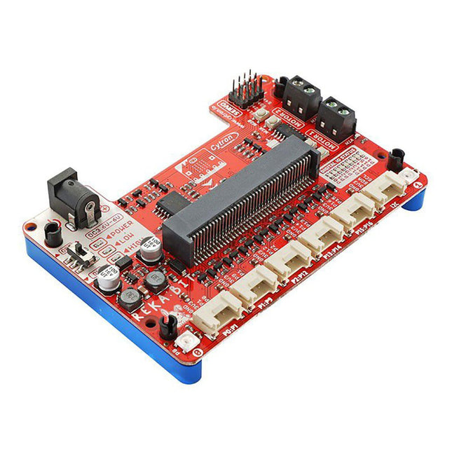
Program your REKA:BIT with Microsoft MakeCode Editor. Just add REKA:BIT MakeCode Extension and you’re good to go. If you’re a beginner, you can start with the block programming mode; simply drag, drop and snap the coding blocks together. For more advanced users, you can easily switch into JavaScript or Python mode on MakeCode Editor for text-based programming.
REKA:BIT possesses a lot of indicator LEDs to assist your coding and troubleshooting. It covers the IO pins connected to all six Grove ports and DC motor outputs from the co-processor. One is able to check his/her program and circuit connection easily by monitoring these LEDs.
Besides, REKA:BIT also has a power on/off indicator, undervoltage, and overvoltage LEDs built-in to give appropriate warnings should there be any problem with the power input.
REKA:BIT features a co-processor to handle multitasking more efficiently. Playing music while controlling up to 4x servo motors and 2x DC motors, animating micro:bit LED matrix, and even lighting up RGB LEDs in different colors, all at the same time, is not a problem for REKA:BIT.
Features
2x DC motor terminals
Built-in motor quick test buttons (no coding needed)
4x Servo motor ports
2x Neopixel RGB LEDs
6x Grove port (3.3 V)
3x Analog Input / Digital IO ports
2x Digital IO ports
1x I²C Interface
DC jack for power input (3.6-6 V DC)
ON/OFF switch
Power on indicator
Undervoltage (LOW) indicator & protection
Over-voltage (HIGH) indicator & protection
Dimensions: 10.4 x 72 x 15 mm
Included
1x REKA:BIT expansion board
1x USB power and data cable
1x 4xAA battery holder
1x Mini screwdriver
3x Grove to female header cable
2x Building block 1x9 lift arm
4x Building block friction pin
Please note: micro:bit board not included
M5Stamp Fly is a programmable open-source quadcopter, featuring the StampS3 as the main controller. It integrates a BMI270 6-axis gyroscope and a BMM150 3-axis magnetometer for attitude and direction detection. The BMP280 barometric pressure sensor and two VL53L3 distance sensors enable precise altitude hold and obstacle avoidance. The PMW3901MB-TXQT optical flow sensor provides displacement detection.
The kit includes a buzzer, a reset button, and WS2812 RGB LEDs for interaction and status indication. It is equipped with a 300 mAh high-voltage battery and four high-speed coreless motors. The PCB features an INA3221AIRGVR for real-time current/voltage monitoring and has two Grove connectors for additional sensors and peripherals.
Preloaded with debugging firmware, the Stamp Fly can be controlled using an Atom Joystick via the ESP-NOW protocol. Users can choose between automatic and manual modes, allowing for easy implementation of functions like precise hovering and flips. The firmware source code is open-source, making the product suitable for education, research, and various drone development projects.
Applications
Education
Research
Drone development
DIY projects
Features
M5StampS3 as the main controller
BMP280 for barometric pressure detection
VL53L3 distance sensors for altitude hold and obstacle avoidance
6-axis attitude sensor
3-axis magnetometer for direction detection
Optical flow detection for hovering and displacement detection
Buzzer
300 mAh high-voltage battery
Current and voltage detection
Grove connector expansion
Specifications
M5StampS3
ESP32-S3@Xtensa LX7, 8 MB Flash, WiFi, OTG\CDC support
Motor
716-17600kv
Distance Sensor
VL53L3CXV0DH/1 (0x52) @ max 3 m
Optical Flow Sensor
PMW3901MB-TXQT
Barometric Sensor
BMP280 (0x76) @ 300-1100hPa
3-axis Magnetometer
BMM150 (0x10)
6-axis IMU Sensor
BMI270
Grove
I²C+UART
Battery
300mAh 1S high-voltage lithium battery
Current/Voltage Detection
INA3221AIRGVR (0x40)
Buzzer
Built-in Passive Buzzer @ 5020
Operating temperature
0-40°C
Dimensions
81.5 x 81.5 x 31 mm
Weight
36.8 g
Included
1x Stamp Fly
1x 300 mAh high-voltage Lithium battery
Downloads
Documentation
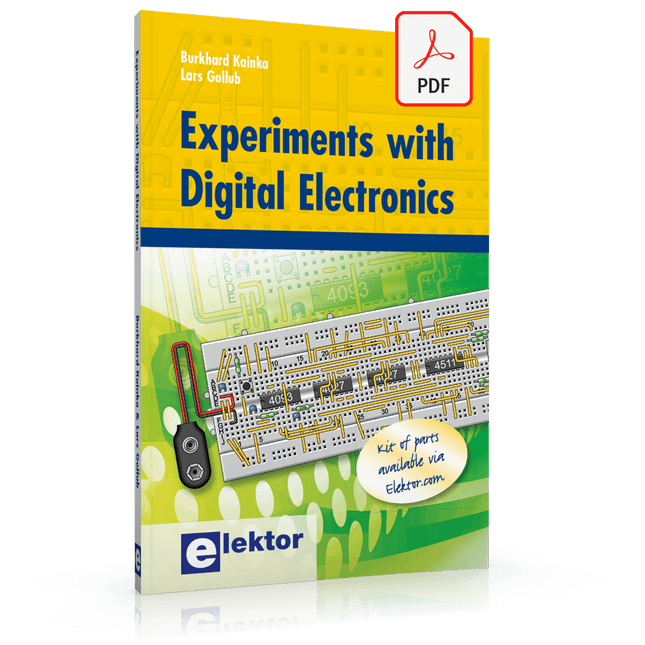
The field of digital electronics is central to modern technology. This e-book presents fundamental circuits using gates, flip-flops and counters from the CMOS 4000 Series. Each of the 50 experiments has a circuit diagram as well as a detailed illustration of the circuit’s construction on solderless breadboard.
Learning these fundamentals is best done using practical experiments. Building these digital circuits will improve your knowledge and will be fun to boot. Many of the circuits presented here have practical real-life applications. With a good overview of the field, you’ll be well equipped to find simple and cost-effective solutions for any application.
The e-book is targeted essentially at students, trainees and anyone with an interest in and requiring an introduction to digital control electronics. Moreover, the knowledge gleaned here is the foundation for further projects in the field of microcontrollers and programming.
,
by Lobna Belarbi
Kickstart Your Electronics Journey with Elektor’s Learning Collection
Whether you're new to electronics or aiming to level up your embedded skills, Elektor’s Learning Collection delivers expert-curated kits, courses, and hands-on bundles. The first...
,
by Harry Baggen
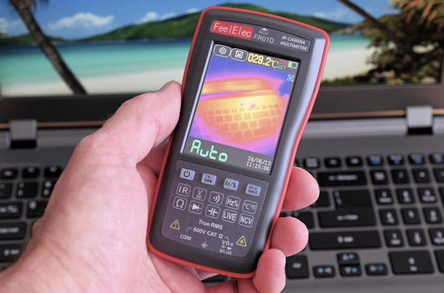
FeelElec FR01D Multimeter With Thermal Imaging Camera (Review)
Chinese manufacturers of measuring equipment continue to surprise us with affordable measuring combinations that we would not have thought possible a few years ago. My...