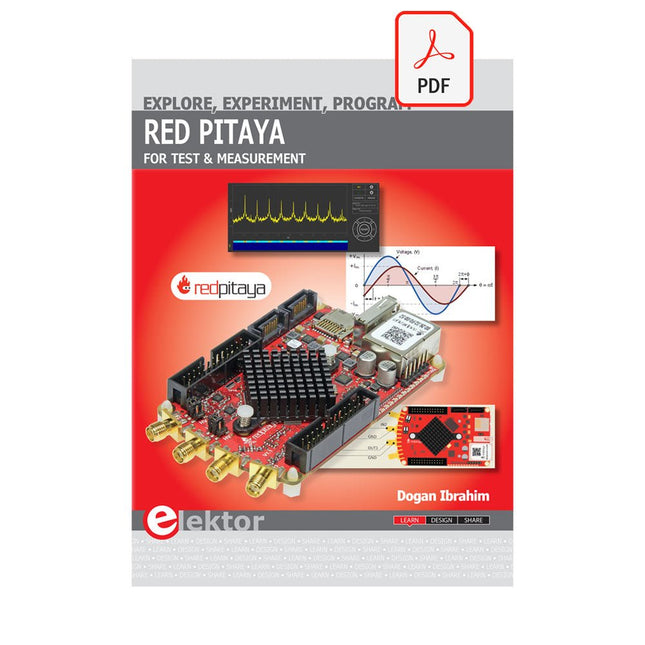
The Red Pitaya (STEMlab) is a credit card-sized, open-source test and measurement board that can be used to replace most measurement instruments used in electronics laboratories. With a single click, the board can transform into a web-based oscilloscope, spectrum analyser, signal generator, LCR meter, Bode plotter, and microcontroller.
The Red Pitaya (STEMlab) can replace the many pieces of expensive measurement equipment found at professional research organisations and teaching laboratories. The device, that based on Linux, includes an FPGA, digital signal processing (DSP), dual core ARM Cortex processor, signal acquisition and generation circuitry, micro USB socket, microSD card slot, RJ45 socket for Ethernet connection, and USB socket – all powered from an external mains adaptor.
This book is an introduction to electronics. It aims to teach the principles and applications of basic electronics by carrying out real experiments using the Red Pitaya (STEMlab). The book includes many chapters on basic electronics and teaches the theory and use of electronic components including resistors, capacitors, inductors, diodes, transistors, and operational amplifiers in electronic circuits. Many fun and interesting Red Pitaya (STEMlab) experiments are included in the book. The book also makes an introduction to visual programming environment.
The book is written for college level and first year university students studying electrical or electronic engineering.
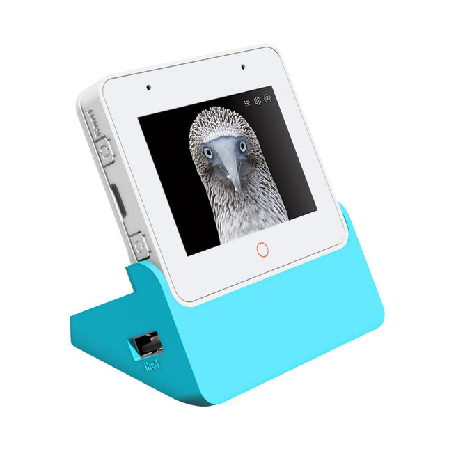
ESP32-S3-BOX-3 is based on Espressif’s ESP32-S3 Wi-Fi + Bluetooth 5 (LE) SoC, with AI acceleration capabilities. In addition to ESP32-S3’s 512 KB SRAM, ESP32-S3-BOX-3 comes with 16 MB of Quad flash and 16 MB of Octal PSRAM.
ESP32-S3-BOX-3 runs Espressif’s own speech-recognition framework, ESP-SR, which provides users with an offline AI voice-assistant. It features far-field voice interaction, continuous recognition, wake-up interruption, and the ability to recognize over 200 customizable command words. BOX-3 can also be transformed into an online AI chatbot using advanced AIGC development platforms, such as OpenAI.
Powered by the high-performance ESP32-S3 SoC, BOX-3 provides developers with an out-of-the-box solution to creating Edge AI and HMI applications. The advanced features and capabilities of BOX-3 make it an ideal choice for those in the IIoT industry who want to embrace Industry 4.0 and transform traditional factory-operating systems.
ESP32-S3-BOX-3 is the main unit powered by the ESP32-S3-WROOM-1 module, which offers 2.4 GHz Wi-Fi + Bluetooth 5 (LE) wireless capability as well as AI acceleration capabilities. On top of 512 KB SRAM provided by the ESP32-S3 SoC, the module comes with additional 16 MB Quad flash and 16 MB Octal PSRAM. The board is equipped a 2.4-inch 320 x 240 SPI touch screen (the ‘red circle’ supports touch), two digital microphones, a speaker, 3‑axis Gyroscope, 3‑axis Accelerometer, one Type-C port for power and download/debug, a high-density PCIe connector which allows for hardware extensibility, as well as three functional buttons.
Features
ESP32-S3
WiFi + Bluetooth 5 (LE)
Built-in 512 KB SRAM
ESP32-S3-WROOM-1
16 MB Quad flash
16 MB Octal PSRAM
Included
ESP32-S3-BOX-3 Unit
ESP32-S3-BOX-3 Sensor
ESP32-S3-BOX-3 Dock
ESP32-S3-BOX-3 Bracket
ESP32-S3-BOX-3 Bread
RGB LED module and Dupont wires
USB-C cable
Downloads
GitHub
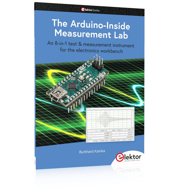
An 8-in-1 test & measurement instrument for the electronics workbench
A well-equipped electronics lab is crammed with power supplies, measuring devices, test equipment and signal generators. Wouldn‘t it be better to have one compact device for almost all tasks? Based on the Arduino, a PC interface is to be developed that’s as versatile as possible for measurement and control. It simply hangs on a USB cable and – depending on the software – forms the measuring head of a digital voltmeter or PC oscilloscope, a signal generator, an adjustable voltage source, a frequency counter, an ohmmeter, a capacitance meter, a characteristic curve recorder, and much more.
The circuits and methods collected here are not only relevant for exactly these tasks in the "MSR" electronics lab, but many details can also be used within completely different contexts.
Errata/Updates
In the programs printed, all instances of “be()” should read: sei().
Features
Synchronous mode: Auto, Normal, Single, None, Scan
Rising/Falling edge trigger
Modes of vertical precise, horizontal precise measurement and triggering threshold
Auto Measurement: frequency, cycle time, duty cycle, DC RMS voltage/Vpp /Vmax/Vmin/Vavg
Inbuilt signal generator/10 Hz-1 MHz square wave (duty adjustable) or 10 Hz-20 KHz
Sine/Square/Triangle/Sawtooth wave
Specifications
Analog bandwidth
1 MHz
Max sample rate
10 Msa/s
Max sample memory depth
8K
Analog input impedance
1 MΩ
Max input voltage
±40 V (X1)
Coupling
AC/DC
Vertical sensitivity
20 mv/Div~10 V/Div (1-2-5)
Horizontal sensitivity
1 uS/Div~2 S/Div (1-2-5)
Storage
Built-in 8 MB U disk storage for waveform data and images
Power supply
Internal 550 mAh Lithium battery, recharging through Micro USB port
Display
2.8' Full Color TFT LCD (320x240 pixels)
Dimensions
100 x 56.5 x 10.7 mm
Downloads
User Manual
Source Code
App
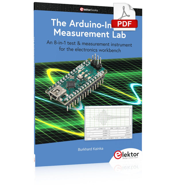
An 8-in-1 test & measurement instrument for the electronics workbench
A well-equipped electronics lab is crammed with power supplies, measuring devices, test equipment and signal generators. Wouldn‘t it be better to have one compact device for almost all tasks? Based on the Arduino, a PC interface is to be developed that’s as versatile as possible for measurement and control. It simply hangs on a USB cable and – depending on the software – forms the measuring head of a digital voltmeter or PC oscilloscope, a signal generator, an adjustable voltage source, a frequency counter, an ohmmeter, a capacitance meter, a characteristic curve recorder, and much more.
The circuits and methods collected here are not only relevant for exactly these tasks in the "MSR" electronics lab, but many details can also be used within completely different contexts.
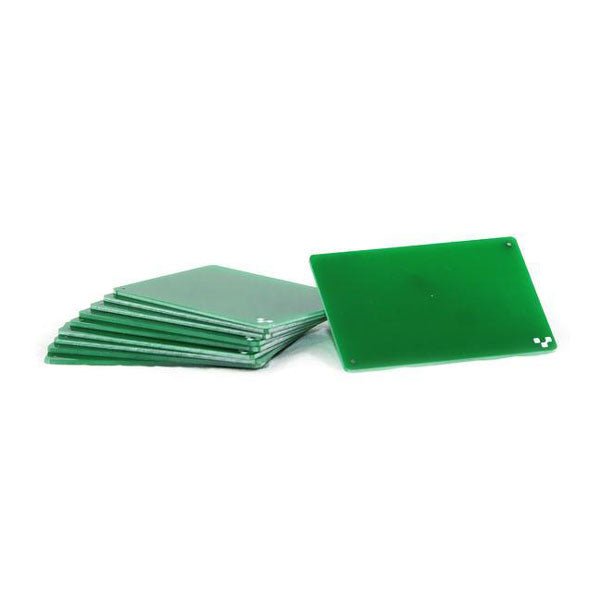
If you are going to be drilling, we recommend drilling on FR1 substrates. Unlike FR4, FR1 dust does not contain fiber glass. It is also a softer material, which means a less wear and tear on the drill bits. Download the template and incorporate them into your design here. 10 substrates included.
This book is intended as a highly-practical guide for Hobbyists, Engineers and Scientists wishing to build measurement and control systems to be controlled by a local or remote Personal Computer running the Linux operating system. Both hardware and software aspects of designing typical embedded systems are covered in detail with schematics, code listings and full descriptions. Numerous examples have been designed to show clearly how straightforward it can be to create the interfaces between digital and analog electronics, with programming techniques for creating control software for both local and remote systems. Hardware developers will appreciate the variety of circuits, including a novel, low cost modulated wireless link and will discover how using Matlab® overcomes the need for specialist programming skills.
Software developers will appreciate how a better understanding of circuits plus the freedom offered by Linux to directly control at the register level enables them to optimize related programs. There is no need to buy special equipment or expensive software tools in order to create embedded projects covered in this book. You can build such quality systems quickly using popular low-cost electronic components and free distributed or low-cost software tools. Some knowledge of basic electronics plus the very basics of C programming only is required.
Many projects in this book are developed using Matlab® being a very popular worldwide computational tool for research in engineering and science. The book provides a detailed description of how to combine the power of Matlab® with practical electronics.
With an emphasis on learning by doing, readers are encouraged by examples to program with ease; the book provides clear guidelines as to the appropriate programming techniques “on the fly”. Complete and well-documented source code is provided for all projects.
If you want to learn how to quickly build Linux-based applications able to collect, process and display data on a PC from various analog and digital sensors, how to control circuitry attached to a computer, then even how to pass data via a network or control your embedded system wirelessly and more – then this is the book for you!
Features of this Book
Use the power, flexibility and control offered only by a Linux operating system on a PC.
Use a free, distributed downloadable GNU C compiler Use (optional) a low-cost Student Version of Matlab®.
Use low-cost electronic sub-assemblies for projects.
Improve your skills in electronics, programming, networking and wireless design.
A full chapter is dedicated to controlling your sound card for audio input and output purposes.
Program sound using OSS and ALSA.
Learn how to combine electronic circuits, software, networks and wireless technologies in the complete embedded system.
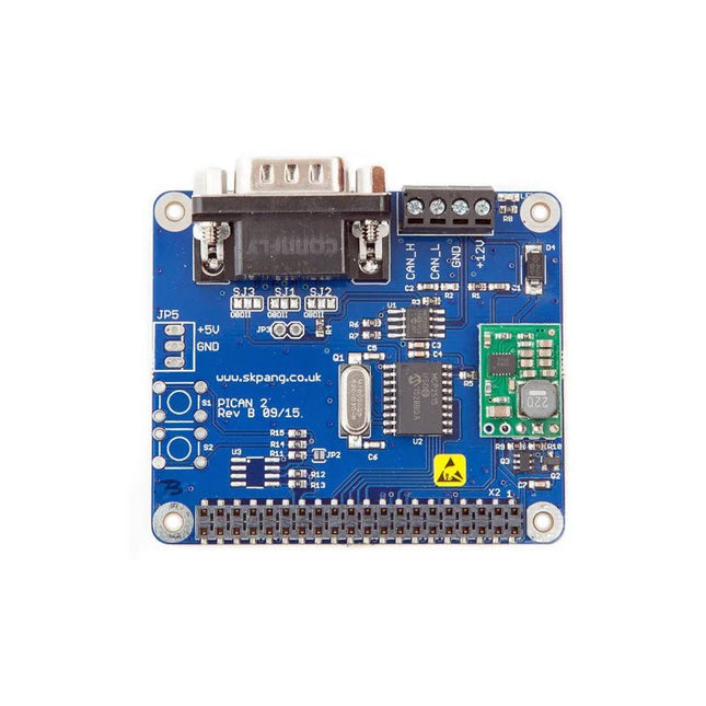
This PiCAN 2 board provides CAN-Bus capability for the Raspberry Pi 2/3. It uses the Microchip MCP2515 CAN controller with MCP2551 CAN transceiver. Connection are made via DB9 or 3-way screw terminal. This board includes a switch mode power suppler that powers the Raspberry Pi is well.
Easy to install SocketCAN driver. Programming can be done in C or Python.
Not suitable for Raspberry Pi 4, please use PiCAN 3 instead.
Features
CAN v2.0B at 1 Mb/s
High speed SPI Interface (10 MHz)
Standard and extended data and remote frames
CAN connection via standard 9-way sub-D connector or screw terminal
Compatible with OBDII cable
Solder bridge to set different configuration for DB9 connector
120Ω terminator ready
Serial LCD ready
LED indicator
Foot print for two mini push buttons
Four fixing holes, comply with Pi Hat standard
SocketCAN driver, appears as can0 to application
Interrupt RX on GPIO25
5 V/1 A SMPS to power Raspberry Pi and accessories from DB9 or screw terminal
Reverse polarity protection
High efficiency switch mode design
6-20 V input range
Optional fixing screws – select at bottom of this webpage
Downloads
User guide
Schematic Rev B
Writing your own program in Python
Python3 examples in Github
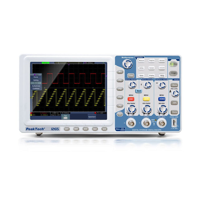
The PeakTech 1265 is an affordable 30 MHz 2-channel digital storage oscilloscope with a high-resolution TFT color display and extensive additional functions. It has a sampling rate of up to 250 MS/s and convinces with its high quality and easy handling with the best price/performance ratio. To quickly display each incoming waveform, simply press the Autoset key and the oscilloscope itself searches for the best possible display. With Autoscale, however, the scaling of the time base can be adjusted in a user-friendly manner. This oscilloscope has a VGA output for displaying the oscilloscope display on an external monitor or projector.
Features
2-channel oscilloscope with 30 MHz analog bandwidth at max. 250 MS/s sampling rate
8 inch (20 cm) TFT color display with 800 x 600 pixels
LAN, USB host, USB device & VGA interface
Autoset function for user-friendly operation
Recording length of max. 10,000 points
Automatic measurement modes, XY mode and FFT function
Specifications
Bandwidth
30 MHz
Channels
2
Screen size (TFT)
8' (20 cm)
Resolution
800 x 600 Pixel
Display Type
Color-TFT
Sampling 1 CH
250 MS/s
Sampling 2 CH
125 MS/s
Hor. scale max.
100 s/div
Hor. scale min.
5 ns/div
Memory depth
10,000 Points
Rise Time
< 14 ns
Vert. resolution
8 Bit
Vert. scale max.
10 V/div
Vert. scale min.
2 mV/div
Interfaces
1x USB, 1x LAN, 1x VGA
Mains voltage
110/240 V AC; 50/60 Hz
Included
PeakTech 1265 Oscilloscope
USB cable
Software CD for Windows
Power cord
2 probes
BNC cable
Carrying case
Manual
Downloads
Software
Datasheet_DE-EN
Datasheet_FR
Datasheet_IT
Datasheet_ES
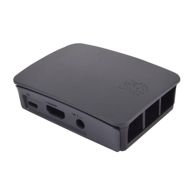
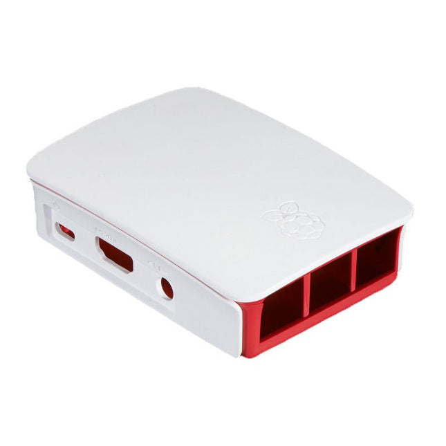
High-quality ABS construction Removable side panels and lid for easy access to GPIO, camera and display connectors Light pipes for power and activity LEDs Extraordinarily handsome Colour: black/grey
High-quality ABS construction Removable side panels and lid for easy access to GPIO, camera and display connectors Light pipes for power and activity LEDs Extraordinarily handsome Colour: white/red
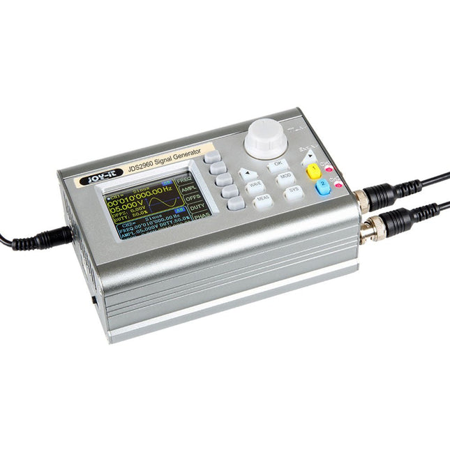
The JOY-iT JDS2960 is a 2-channel signal generator capable of producing signals up to 60 MHz. Its compact design and the option to operate it with a power bank make it ideal for mobile use.
With a variety of waveforms, including sine, square, triangle, pulse, half-wave, and more, it is suitable for various measurement technology applications.
Additionally, the JDS2960 features a 1-channel frequency allocation. Its high frequency accuracy of ±20 ppm and stability of ±1 ppm/3 h ensure excellent signal quality and great flexibility.
The 2.4-inch TFT color display provides user-friendly operation and enables a wide range of applications.
Features
2 Channels
Up to 60 MHz
Robust aluminum housing
1-channel frequency counter
Up to 20 Vpp
Many different pre-programmed waveforms and up to 60 user-defined waveforms
Pulse function
Specifications
Channels
2-channel Signal Generator1-channel Frequency meter
Frequency range
Sine: 0-60 MHzSquare, triangle: 0-25 MHzTTL, Pulse: 0-6 MHz
Signal forms
Sine, square, triangle, pulse, half/solid wave, exponential rise/fall, etc.
Measuring range frequency counter
1-100 MHz
Frequency accuracy
±20 ppm
Frequency stability
±1 ppm/3 h
Sampling rate
266 MSa/s
Display
2,4" TFT color LCD
Vertical shaft resolution
14 bits
Amplitude range
<10 MHz: 0-20 Vpp>10 MHz: 0-10 Vpp
Amplitude resolution
1 mV
Amplitude stability
±5%/5h
Amplitude flatness
<10 MHz: ±5%>10 MHz: ±10%
Impedance of output
50 Ω ±10%
Distortion factor
<0.8% (20 Hz-20 KHz, 0 dBm)
Dimensions
145 x 95 x 55 mm
Weight
900 g
Included
1x JOY-iT JDS2960 2-ch Signal Generator
1x Power supply unit
1x BNC-BNC cable
2x BNC crocodile clip cables
1x USB-DC power cable
1x USB data cable
Downloads
Datasheet
Manual
Software