
Search results for "digitale OR systeme OR mit OR fpgas OR entwickeln OR pdf"
-
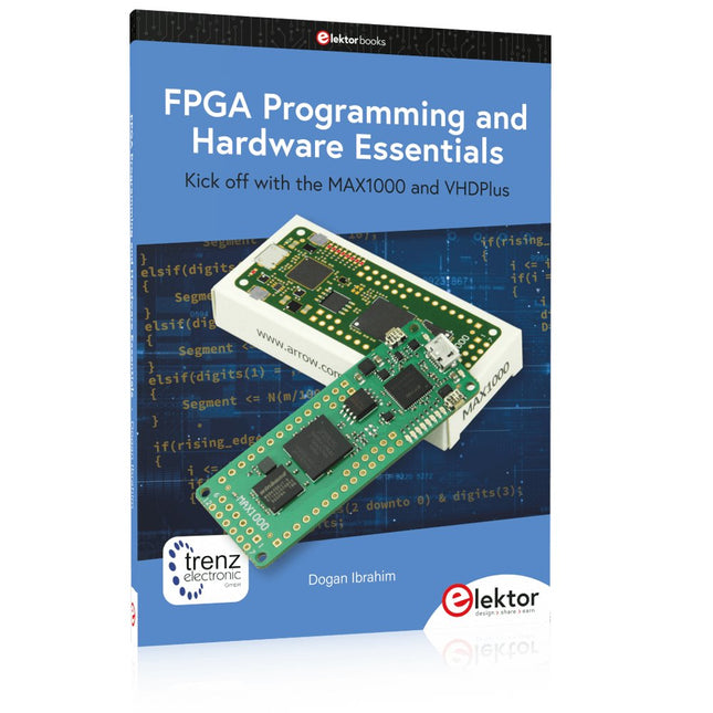
Elektor Publishing FPGA Programming and Hardware Essentials
Kick off with the MAX1000 and VHDPlus Ready to Master FPGA Programming? In this guide, we’re diving into the world of Field Programmable Gate Arrays (FPGAs) – a configurable integrated circuit that can be programmed after manufacturing. Imagine bringing your ideas to life, from simple projects to complete microcontroller systems! Meet the MAX1000: a compact and budget-friendly FPGA development board packed with features like memory, user LEDs, push-buttons, and flexible I/O ports. It’s the ideal starting point for anyone wanting to learn about FPGAs and Hardware Description Languages (HDLs). In this book, you’ll get hands-on with the VHDPlus programming language – a simpler version of VHDL. We’ll work on practical projects using the MAX1000, helping you gain the skills and confidence to unleash your creativity. Get ready for an exciting journey! You’ll explore a variety of projects that highlight the true power of FPGAs. Let’s turn your ideas into reality and embark on your FPGA adventure – your journey starts now! Exciting Projects You’ll Find in This Book Arduino-Driven BCD to 7-Segment Display Decoder Use an Arduino Uno R4 to supply BCD data to the decoder, counting from 0 to 9 with a one-second delay Multiplexed 4-Digit Event Counter Create an event counter that displays the total count on a 4-digit display, incrementing with each button press PWM Waveform with Fixed Duty Cycle Generate a PWM waveform at 1 kHz with a fixed duty cycle of 50% Ultrasonic Distance Measurement Measure distances using an ultrasonic sensor, displaying the results on a 4-digit 7-segment LED Electronic Lock Build a simple electronic lock using combinational logic gates with push buttons and an LED output Temperature Sensor Monitor ambient temperature with a TMP36 sensor and display the readings on a 7-segment LED Downloads Software
€ 39,95
Members: € 35,96
-
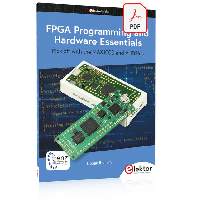
Elektor Digital FPGA Programming and Hardware Essentials (E-book)
Kick off with the MAX1000 and VHDPlus Ready to Master FPGA Programming? In this guide, we’re diving into the world of Field Programmable Gate Arrays (FPGAs) – a configurable integrated circuit that can be programmed after manufacturing. Imagine bringing your ideas to life, from simple projects to complete microcontroller systems! Meet the MAX1000: a compact and budget-friendly FPGA development board packed with features like memory, user LEDs, push-buttons, and flexible I/O ports. It’s the ideal starting point for anyone wanting to learn about FPGAs and Hardware Description Languages (HDLs). In this book, you’ll get hands-on with the VHDPlus programming language – a simpler version of VHDL. We’ll work on practical projects using the MAX1000, helping you gain the skills and confidence to unleash your creativity. Get ready for an exciting journey! You’ll explore a variety of projects that highlight the true power of FPGAs. Let’s turn your ideas into reality and embark on your FPGA adventure – your journey starts now! Exciting Projects You’ll Find in This Book Arduino-Driven BCD to 7-Segment Display Decoder Use an Arduino Uno R4 to supply BCD data to the decoder, counting from 0 to 9 with a one-second delay Multiplexed 4-Digit Event Counter Create an event counter that displays the total count on a 4-digit display, incrementing with each button press PWM Waveform with Fixed Duty Cycle Generate a PWM waveform at 1 kHz with a fixed duty cycle of 50% Ultrasonic Distance Measurement Measure distances using an ultrasonic sensor, displaying the results on a 4-digit 7-segment LED Electronic Lock Build a simple electronic lock using combinational logic gates with push buttons and an LED output Temperature Sensor Monitor ambient temperature with a TMP36 sensor and display the readings on a 7-segment LED Downloads Software
€ 32,95
Members: € 29,66
-
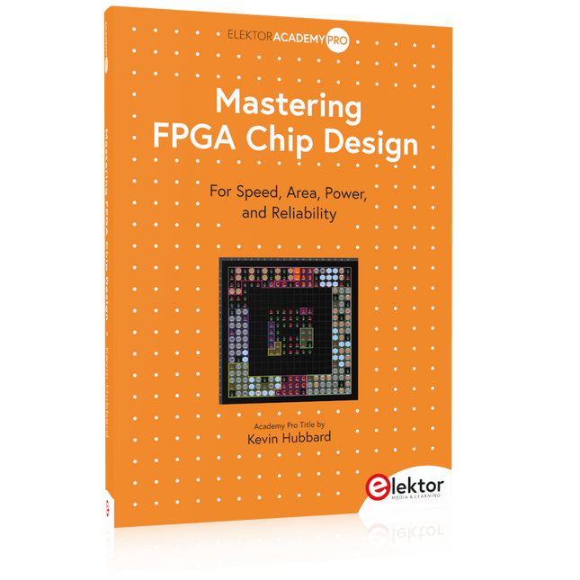
Elektor Publishing Mastering FPGA Chip Design
For Speed, Area, Power, and Reliability This book teaches the fundamentals of FPGA operation, covering basic CMOS transistor theory to designing digital FPGA chips using LUTs, flip-flops, and embedded memories. Ideal for electrical engineers aiming to design large digital chips using FPGA technology. Discover: The inner workings of FPGA architecture and functionality. Hardware Description Languages (HDL) like Verilog and VHDL. The EDA tool flow for converting HDL source into a functional FPGA chip design. Insider tips for reliable, low power, and high performance FPGA designs. Example designs include: Computer-to-FPGA UART serial communication. An open-source Sump3 logic analyzer implementation. A fully functional graphics controller. What you need: Digilent BASYS3 or similar FPGA eval board with an AMD/Xilinx FPGA. Vivado EDA tool suite (available for download from AMD website free of charge). Project source files available from author’s GitHub site.
€ 39,95
Members: € 35,96
-
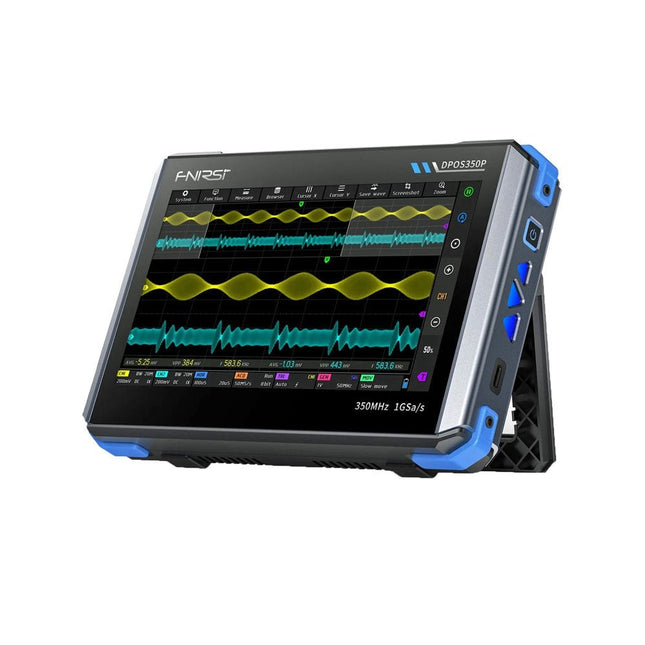
FNIRSI FNIRSI DPOS350P (4-in-1) 2-ch Tablet Oscilloscope (350 MHz) + Signal Generator + Frequency Response Analyzer + Spectrum Analyzer
2 Channels • 350 MHz • 1 GSa/s • 50,000 wfm/s • 7 inch Touchscreen The FNIRSI DPOS350P is a sleek 4-in-1 powerhouse in tablet form! This compact and portable device packs serious functionality: it combines a 2-channel oscilloscope (350 MHz), a signal generator (50 MHz), a frequency response analyzer (50 MHz), and a spectrum analyzer (200 kHz–350 MHz) – all in one unit. Whether you're in R&D, troubleshooting, or field testing, the DPOS350P delivers the tools you need to measure, generate, analyze, and visualize electronic signals with precision and clarity. Its responsive high-resolution touchscreen and intuitive controls make signal analysis fast, flexible and efficient. Features Powerful Multi-Function Integration 350 MHz 2-channel oscilloscope with 1 GSa/s real-time sampling 50 MHz signal generator with 14 standard + custom waveforms Spectrum analyzer (200 kHz–350 MHz): Perfect for EMI, RF & HF testing Frequency response analyzer (FRA) up to 50 MHz High-Performance Waveform Capture 50,000 wfm/s refresh rate for real-time signal clarity 350 MHz bandwidth (single-channel mode) Detects rare and low-probability anomalies Crisp Display & Smooth Operation 7" IPS touchscreen (1024 x 600 resolution) Switch between grayscale and color temperature display Easy to operate in various test environments Reliable, Protected & Fast-Charging High-voltage protection up to 400 V Fast charging with QC 18 W (full charge in 2 hours) Built for stable long-term operation Data Storage & Export Save up to 500 waveform records + 90 screenshots USB export for easy reporting and offline analysis Specifications General Display 7 inch (IPS full viewing angle) Resolution 1024 x 600 pixels Interaction mode Capacitive touch screen Total power consumption 10 W Power-on configuration 5 presets Charging QC 18 W, 12 V/1.5 A (USB-C) Battery 3.7 V, 8000 mAh lithium battery Battery life approx. 3 hours in operation, 5 hours standby Heat dissipation Air cooling Expansion interface USB data port Automatic shutdown 15~60 minutes / off Firmware upgrade Support .iso image upgrade Languages English / Portuguese / Russian / Chinese Dimensions 190 x 128 x 37 mm Oscilloscope Analog channels 2 Analog bandwidth 350 MHz Rise time 1ns Real-time sampling rate 1 GSa/s Memory depth 60 Kpts Input impedance 1 MΩ / 14PF Time base range 5ns ~ 50s Roll time base 50ms ~ 50s Vertical sensitivity 2 mV ~ 20 V (1X) Vertical range 16 mV ~ 160 V (1X) DC accuracy ±2% Time accuracy ±0.01% Input coupling DC / AC Probe attenuation 1X / 10X / 100X Hardware bandwidth limit 150M / 20M High resolution mode 8bit ~ 16bit Parameter measurements 12 types Cursor measurement Time, period, frequency, level, voltage Trigger detection Digital trigger Trigger channel CH1 / CH2 Trigger mode Auto / Single / Normal Trigger edge Rising edge / Falling edge Trigger suppression L1 ~ L3 Trigger level Manual / automatic 10% ~ 90% Screenshot storage 90 pictures Waveform storage 500 groups Background grid Display / hide Waveform movement Coarse adjustment / fine adjustment Overvoltage protection Withstand voltage 400 V Waveform brightness Adjustable Simple FFT display Yes Digital fluorescence Yes Color temperature display Yes X-Y mode Yes ZOOM time base Yes One-key automatic adjustment Yes One-key return to zero Yes Data browser Yes Signal Generator Waveform types 14 standard functions + captured waveform Frequency 0~50 MHz (sine wave only, other waveforms up to 10M/5M/3M) Amplitude 0~5 VPP Offset -2.5 V ~ +2.5V Duty cycle 0.1~99.9% Frequency resolution 1 Hz Amplitude resolution 1 mV Offset resolution 1 mV Duty cycle resolution 0.1% Customizable captured waveform 500 groups Frequency Response Analyzer (FRA) Excitation signal frequency 100 Hz ~ 50 MHz Excitation signal amplitude 0~5 VPP Excitation signal offset -2.5V ~ +2.5V Excitation frequency count 20~500 Cursor measurement Frequency / gain / phase Operating mode Single / cyclic System calibration Yes Spectrum Analyzer Conversion method FFT FFT length 4K ~ 32K Frequency range 200 KHz ~ 350 MHz Level range -60 dBmV ~ +260 dBmV Cursor measurement Frequency / amplitude Marking parameter Maximum energy harmonic Waterfall chart Yes 3D waterfall chart Yes Automatic adjustment Yes System calibration Yes Included 1x FNIRSI DPOS350P Oscilloscope (4-in-1) 2x 350 MHz Probes 1x QC 18 W Fast Charger (EU) 1x USB-C Cable 1x Alligator Clip 1x Storage Bag 1x Manual Downloads Manual Firmware
€ 309,00€ 259,00Best Price
-
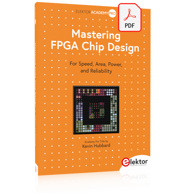
Elektor Digital Mastering FPGA Chip Design (E-book)
For Speed, Area, Power, and Reliability This book teaches the fundamentals of FPGA operation, covering basic CMOS transistor theory to designing digital FPGA chips using LUTs, flip-flops, and embedded memories. Ideal for electrical engineers aiming to design large digital chips using FPGA technology. Discover: The inner workings of FPGA architecture and functionality. Hardware Description Languages (HDL) like Verilog and VHDL. The EDA tool flow for converting HDL source into a functional FPGA chip design. Insider tips for reliable, low power, and high performance FPGA designs. Example designs include: Computer-to-FPGA UART serial communication. An open-source Sump3 logic analyzer implementation. A fully functional graphics controller. What you need: Digilent BASYS3 or similar FPGA eval board with an AMD/Xilinx FPGA. Vivado EDA tool suite (available for download from AMD website free of charge). Project source files available from author’s GitHub site.
€ 32,95
Members: € 29,66
-

Elektor Publishing PID-basierte digitale Regelungstechnik mit Raspberry Pi und Arduino Uno
Der Arduino Uno ist ein Open-Source-Mikrocontroller-Entwicklungssystem, das Hardware, eine integrierte Entwicklungsumgebung (IDE) und eine Vielzahl von Bibliotheken umfasst. Es wird von einer riesigen Gemeinschaft von Programmierern, Elektronikern, Enthusiasten und Akademikern unterstützt. Insbesondere die Bibliotheken erleichtern die Programmierarbeit und reduzieren die Entwicklungszeiten, da sie das Erstellen von Programmen erheblich erleichtern. Der Raspberry Pi 4 kann in vielen Projekten wie Audio- und Videoanwendungen, aber auch in Industriesteuerungen, Robotik, Spielen usw. eingesetzt werden. Dazu bietet er auch WiFi- und Bluetooth-Fähigkeiten, wodurch er sich zudem hervorragend für internetbasierte Steuerungs- und Überwachungsanwendungen eignet. In diesem Buch werden sowohl der Raspberry Pi 4 als auch der Arduino Uno in PID-basierten automatischen Steuerungsanwendungen eingesetzt. Nach einer grundlegenden Theorie der Regelsysteme werden funktionierende und getestete Projekte zur Steuerung realer Systeme mit PID-Reglern vorgestellt. Die Open-Loop-Eigenschaften, die Abstimmung der PID-Parameter und das Closed-Loop-Zeitverhalten der Systeme werden zusammen mit Blockdiagrammen, Schaltplänen und PID-Regelalgorithmen ausführlich diskutiert. Vollständige Programme für den Raspberry Pi und den Arduino Uno runden die im Buch vorgestellten Projekte ab. Die Regelsysteme können problemlos auch auf andere Projekte angewendet werden und die für den Raspberry Pi 4 angegebenen Programme sollten auch mit anderen Modellen der Raspberry Pi-Familie reibungslos funktionieren. Das Buch behandelt folgende Themen: Steuer- und Regelsysteme Analoge und digitale Sensoren Übertragungsfunktionen und zeitkontinuierliche Systeme Systemantwortfunktionen erster und zweiter Ordnung Zeitdiskrete digitale Systeme Zeitkontinuierliche PID-Regler Zeitdiskrete PID-Regler Zweipunkt-Temperaturregelung mit Raspberry Pi und Arduino Uno PID-basierte Temperaturregelung mit Raspberry Pi und Arduino Uno Motorsteuerung mit Raspberry Pi und Arduino Uno Wasserstandsregelung mit Raspberry Pi und Arduino Uno PID-basierte LED-Helligkeitsregelung mit Raspberry Pi und Arduino Uno
€ 39,80
Best Price
-

Elektor Digital Build Your Own Software-Defined Radio (E-book)
Practical Guide to Modular RF Design Build Your Own Software-Defined Radio combines RF circuitry with hardware programming and PC-based signal processing. The e-book presents a modular approach to building a complete SDR system using RF Bricks – from the mechanical framework and RF modules to measurement tools, PC software, and FPGA implementations. Practical explanations guide readers through real signal paths, construction steps, and measurement routines, linking hardware and software into a flexible SDR platform. Key topics include: Mechanical setup: RF Brick template, chassis, and 19-inch module carrier Bridges: USB isolator, I²C level shifter, I²C power switch, and practical examples Signal-chain design with RF Bricks: antennas, band filters, NanoVNA work, preamplifiers, PLLs, demodulators, direct-conversion chains, multiband options, and narrowband bricks RF measurement Bricks: single- and dual-tone sources, NPR methods, noise generators, notch filters, broadband amplifiers, and impedance bridges Useful accessories: ATU-100 tuner, X-Phase QRM eliminator, and firmware notes PC host software: SoapyAudio adjustments, GQRX, SDR++, and added functionality GnuRadio elements: control blocks, SSB demodulation, GUI components, messaging, and filter handling FPGA-based SDR: VHDL, toolchains, ADC/DAC blocks, oversampling, and a complete SSB/CW signal chain With its modular structure and detailed working examples, this e-book offers a practical path to building and extending modern SDR systems. Downloads Software
€ 32,95
Members: € 29,66
-

FNIRSI FNIRSI DLA-16/32 Plus Logic Analyzer (16/32 Channels)
The FNIRSI DLA Series combines high-performance USB 3.0 logic analysis with flexible multi-channel signal capture for debugging and analyzing digital circuits and embedded systems. The series is available in two versions: the DLA-16 Plus with 16 digital channels and the DLA-32 Plus with 32 digital channels. Both models offer sampling rates of up to 1 GSa/s, 4 Gbit of onboard memory, and support for 120+ protocol decoders. With Buffer, Stream, and Roll acquisition modes, they are suitable for both high-speed signal analysis and long-term monitoring. Choose the DLA-16 Plus for higher sampling rates when using all channels, or the DLA-32 Plus when you need more channels and advanced serial and parallel triggering. Features Available with 16 or 32 digital input channels Up to 1 GSa/s sampling rate DLA-16 Plus: up to 500 MSa/s with all 16 channels DLA-32 Plus: up to 250 MSa/s with all 32 channels 4 Gbit onboard memory High-speed USB 3.0 interface Acquisition modes: Buffer, Stream, and Roll Support for 120+ protocol decoders Advanced triggering options 4 PWM outputs with 1 Hz–20 MHz frequency range CSV and BIN data export Specifications DLA-16 Plus DLA-32 Plus Digital Channels 16 32 Max. Sampling Rate 1 GSa/s Sampling Rate (1 Channel) 1 GSa/s Sampling Rate (8 Channels) 1 GSa/s Max. Buffer Sampling 16 CH @ 500 MSa/s 32 CH @ 250 MSa/s Max. Stream Sampling 16 CH @ 125 MSa/s 32 CH @ 50 MSa/s Hardware Memory 4 Gbit Interface USB 3.0 / USB-C Max. USB Transfer Rate 5 Gbit/s Acquisition Modes Buffer / Stream / Roll Protocol Decoders 120+ Custom Protocol Support Yes Trigger Modes Rising Edge, Falling Edge, High, Low, Any Edge Advanced Trigger Standard Triggering Serial and Parallel Parallel Trigger Stages – Up to 16 PWM Outputs 4 PWM Output Voltage 3.3 V PWM Frequency 1 Hz–20 MHz Data Export CSV, BIN Dimensions 90 x 81 x 11.5 mm Included 1x FNIRSI DLA-16/32 Plus Logic Analyzer 4 Sets x 5 Shielded Cables 18x Mini IC Test Hooks (High Configuration Version) 1x USB 3.0 Data Cable 10x IC Test Hooks 1x Transparent Storage Case for Test Hooks 1x Storage Bag 1x Manual Downloads Manual
-

Elektor Publishing Software Defined Radio zum Selbstbau
Praktischer Einstieg mit Arduino, GnuRadio und FPGA Das Thema „Software Defined Radio“ ist facettenreich: Neben der Schaltungstechnik ist auch eine Einarbeitung in die Programmierung von Hardware und PC wichtig. Ein schrittweises Vorgehen erleichtert Ihnen den Einstieg. Mit dem im Buch vorgestellten modularen „RF Bricks“-Konzept werden Sie zum Architekten Ihrer Signalkette. Auf einem Chassis angeordnet gewährleisten die Module einen soliden und gut abgeschirmten Aufbau, den Sie einfach verändern und mit eigenen Ideen anreichern können. Der skalierbare Aufbau bildet Ihr Blockschaltbild auch mechanisch ab – die so gewonnene Übersicht kann in der Aus- und Weiterbildung nützlich sein. Ein Arduino in Ihrem Chassis kommuniziert nach einigen Anpassungen mit üblichen SDR-Programmen, z. B. SDRCPP, GQRX und CubicSDR auf einer Linux-Plattform. Damit können Sie Ihren Empfänger direkt per Mausklick abstimmen. Wenn Sie Blockschaltbilder mögen, ist GnuRadio ein natürlicher Partner der „RF Bricks“. Mit einem selbst programmierten Python-Block gelingt Ihnen in GnuRadio die Fernsteuerung Ihres Empfängers. Im GnuRadio-Universum können Sie Ihre GUI stufenweise ausbauen, behalten dabei aber immer volle Kontrolle über die inneren Abläufe des Programms. Mit einem FPGA können zeitaufwändige Operationen auch direkt in die Hardware verlagert werden. Sie bauen stufenweise einen Doppelsuperhet auf und entwickeln die Filterkoeffizienten für FIR-Filter mit Scilab. Das in VHDL realisierte Weaver-Schema rundet diesen Empfänger ab, der mit hoher Empfindlichkeit und Dynamik aufwarten kann. Mit dem gewonnen Überblick und Ihrer neuen Hardware können Sie die einzelnen Aspekte des Themenkomplexes SDR beliebig weiter vertiefen. Downloads Software
€ 44,80
Best Price
-
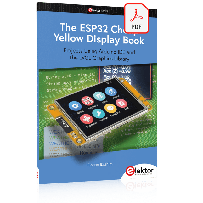
Elektor Digital The ESP32 Cheap Yellow Display Book (PDF)
Projects Using Arduino IDE and the LVGL Graphics Library The ESP32 is probably one of the most popular microcontrollers used by many people, including students, hobbyists, and professional engineers. Its low cost, coupled with rich features makes it a popular device to use in many projects. Recently, a board called the ESP32 Cheap Yellow Display (CYD for short) is available from its manufacturers. The board includes a standard ESP32 microcontroller together with a 320x240 pixel TFT display. Additionally, the board provides several connectors for interfaces such as GPIO, serial port (TX/RX), power and Ground. The inclusion of a TFT display is a real advantage as it enables users to design complex graphics-based projects without resorting to an external LCD or graphics displays. The book describes the basic hardware of the ESP32 CYD board and provides details of its on-board connectors. Many basic, simple, and intermediate-level projects are given in the book based on the ESP32 CYD, using the highly popular Arduino IDE 2.0 integrated development environment. The use of both the basic graphics functions and the use of the popular LVGL graphics library are discussed in the book and projects are given that use both types of approaches. All the projects given in the book have been tested and are working. The block diagram, circuit diagram, and the complete program listings and program descriptions of all the projects are given with explanations. Readers can use the LVGL graphics library to design highly popular eye-catching full-color graphics projects using widgets such as buttons, labels, calendars, keypads, keyboards, message boxes, spinboxes, sliders, charts, tables, menus, bars, switches, drop-down lists, animations, and many more widgets.
€ 29,95
Members: € 26,96


-
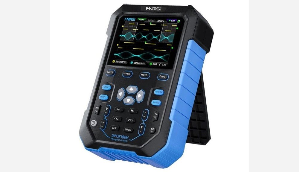
, by Clemens Valens FNIRSI DPOX180H 2-in-1 Digital Phosphor Oscilloscope (Review)
Oscilloscopes sure have made a lot of progress over the past two decades. Twenty years ago, I still used my single-beam analog 20 MHz CRT oscilloscope...
-
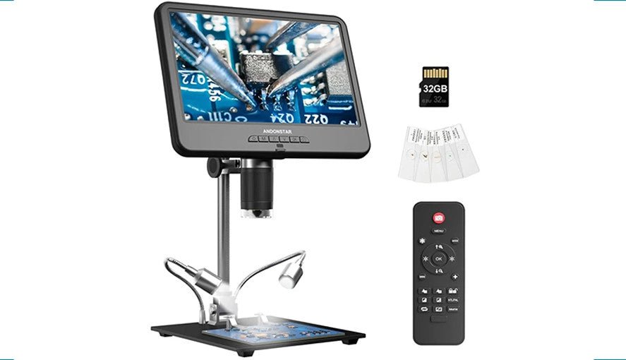
, by Clemens Valens Explore the Tiny World: Andonstar AD210 Digital Microscope in Focus
The Andonstar AD210 offers an accessible entry point into the world of digital microscopy with its expansive 10.1" display. Designed primarily for electronics labs, this...
