This book details the use of the Arduino Uno and the Raspberry Pi 4 in practical CAN bus based projects. Using either the Arduino Uno or the Raspberry Pi with off-the-shelf CAN bus interface modules considerably ease developing, debugging, and testing CAN bus based projects.
This book is written for students, practicing engineers, enthusiasts, and for everyone else wanting to learn more about the CAN bus and its applications. The book assumes that the reader has some knowledge of basic electronics. Knowledge of the C and Python programming languages and programming the Arduino Uno using its IDE and Raspberry Pi will be useful, especially if the reader intends to develop microcontroller-based projects using the CAN bus.
The book should be a useful source of reference material for anyone interested in finding answers to questions such as:
What bus systems are available for the automotive industry?
What are the principles of the CAN bus?
How can I create a physical CAN bus?
What types of frames (or data packets) are available in a CAN bus system?
How can errors be detected in a CAN bus system and how dependable is a CAN bus system?
What types of CAN bus controllers exist?
How do I use the MCP2515 CAN bus controller?
How do I create 2-node Arduino Uno-based CAN bus projects?
How do I create 3-node Arduino Uno-based CAN bus projects?
How do I set the acceptance masks and acceptance filters?
How do I analyze data on the CAN bus?
How do I create 2-node Raspberry Pi-based CAN bus projects?
How do I create 3-node Raspberry Pi-based CAN bus projects?
Projects with Arduino Uno & Raspberry Pi with Examples for the MCP2515 CAN Bus Interface Module
This book details the use of the Arduino Uno and the Raspberry Pi 4 in practical CAN bus based projects. Using either the Arduino Uno or the Raspberry Pi with off-the-shelf CAN bus interface modules considerably ease developing, debugging, and testing CAN bus based projects.
This book is written for students, practicing engineers, enthusiasts, and for everyone else wanting to learn more about the CAN bus and its applications. The book assumes that the reader has some knowledge of basic electronics. Knowledge of the C and Python programming languages and programming the Arduino Uno using its IDE and Raspberry Pi will be useful, especially if the reader intends to develop microcontroller-based projects using the CAN bus.
The book should be a useful source of reference material for anyone interested in finding answers to questions such as:
What bus systems are available for the automotive industry?
What are the principles of the CAN bus?
How can I create a physical CAN bus?
What types of frames (or data packets) are available in a CAN bus system?
How can errors be detected in a CAN bus system and how dependable is a CAN bus system?
What types of CAN bus controllers exist?
How do I use the MCP2515 CAN bus controller?
How do I create 2-node Arduino Uno-based CAN bus projects?
How do I create 3-node Arduino Uno-based CAN bus projects?
How do I set the acceptance masks and acceptance filters?
How do I analyze data on the CAN bus?
How do I create 2-node Raspberry Pi-based CAN bus projects?
How do I create 3-node Raspberry Pi-based CAN bus projects?
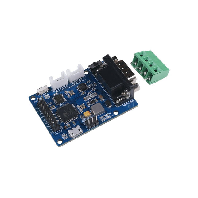
The Seeed Studio CANBed – Arduino CAN-BUS Development Kit integrates an ATmega32U4 microcontroller, eliminating the need for an external Arduino board. It combines an MCP2515 CAN Bus controller and an MCP2551 CAN Bus transceiver on a single board, providing a compact and reliable CAN communication solution.
Features
ATmega32U4 with Arduino Leonardo bootloader on the board
MCP2515 CAN Bus controller and MCP2551 CAN Bus transceiver
OBD-II and CAN standard pinout selectable at the sub-D connector
Compatible with Arduino IDE
Parameter
Value
MCU
ATmega32U4(with Arduino Leonardo bootloader)
Clock Speed
16 MHz
Flash Memory
32 KB
SRAM
2.5 KB
EEPROM
1 KB
Operate Voltage (CAN-BUS)
9 V - 28 V
Operate Voltage (MicroUSB)
5 V
Input Interface
sub-D
Included
CANBed PCBA
sub-D connector
4PIN Terminal
2x 4PIN 2.0 Connector
1x 9x2 2.54 Header
1x 3x2 2.54 Header
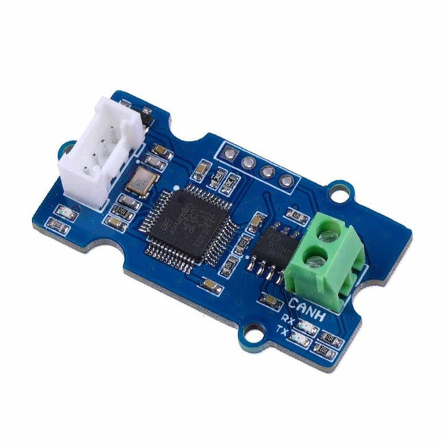
This Grove CAN-BUS Module based on GD32E103 adopts a brand-new design, uses the cost-effective and high-performance GD32E103 microcontroller as the main control and cooperates with a firmware we wrote to complete the function of the serial port to CAN FD. Features
Support CAN communication: Implements CAN FD at up to 5 Mb/s
Easy to program: Support AT command which enables simple serial port programming
Grove ecosystem: 20 x 40 x 10 mm small size, 4-pin Grove connector to plug and play, Arduino compatible This Grove CAN-BUS Module supports CAN FD(CAN with Flexible Data-Rate) communication, which is an extension to the original CAN protocol as specified in ISO 11898-1 that responds to increased bandwidth requirements in automotive networks. In CAN FD, the data rate (i.e. number of bits transmitted per second) is increased to be 5 times faster than the classic CAN (5 Mbit/s for the data payload only, the arbitration bit rate is still limited to 1Mbit/s for compatibility). It supports AT command which enables simple serial port programming. This Grove CAN-BUS Module is based on GD32E103 with a frequency up to 120 MHz. It has a flash size from 64 KB to 128 KB and an SRAM size from 20 KB to 32 KB. Applications Car hacking: allows different parts of the vehicle to talk to each other, including the engine, the transmission, and the brakes. Windows, doors, and mirror adjustment. 3D Printers Building automation Lighting control systems Medical instruments and equipment Specifications MCU GD32E103 UART baud rate Up to 115200 (default 9600) CAN FD baud rate Up to 5 Mb/s Indicator TX and RX led Working voltage 3.3 V Grove connector 4-pin Grove connector to plug and play Size 20 x 40 x 10 mm Downloads Datasheet GitHub
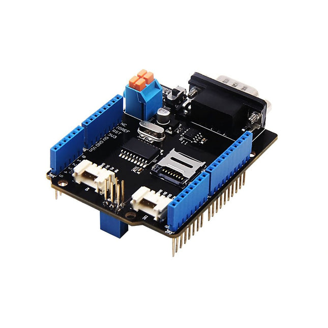
Features Implements CAN V2.0B at up to 1 Mb/s Industrial standard 9 pin sub-D connector OBD-II and CAN standard pinout selectable. Changeable chip select pin Changeable CS pin for TF card slot Changeable INT pin Screw terminal that easily to connect CAN_H and CAN_L Arduino Uno pin headers Micro SD card holder 2 Grove connectors (I2C and UART) SPI Interface up to 10 MHz Standard (11 bit) and extended (29 bit) data and remote frames Two receive buffers with prioritized message storage
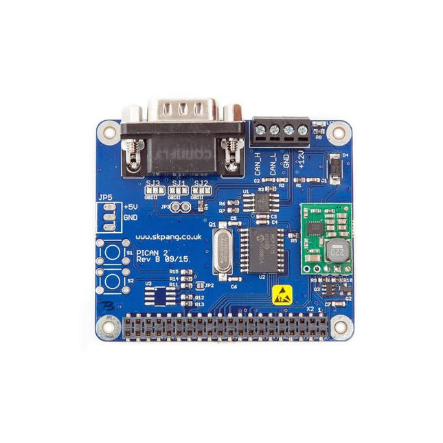
This PiCAN 2 board provides CAN-Bus capability for the Raspberry Pi 2/3. It uses the Microchip MCP2515 CAN controller with MCP2551 CAN transceiver. Connection are made via DB9 or 3-way screw terminal. This board includes a switch mode power suppler that powers the Raspberry Pi is well.
Easy to install SocketCAN driver. Programming can be done in C or Python.
Not suitable for Raspberry Pi 4, please use PiCAN 3 instead.
Features
CAN v2.0B at 1 Mb/s
High speed SPI Interface (10 MHz)
Standard and extended data and remote frames
CAN connection via standard 9-way sub-D connector or screw terminal
Compatible with OBDII cable
Solder bridge to set different configuration for DB9 connector
120Ω terminator ready
Serial LCD ready
LED indicator
Foot print for two mini push buttons
Four fixing holes, comply with Pi Hat standard
SocketCAN driver, appears as can0 to application
Interrupt RX on GPIO25
5 V/1 A SMPS to power Raspberry Pi and accessories from DB9 or screw terminal
Reverse polarity protection
High efficiency switch mode design
6-20 V input range
Optional fixing screws – select at bottom of this webpage
Downloads
User guide
Schematic Rev B
Writing your own program in Python
Python3 examples in Github
Elektor GREEN en GOLD leden kunnen deze uitgave hier downloaden.
Nog geen lid? Klik hier om een lidmaatschap af te sluiten.
Project-update: ESP32-gebaseerde energiemeterwe gaan verder met het prototype
Optimalisatie van balkon PV-centralesoverwegingen, interessante feiten en berekeningen
ESP32 met OpenDTU voor balkoncentralesgegevens van kleine omvormers via MCU’s uitlezen
Regelbare lineaire labvoeding0...50 V / 0...2 A + dubbele symmetrische voeding
Energieopslag – vandaag en morgeneen vraaggesprek met Simon Engelke
2024: een AI-odysseehet houdt nog lang niet op
Bluetooth LE op de STM32meetwaarden op afstand uitlezen
Mensvriendelijk slim keuken-voorraadsysteem
MAUI: programmeren voor PC, tablet en smartphonehet nieuwe framework in theorie en praktijk
ChatMagLevkunstmatig intelligente levitatie
Eenvoudige PV-regelaarbouw je eerste, volledig functionele PV-energiebeheersysteem
Koude-kathode-buizenvreemde onderdelen
Uit het leven gegrepennostalgie
Alle begin......bekijkt de FET
CAN-bus voor de Arduino UNO R4: een tutorialtwee UNO R4’s nemen de bus!
Elektor infographicvoeding en energie
Vergelijking van vermogensdichtheid en vermogensefficiëntie
Aluminium elektrolytische condensatorenstoringspotentieel in audiotechnologie
USB testen en metenmet de Fnirsi FNB58
De Pixel Pump pick&place-tooleenvoudiger handmatige assemblage van SMT-printen
Oost West Lab Bestnog niet zo lang geleden, in een land heel ver van hier...
“In de wereld van ethiek in elektronica kunnen zelfs kleine stappen een aanzienlijke invloed hebben.”
Ethiek in elektronicade OECD Guidelines en het Lieferkettensorgfaltspflichtengesetz
Chadèche: slimme NiMH-(ont)laderlezersproject in het kort
Project 2.0correcties, updates en brieven van lezers
IMAGE PROCESSING WITH THE NVIDIA JETSON NANO (PART 2)Image Recognition Using Edge Impulse
ELEKTOR JUMPSTARTER NEWSUpcoming Campaigns
AN OPEN-SOURCE GPS TRACKING PLATFORMTraccar Maps Vehicle Tracking Without the Need for a Third-Party Cloud Server
JOY-IT LCR-T7 MULTI-FUNCTION TESTERTesting Passives, Discrete Semiconductors and IR Remote Controls
NOISE SYNTHESIZERFrom Noise to Music with the PRBSynth1
STARTING OUT IN ELECTRONICSEasier than Imagined! ... Continuing with the Coil
UNDERSTANDING THE NEURONS IN NEURAL NETWORKS (PART 2)Logical Neurons
ISSUES WITH SECURITY? FIGHT FIRE WITH FIRE!Flashbulb-Protected Analogue Memory Add-on For the Tamper-Evident Box LCR METER POSTER
BLUETOOTH BEACONS IN PRACTICEBeacons Light the Way Ahead
C PROGRAMMING ON RASPBERRY PICommunicating over Wi-Fi (Sample Chapter)
EMC PRE-COMPLIANCE TEST FOR YOUR DC-POWERED PROJECT (PART 2)The Hardware and How to Use It
HANDS ON THE PARALLAX PROPELLER 2 (PART 5)Inside the Smart Pin
MODBUS OVER WLAN (PART 1)Hardware and Programming
HOMELAB TOURSWhere the Junior Computer Is Brought to Life Again
BUILD YOUR OWN HIGH-PRECISION CALIBRATOR-10 V to +10 V, 0 to 40 mA, 0.001%
ARDUINO NANO RP2040 CONNECTRaspberry Pi RP2040 + Wi-Fi + Bluetooth THE PHYSICAL BODY OF ARTIFICIAL INTELLIGENCE
ERR-LECTRONICSCorrections, Updates and Readers’ Letters
CREATE GUIS WITH PYTHONIntroducing guizero
CO2 METER KIT FOR THE CLASSROOMAn ESP8266-Based Device from the University of Applied Sciences Aachen
NOSTALGIC MK484 MW/LW RADIO...Always Fun to Build!
ELEKTOR @ 60Let There Be Light!
HEXADOKUThe Original Elektorized Sudoku