Maker Line is a line sensor with 5 x IR sensors array that is able to track line from 13 mm to 30 mm width.
The sensor calibration is also simplified. There is no need to adjust the potentiometer for each IR sensor. You just have to press the calibrate button for 2 seconds to enter calibration mode. Afterwards you need to sweep the sensors array across the line, press the button again and you are good to go.
The calibration data is saved in EEPROM and it will stay intact even if the sensor has been powered off. Thus, calibration only needs to be carried out once unless the sensor height, line color or background color has changed.
Maker Line also supports dual outputs: 5 x digital outputs for the state of each sensor independently, which is similar to conventional IR sensor, but you get the benefit of easy calibration, and also one analog output, where its voltage represents the line position. Analog output also offers higher resolution compared to individual digital outputs. This is especially useful when high accuracy is required while building a line following robot with PID control.
Features
Operating Voltage: DC 3.3 V and 5 V compatible (with reverse polarity protection)
Recommended Line Width: 13 mm to 30 mm
Selectable line color (light or dark)
Sensing Distance (Height): 4 mm to 40 mm (Vcc = 5 V, Black line on white surface)
Sensor Refresh Rate: 200 Hz
Easy calibration process
Dual Output Types: 5 x digital outputs represent each IR sensor state, 1 x analog output represents line position.
Support wide range of controllers such as Arduino, Raspberry Pi etc.
Downloads
Datasheet
Tutorial: Building A Low-Cost Line Following Robot
The Maker pHAT is the solution to the most common problems beginners face starting with Raspberry PI. Its intelligent and simple design makes it easy to attach to your Pi, and it helps you avoid all the tedious work of connection various other accessories. Additionally, the LEDs corresponding to each pin makes it extremely easy to see where a potential problem lies
The Maker pHat has the same size as the Raspberry Pi Zero with all 4mounting holes aligned. However, it can be used with Raspberry Pi 3B, 3B+ and 3A+, by inserting a 2 x 20 stacking header.
Features
Raspberry Pi Zero size, stack perfectly on to Raspberry Pi Zero
Compatible with standard size Raspberry Pi 3B / 3B+, medium size Raspberry Pi 3A+ and smaller size Raspberry Pi Zero / W / WH.
Standard Raspberry Pi GPIO footprint.
LED array for selected GPIO pins (GPIO 17, 18, 27, 22, 25, 12, 13, 19).
3x on board programmable push buttons (GPIO 21, 19 and 20, need to configure as input pull up).
Onboard active buzzer (GPIO 26).
Proper labels for all GPIOs, including SPI, UART, I2C, 5V, 3.3V, and GND.
Utilize USB Micro-B socket for 5V input and USB to UART communication.
USB serial facilitated by the FT231X
Input voltage: USB 5 V, from a computer, power bank or a standard USB adapter.
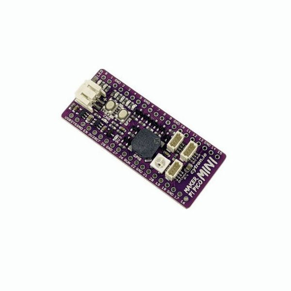
Love the Cytron Maker Pi Pico (SKU 19706) but can't fit it into your project? Now there is the Cytron Maker Pi Pico Mini W. Powered by the awesome Raspberry Pi Pico W, it also inherited most of the useful features from its bigger sibling such as GPIO status LEDs, WS2812B Neopixel RGB LED, passive piezo buzzer, and not forget the user button and reset button. Features Powered by Raspberry Pi Pico W Single-cell LiPo connector with overcharge / over-discharge protection circuit, rechargeable via USB. 6x Status indicator LEDs for GPIOs 1x Passive piezo buzzer (Able to play musical tone or melody) 1x Reset button 1x User programmable button 1x RGB LEDs (WS2812B Neopixel) 3x Maker Ports, compatible with Qwiic, STEMMA QT, and Grove (via conversion cable) Support Arduino IDE, CircuitPython and MicroPython Dimension: 23.12 x 53.85 mm Included 1x Maker Pi Pico Mini W (pre-soldered Raspberry Pi Pico W with preloaded CircuitPython) 3x Grove to JST-SH (Qwiic / STEMMA QT) Cable Downloads Maker Pi Pico Mini Datasheet Maker Pi Pico Mini Schematic Maker Pi Pico Mini Pinout Diagram Official Raspberry Pi Pico Page Getting started with Raspberry Pi Pico CircuitPython for Raspberry Pi Pico Raspberry Pi Pico Datasheet RP2040 Datasheet Raspberry Pi Pico Python SDK Raspberry Pi Pico C/C++ SDK
This book is for people who want to understand how AC drives (also known as inverter drives) work and how they are used in industry by showing mainly the practical design and application of drives.
The key principles of power electronics are described and presented in a simple way, as are the basics of both DC and AC motors. The different parts of an AC drive are explained, together with the theoretical background and the practical design issues such as cooling and protection.
An important part of the book gives details of the features and functions often found in AC drives and gives practical advice on how and where to use these. Also described is future drive technology, including a matrix inverter.
The mathematics is kept to an essential minimum. Some basic understanding of mechanical and electrical theory is presumed, and a basic knowledge of single andthree phase AC systems would be useful.
Anyone who uses or installs drives, or is just interested in how these powerful electronic products operate and control modern industry, will find this book fascinating and informative.
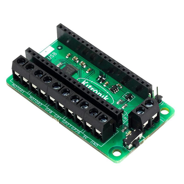
This board allows the Raspberry Pi Pico (connected via pin header) to drive two motors simultaneously with full forward, reverse & stop control, making it ideal for Pico controlled buggy projects. Alternatively, the board can be used to power a stepper motor. The board features the DRV8833 motor driver IC, which has built-in short circuit, over current and thermal protection.
The board has 4 external connections to GPIO pins and a 3 V and GND supply from the Pico. This allows for additional IO options for your buggy builds that can be read or controlled by the Pico. In addition there is an on/off switch and power status LED, allowing you to see at a glance if the board is powered up and save your batteries when your project is not in use.
To use the motor driver board, the Pico should have a soldered pin header and be inserted firmly into the connector. The board produces a regulated supply that is fed into the 40-way connector to power the Pico, removing the need to power the Pico directly. The motor driver board is powered via either screw terminals or a servo style connector.
Kitronik has developed a micro-python module and sample code to support the use of the Motor Driver board with the Pico. This code is available in the GitHub repo.
Features
A compact yet feature-packed board designed to sit at the heart of your Raspberry Pi Pico robot buggy projects.
The board can drive 2 motors simultaneously with full forward, reverse, and stop control.
It features the DRV8833 motor driver IC, which has built-in short circuit, over current and thermal protection.
Additionally, the board features an on/off switch and power status LED.
Power the board via a terminal block style connector.
The 3V and GND pins are also broken out, allowing external devices to be powered.
Code it with MicroPython via an editor such as the Thonny editor.
Dimensions: 63 mm (L) x 35 mm (W) x 11.6 mm (H)
Download
Datasheet
Add colors to your projects with this collection of red, green, yellow, blue and white LEDs. They come with various current limiting resistors in order to protect the parts and control the brightness.Included
10 mm LEDs
1x red
1x green
1x yellow
1x blue
1x white
5 mm LEDs
5x red
5x green
5x yellow
5x blue
5x white
3 mm LEDs
5x red
5x green
5x yellow
5x blue
5x white
25x 330 Ω resistors
10x 1 kΩ resistors
10x 10 kΩ resistors
10x 100 kΩ resistors
10x 1 MΩ resistors
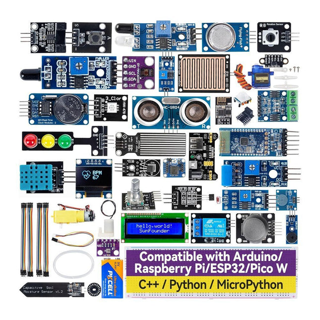
Discover endless creativity with the Universal Maker Sensor Kit, designed for use with Raspberry Pi, Pico W, Arduino, and ESP32. This versatile kit offers compatibility across popular development platforms, including Arduino Uno R4 Minima/WiFi, Uno R3, Mega 2560, Raspberry Pi 5, 4, 3B+, 3B, Zero, Pico W, and ESP32.
Featuring over 35 sensors, actuators, and displays, it's perfect for projects ranging from environmental monitoring and smart home automation to robotics and interactive gaming. Step-by-step tutorials in C/C++, Python, and MicroPython guide beginners and experienced makers alike through 169 exciting projects.
Features
Wide Compatibility: Fully supports Arduino (Uno R3, Uno R4 Minima/WiFi, Mega 2560), Raspberry Pi (5, 4, 3B+, 3B, Zero, Pico W), and ESP32, enabling extensive flexibility across numerous development platforms. Includes instructions for building 169 projects.
Comprehensive Components: Features more than 35 sensors, actuators, and display modules suitable for diverse projects such as environmental monitoring, smart home automation, robotics, and interactive game controllers.
Detailed Tutorials: Provides clear, step-by-step tutorials covering Arduino, Raspberry Pi, Pico W, ESP32, and each included component. Tutorials are available in C/C++, Python, and MicroPython, catering effectively to both beginners and experienced makers.
Suitable for All Skill Levels: Offers structured projects designed to guide users seamlessly from beginner to advanced proficiency in electronics and programming, enhancing creativity and technical expertise.
Included
Breadboard
Button Module
Capacitive Soil Moisture Module
Flame Sensor Module
Gas/Smoke Sensor Module (MQ2)
Gyroscope & Accelerometer Module (MPU6050)
Hall Sensor Module
Infrared Speed Sensor Module
IR Obstacle Avoidance Sensor Module
Joystick Module
PCF8591 ADC DAC Converter Module
Photoresistor Module
PIR Motion Module (HC-SR501)
Potentiometer Module
Pulse Oximeter and Heart Rate Sensor Module (MAX30102)
Raindrop Detection Module
Real Time Clock Module (DS1302)
Rotary Encoder Module
Temperature Sensor Module (DS18B20)
Temperature and Humidity Sensor Module (DHT11)
Temperature, Humidity & Pressure Sensor (BMP280)
Time of Flight Micro-LIDAR Distance Sensor (VL53L0X)
Touch Sensor Module
Ultrasonic Sensor Module (HC-SR04)
Vibration Sensor Module (SW-420)
Water Level Sensor Module
I²C LCD 1602
OLED Display Module (SSD1306)
RGB LED Module
Traffic Light Module
5 V Relay Module
Centrifugal Pump
L9110 Motor Driver Module
Passive Buzzer Module
Servo Motor (SG90)
TT Motor
ESP8266 Module
JDY-31 Bluetooth Module
Power Supply Module
Documentation
Online Tutorial
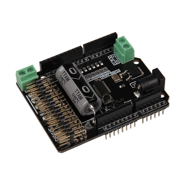
The Motorino board is an extension-board to control and use up to 16 PWM-controlled 5V-Servo-motors.
The included clock generator ensures a very precise PWM signal and a very precise positioning.
The board has 2 inputs for voltage from 4.8 V to 6 V which can be used for up to 11 A. With this input, a perfect power supply is always guaranteed and even bigger projects are no problem.
The supply runs directly over the Motorino which provides a connection for voltage, ground and control.
With the build in capacitor, the voltage is buffered which prevents a sudden voltage-drop at a high load. But there is also the possibility to connect another capacitor.
The control and the programing can be done, as usual, with the Arduino. Manuals and code examples allows a quick introduction for beginners.
Specifications
Special features
16 Channels, own clock generator
Input 1
Coaxial power connector 5.5 / 2.1 mm, 4.8-6 V / 5 A max
Input 2
Screw-terminal, 4.8-6 V / 6 A max
Communication
16 x PWM
Compatible with
Arduino Uno, Mega and may more microcontroller with Arduino compatible pinout
Dimensions
69 x 24 x 56 mm
Included
Board, Manual, Retail package
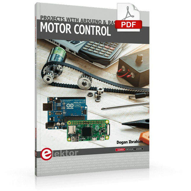
This book is about DC electric motors and their use in Arduino and Raspberry Pi Zero W based projects. The book includes many tested and working projects where each project has the following sub-headings:
Title of the project
Description of the project
Block diagram
Circuit diagram
Project assembly
Complete program listing of the project
Full description of the program
The projects in the book cover the standard DC motors, stepper motors, servo motors, and mobile robots. The book is aimed at students, hobbyists, and anyone else interested in developing microcontroller based projects using the Arduino Uno or the Raspberry Pi Zero W.
One of the nice features of this book is that it gives complete projects for remote control of a mobile robot from a mobile phone, using the Arduino Uno as well as the Raspberry Pi Zero W development boards. These projects are developed using Wi-Fi as well as the Bluetooth connectivity with the mobile phone. Readers should be able to move a robot forward, reverse, turn left, or turn right by sending simple commands from a mobile phone. Full program listings of all the projects as well as the detailed program descriptions are given in the book. Users should be able to use the projects as they are presented, or modify them to suit to their own needs.
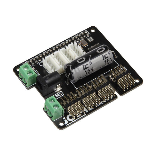
The MotoPi is an extension-board to control and use up to 16 PWM-controlled 5 V servo motors. The board can be additional powered by a voltage between 4.8 V and 6 V so a perfect supply is always guaranteed and even larger projects can be powered.
With the additional power supply and the integrated Analog-Digital-Converter, new possibilities can be reached. An additional power supply per motor is not required anymore because all connections (Voltage, Ground, Control) are directly connected to the board.
The control and the programing can be directly done, as usual, on the Raspberry Pi.
Specifications
Special features
16 Channels, own clock generator, Inkl. Analog Digital Converter
Input 1
Coaxial power connector 5.5 / 2.1 mm, 5 V / 6 A max
Input 2
Screw terminal, 4.8-6 V / 6 A max
Compatible with
Raspberry Pi A+, B+, 2B, 3B
Dimensions
65 x 56 x 24 mm
Scope of supply
Board, manual, fixing material
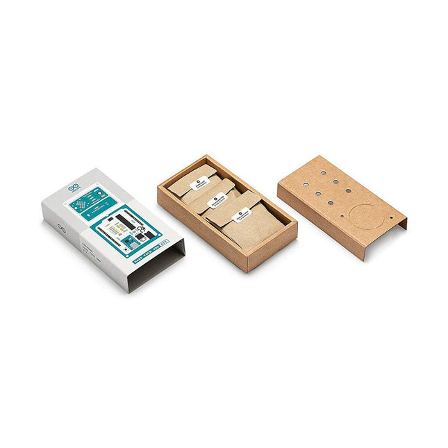
Learn the basics of electronics by assembling manually your Arduino Uno, become familiar with soldering by mounting every single component, and then unleash your creativity with the only kit that becomes a synth!
The Arduino Make-Your-Uno kit is really the best way to learn how to solder. And when you are done, the packaging allows you to build a synth and make your music.
A kit with all the components to build your very own Arduino Uno and audio synthesizer shield.
The Make-Your-Uno kit comes with a complete set of instructions in a dedicated content platform. This includes video material, a 3D interactive viewer for following detailed instructions, and how to program your board once it is finished.
This kit contains:
Arduino Make-Your-Uno
1x Make-Your-Uno PCB
1x USB C Serial adapter Board
7x Resistors 1k Ohm
2x Resistors 10k Ohm
2x Resistors 1M Ohm
1x Diode (1N4007)
1x 16 MHz Crystal
4x Yellow LEDs
1x Green LED
1x Push-Button
1x MOSFET
1x LDO (3.3 V)
1x LDO (5 V)
3x Ceramic capacitors (22pF)
3x Electrolytic capacitors (47uF)
7x Polyester capacitors (100nF)
1x Socket for ATMega 328p
2x I/O Connectors
1x Connector header 6 pins
1x Barrel jack connector
1x ATmega 328p Microcontroller
Arduino Audio Synth
1x Audio Synth PCB
1x Resistor 100k Ohm
1x Resistor 10 Ohm
1x Audio amplifier (LM386)
1x Ceramic capacitors (47nF)
1x Electrolytic capacitors (47uF)
1x Electrolytic capacitors (220uF)
1x Polyester capacitor (100nF)
4x connectors pin header
6x potentiometer 10k Ohm with plastic knobs
Spare parts
2x Electrolytic capacitors (47uF)
2x Polyester capacitor (100nF)
2x Ceramic capacitors (22pF)
1x Push-Button
1x Yellow LEDs
1x Green LED
Mechanical parts
5x Spacers 12 mm
11x Spacers 6 mm
5x screw nuts
2x screws 12 mm
,
by Udo Bormann
Electronics Projects Archive for Engineers, Makers & Education
Access thousands of electronics projects, Arduino tutorials, audio designs, and power supply circuits with Elektor Classics USB sticks. Designed for younger engineers, university professors, electronics educators,...