Maker Line is a line sensor with 5 x IR sensors array that is able to track line from 13 mm to 30 mm width.
The sensor calibration is also simplified. There is no need to adjust the potentiometer for each IR sensor. You just have to press the calibrate button for 2 seconds to enter calibration mode. Afterwards you need to sweep the sensors array across the line, press the button again and you are good to go.
The calibration data is saved in EEPROM and it will stay intact even if the sensor has been powered off. Thus, calibration only needs to be carried out once unless the sensor height, line color or background color has changed.
Maker Line also supports dual outputs: 5 x digital outputs for the state of each sensor independently, which is similar to conventional IR sensor, but you get the benefit of easy calibration, and also one analog output, where its voltage represents the line position. Analog output also offers higher resolution compared to individual digital outputs. This is especially useful when high accuracy is required while building a line following robot with PID control.
Features
Operating Voltage: DC 3.3 V and 5 V compatible (with reverse polarity protection)
Recommended Line Width: 13 mm to 30 mm
Selectable line color (light or dark)
Sensing Distance (Height): 4 mm to 40 mm (Vcc = 5 V, Black line on white surface)
Sensor Refresh Rate: 200 Hz
Easy calibration process
Dual Output Types: 5 x digital outputs represent each IR sensor state, 1 x analog output represents line position.
Support wide range of controllers such as Arduino, Raspberry Pi etc.
Downloads
Datasheet
Tutorial: Building A Low-Cost Line Following Robot
The Maker pHAT is the solution to the most common problems beginners face starting with Raspberry PI. Its intelligent and simple design makes it easy to attach to your Pi, and it helps you avoid all the tedious work of connection various other accessories. Additionally, the LEDs corresponding to each pin makes it extremely easy to see where a potential problem lies
The Maker pHat has the same size as the Raspberry Pi Zero with all 4mounting holes aligned. However, it can be used with Raspberry Pi 3B, 3B+ and 3A+, by inserting a 2 x 20 stacking header.
Features
Raspberry Pi Zero size, stack perfectly on to Raspberry Pi Zero
Compatible with standard size Raspberry Pi 3B / 3B+, medium size Raspberry Pi 3A+ and smaller size Raspberry Pi Zero / W / WH.
Standard Raspberry Pi GPIO footprint.
LED array for selected GPIO pins (GPIO 17, 18, 27, 22, 25, 12, 13, 19).
3x on board programmable push buttons (GPIO 21, 19 and 20, need to configure as input pull up).
Onboard active buzzer (GPIO 26).
Proper labels for all GPIOs, including SPI, UART, I2C, 5V, 3.3V, and GND.
Utilize USB Micro-B socket for 5V input and USB to UART communication.
USB serial facilitated by the FT231X
Input voltage: USB 5 V, from a computer, power bank or a standard USB adapter.
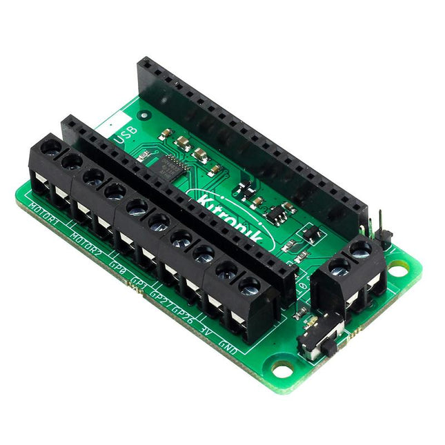
This board allows the Raspberry Pi Pico (connected via pin header) to drive two motors simultaneously with full forward, reverse & stop control, making it ideal for Pico controlled buggy projects. Alternatively, the board can be used to power a stepper motor. The board features the DRV8833 motor driver IC, which has built-in short circuit, over current and thermal protection.
The board has 4 external connections to GPIO pins and a 3 V and GND supply from the Pico. This allows for additional IO options for your buggy builds that can be read or controlled by the Pico. In addition there is an on/off switch and power status LED, allowing you to see at a glance if the board is powered up and save your batteries when your project is not in use.
To use the motor driver board, the Pico should have a soldered pin header and be inserted firmly into the connector. The board produces a regulated supply that is fed into the 40-way connector to power the Pico, removing the need to power the Pico directly. The motor driver board is powered via either screw terminals or a servo style connector.
Kitronik has developed a micro-python module and sample code to support the use of the Motor Driver board with the Pico. This code is available in the GitHub repo.
Features
A compact yet feature-packed board designed to sit at the heart of your Raspberry Pi Pico robot buggy projects.
The board can drive 2 motors simultaneously with full forward, reverse, and stop control.
It features the DRV8833 motor driver IC, which has built-in short circuit, over current and thermal protection.
Additionally, the board features an on/off switch and power status LED.
Power the board via a terminal block style connector.
The 3V and GND pins are also broken out, allowing external devices to be powered.
Code it with MicroPython via an editor such as the Thonny editor.
Dimensions: 63 mm (L) x 35 mm (W) x 11.6 mm (H)
Download
Datasheet
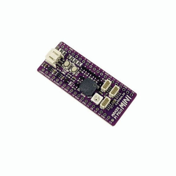
Love the Cytron Maker Pi Pico (SKU 19706) but can't fit it into your project? Now there is the Cytron Maker Pi Pico Mini W. Powered by the awesome Raspberry Pi Pico W, it also inherited most of the useful features from its bigger sibling such as GPIO status LEDs, WS2812B Neopixel RGB LED, passive piezo buzzer, and not forget the user button and reset button. Features Powered by Raspberry Pi Pico W Single-cell LiPo connector with overcharge / over-discharge protection circuit, rechargeable via USB. 6x Status indicator LEDs for GPIOs 1x Passive piezo buzzer (Able to play musical tone or melody) 1x Reset button 1x User programmable button 1x RGB LEDs (WS2812B Neopixel) 3x Maker Ports, compatible with Qwiic, STEMMA QT, and Grove (via conversion cable) Support Arduino IDE, CircuitPython and MicroPython Dimension: 23.12 x 53.85 mm Included 1x Maker Pi Pico Mini W (pre-soldered Raspberry Pi Pico W with preloaded CircuitPython) 3x Grove to JST-SH (Qwiic / STEMMA QT) Cable Downloads Maker Pi Pico Mini Datasheet Maker Pi Pico Mini Schematic Maker Pi Pico Mini Pinout Diagram Official Raspberry Pi Pico Page Getting started with Raspberry Pi Pico CircuitPython for Raspberry Pi Pico Raspberry Pi Pico Datasheet RP2040 Datasheet Raspberry Pi Pico Python SDK Raspberry Pi Pico C/C++ SDK
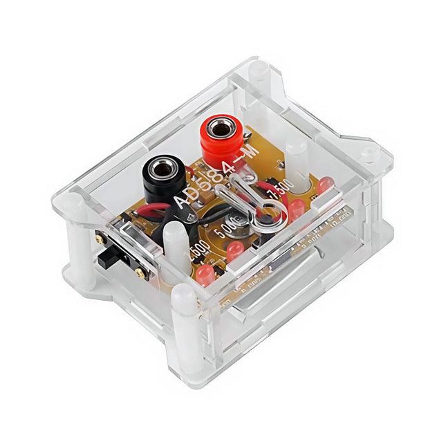
The AD584 4-ch Voltage Reference Module is designed to provide stable and accurate reference voltages of 2.5 V, 5 V, 7.5 V, and 10 V. It incorporates the AD584 integrated circuit, known for its high accuracy and stability.
Features
Multiple Output Voltages: The module can output four different reference voltages (2.5 V, 5 V, 7.5 V, and 10 V) accessible through a single port.
Microcontroller-based Switching: An onboard microcontroller facilitates switching between the four voltage outputs, with LED indicators displaying the active selection.
User-Friendly Operation: A single button allows for easy cycling through the available reference voltages.
Transparent Housing: The module is encased in a transparent housing, offering protection while allowing users to view the internal components.
Power Supply Options: It can be powered via a built-in lithium battery (not included) or through a 5 V DC input. A charging indicator provides status updates during charging.
Output Interface: Equipped with 4mm banana sockets for secure and reliable connections.
Included
1x AD584 4-ch Voltage Reference Module with Housing
Downloads
Datasheet
Specifications
Channels: 3
Total Power: 195 Watts
Max. Voltage: 30 Volts
Max. Current: 3 Amps
Low ripple and noise: <350 μVrms/2 mVpp
Excellent linear regulation rate and load regulation rate
Fast transient response time: <50 μs
Some channels are isolated
Standard OVP/OCP/OTP protection functions
Standard timing output
Built-in V,A,W measurements and waveform display
Independent control for each channel
3.5 inch TFT display
Included
1x Rigol DP832 DC Power Supply
1x Power cord
1x USB cable
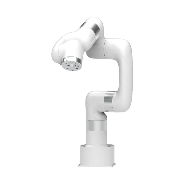
This multi-axis robot perfectly balances power and size.
Features
6 Axis
Payload: 3.5 kg
Reach: 700 mm
Repeatability: 0.1 mm
Max Speed 1000 mm/s
Applications
Machine Tending
Bin Picking
Mobile platform
Lab Automation
Robotic Research
Durable Collaborative robots for your automation
Industrial-grade harmonic drive and servomotors guarantee 24/7 working without stop.
Crafted from Carbon fiber, 15 kg weight makes it possible for easier deployment.
Flexible deployment with safe feature
Hand teaching, lightweight, space-saving and easy to re-deploy to multiple applications without changing your production layout. Perfectly for recurrent tasks.
Collision detection is available for all of our cobots. Your safety is always the top priority.
Graphical interface for beginner-friendly programming
Compatible with various of operation systems, including macOS and Windows.
Web-based technology compatible with all major browsers.
Drag and drop to create your code in minutes.
Powerful and open source SDK at your fingertips
Fully functional open-source Python/C++ SDK provides more flexible programming.
ROS/ROS2 packages are ready-to-go.
Example codes help you to deploy the robotic arm smoothly.
Specifications
UFactory 850
xArm 5
xArm 6
xArm 7
Payload
5 kg
3 kg
5 kg
3.5 kg
Reach
850 mm
700 mm
700 mm
700 mm
Degrees of freedom
6
5
6
7
Repeatability
±0.02 mm
±0.1 mm
±0.1 mm
±0.1 mm
Maximum Speed
1 m/s
1 m/s
1 m/s
1 m/s
Weight (robot arm only)
20 kg
11.2 kg
12.2 kg
13.7 kg
Maximum Speed
180°/s
180°/s
180°/s
180°/s
Joint 1
±360°
±360°
±360°
±360°
Joint 2
-132°~132°
-118°~120°
-118°~120°
-118°~120°
Joint 3
-242°~3.5°
-225°~11°
-225°~11°
±360°
Joint 4
±360°
-97°~180°
±360°
-11°~225°
Joint 5
-124°~124°
±360°
-97°~180°
±360°
Joint 6
±360°
±360°
-97°~180°
Joint 7
±360°
Hardware
Ambient Temperature Range
0-50°C
Power Consumption
Min 8.4 W, Typical 200 W, max 400 W
Input Power Supply
24 V DC, 16.5 A
Footprint
Ø 126 mm
Materials
Aluminum, Carbon Fiber
Base Connector Type
M5x5
ISO Class Cleanroom
5
Robot Mounting
Any
End Effector Communication Protocol
Modbus RTU(rs485)
End Effector I/O
2x DI/2x DO/2x AI/1x RS485
Communication Mode
Ethernet
Included
1x xArm 7 robotic arm
1x AC control box
1x Robotic arm power cable
1x Robotic arm end effector adapter cable
1x Robotic arm signal cable
1x Control box power cable
1x Network cable
1x Mounting tool
1x Quick start guide
Features
Bandwidth: DC-800 KHz
Maximum measurable current: 100 Apk (70.7 Arms)
Max. conductor diameter: 13 mm
Auto & Manual "Zero" function
Directly powered by USB port
Standard BNC interface, compatible with any oscilloscope
Specifications
Bandwidth
DC-800 KHz
Rise time
<= 583 ns
Ranges
10 A / 100 A
Output sensitivity
0.1 V/A (10 A) 0.01 V/A (100 A)
DC accuracy
3% ±50 mA (10 A) 4% ±50 mA (100 A, 500 mA - 40 Apk) 15% (100 A, 40 Apk -100 Apk)
Signal delay
< 150 ns (10 A) < 200ns (100 A)
Current measurement range
50 mA - 10 Apk (10 A) 1 A - 100 Apk (100 A)
Max. Voltage
CAT III 300 V CAT II 600 V
Power supply
DC 5 V
Downloads
Quick Guide
Datasheet
Manual
The Milk-V Duo 256M is an ultra-compact embedded development platform based on the SG2002 chip. It can run Linux and RTOS, providing a reliable, low-cost, and high-performance platform for professionals, industrial ODMs, AIoT enthusiasts, DIY hobbyists, and creators.
This board is an upgraded version of Duo with a memory boost to 256M, catering to applications demanding larger memory capacities. The SG2002 elevates computational power to 1.0 TOPS @ INT8. It enables seamless switching between RISC-V/ARM architectures and supports simultaneous operation of dual systems. Additionally, it includes an array of rich GPIO interfaces such as SPI, UART, suitable for a wide range of hardware development in edge intelligent monitoring, including IP cameras, smart peephole locks, visual doorbells, and more.
SG2002 is a high-performance, low-power chip designed for various product fields such as edge intelligent surveillance IP cameras, smart door locks, visual doorbells, and home intelligence. It integrates H.264 video compression and decoding, H.265 video compression encoding, and ISP capabilities. It supports multiple image enhancement and correction algorithms such as HDR wide dynamic range, 3D noise reduction, defogging, and lens distortion correction, providing customers with professional-grade video image quality.
The chip also incorporates a self-developed TPU, delivering 1.0 TOPS of computing power under 8-bit integer operations. The specially designed TPU scheduling engine efficiently provides high-bandwidth data flow for all tensor processing unit cores. Additionally, it offers users a powerful deep learning model compiler and software SDK development kit. Leading deep learning frameworks like Caffe and Tensorflow can be easily ported to its platform. Furthermore, it includes security boot, secure updates, and encryption, providing a series of security solutions from development, mass production, to product applications.
The chip integrates an 8-bit MCU subsystem, replacing the typical external MCU to achieve cost-saving and power efficiency goals.
Specifications
SoC
SG2002
RISC-V CPU
C906 @ 1 Ghz + C906 @ 700 MHz
Arm CPU
1x Cortex-A53 @ 1 GHz
MCU
8051 @ 6 KB SRAM
Memory
256 MB SIP DRAM
TPU
1.0 TOPS @ INT8
Storage
1x microSD connector or 1x SD NAND on board
USB
1x USB-C for power and data, USB Pads available
CSI
1x 16P FPC connector (MIPI CSI 2-lane)
Sensor Support
5 M @ 30 fps
Ethernet
100 Mbps Ethernet with PHY
Audio
Via GPIO Pads
GPIO
Up to 26x GPIO Pads
Power
5 V/1 A
OS Support
Linux, RTOS
Dimensions
21 x 51 mm
Downloads
Documentation
GitHub
This book is for people who want to understand how AC drives (also known as inverter drives) work and how they are used in industry by showing mainly the practical design and application of drives.
The key principles of power electronics are described and presented in a simple way, as are the basics of both DC and AC motors. The different parts of an AC drive are explained, together with the theoretical background and the practical design issues such as cooling and protection.
An important part of the book gives details of the features and functions often found in AC drives and gives practical advice on how and where to use these. Also described is future drive technology, including a matrix inverter.
The mathematics is kept to an essential minimum. Some basic understanding of mechanical and electrical theory is presumed, and a basic knowledge of single andthree phase AC systems would be useful.
Anyone who uses or installs drives, or is just interested in how these powerful electronic products operate and control modern industry, will find this book fascinating and informative.
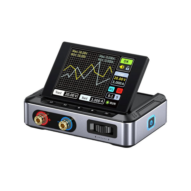
The FNIRSI DPS150 is a high-performance adjustable DC power supply that features a USB-C input interface and multiple power supply modes, allowing precise adjustment of output voltage (0-30 V) and current (0-5 A).
It provides efficient, low-consumption, and stable output, equipped with multiple safety protection functions including overvoltage, overcurrent, overload, overheating, and reverse connection. It can be flexibly applied to serial connection of multiple devices, with rich and user-friendly display and operation, compact and portable design, meeting various application needs.
Features
30 V, 5 A, 150 W variable DC power with 0.01 V, 0.001 A precision, CC/CV modes, and <20 mV ripple to protect sensitive electronics.
Supports PC, QC, and DC inputs with programmable outputs and 6 preset voltage/current settings.
Compatible with 4 mm banana plugs, U-shaped terminals, and copper wires for various equipment.
8 safety mechanisms including overvoltage, current, short circuit, and overheating protection.
2.8-inch HD IPS screen with 90° flip, numerical and curve displays for easy monitoring.
Small, space-saving design for use in labs, repairs, and DIY projects.
Specifications
Input Voltage
5~32 V DC
Input Current
100 mA-5 A
Output Voltage
0-30 V
Output Current
0~5 A
Output Power
0-150 W
Input Way
PD fast charger
QC fast charger
Power bank
DC power adapters
Operating Environment
0-40°C
Load Regulation
0.49%
Full Load Efficiency
96.30%
Display
2.8 inch (320 x 240)
Dimensions
106 x 76 x 28 mm
Weight
178 g
Included
1x DPS150 Power Supply
2x Alligator clip wires (black & red)
1x Micro USB cable
1x Manual
Downloads
Manual
Firmware V0.0.1
The FNIRSI DPS150 is a high-performance adjustable DC power supply that features a USB-C input interface and multiple power supply modes, allowing precise adjustment of output voltage (0-30 V) and current (0-5 A).
It provides efficient, low-consumption, and stable output, equipped with multiple safety protection functions including overvoltage, overcurrent, overload, overheating, and reverse connection. It can be flexibly applied to serial connection of multiple devices, with rich and user-friendly display and operation, compact and portable design, meeting various application needs.
Features
30 V, 5 A, 150 W variable DC power with 0.01 V, 0.001 A precision, CC/CV modes, and <20 mV ripple to protect sensitive electronics.
Supports PC, QC, and DC inputs with programmable outputs and 6 preset voltage/current settings.
Compatible with 4 mm banana plugs, U-shaped terminals, and copper wires for various equipment.
8 safety mechanisms including overvoltage, current, short circuit, and overheating protection.
2.8-inch HD IPS screen with 90° flip, numerical and curve displays for easy monitoring.
Small, space-saving design for use in labs, repairs, and DIY projects.
Specifications
Input Voltage
5~32 V DC
Input Current
100 mA-5 A
Output Voltage
0-30 V
Output Current
0~5 A
Output Power
0-150 W
Input Way
PD fast charger
QC fast charger
Power bank
DC power adapters
Operating Environment
0-40°C
Load Regulation
0.49%
Full Load Efficiency
96.30%
Display
2.8 inch (320 x 240)
Dimensions
106 x 76 x 28 mm
Weight
178 g
Included
1x DPS150 Power Supply
2x Alligator clip wires (black & red)
1x C2C PD charging cable
1x 100 W PD GaN Adapter (EU)
1x Micro USB cable
1x Manual
Downloads
Manual
Firmware V0.0.1