Search results for "boite OR a OR idees OR pour OR le OR raspberry OR pi"
-
Raspberry Pi Foundation Bumper for Raspberry Pi 5
The Raspberry Pi Bumper is a snap-on silicone cover that protects the bottom and edges of the Raspberry Pi 5. Features One-piece flexible silicone rubber bumper Enables easy access to the power button Mounting holes remain accessible underneath the bumper Downloads Datasheet
€ 3,50
Members identical
-
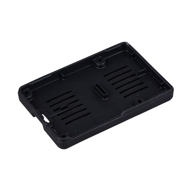
Raspberry Pi Foundation Official Case for Raspberry Pi Zero
The case consists of two parts. It has a standard base featuring a cut-out to allow access to the GPIO, and a choice of three lids: a plain lid, a GPIO lid (allowing access to the GPIO from above), and a camera lid (which, when used with the short camera cable supplied, allows the Raspberry Pi Camera or Camera Noir to be fitted neatly inside it). Included 1x base 3x lids (plain, GPIO, camera) 1x short camera cable 4x rubber feet
€ 7,95
Members identical
-
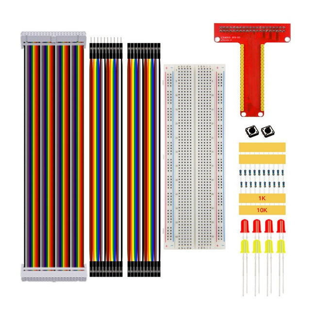
Kuongshun Raspberry Pi T-Type Kit
Features Suitable for Raspberry Pi + GPIO Extension Board Exquisite appearance DIY operation Specifications Size of GPIO Extension Board: 7.5 x 6 cm (3 x 2.4') Size of Breadboard: 16.5 x 5.5 x 1 cm (6.5 x 2.2 x 0.4') Included 1x GPIO Extension Board 1x Breadboard 1x 40P Pin Connect Line 8x 1K Resistor 8x 10K Resistor 4x LED (yellow) 4x LED (red) 4x Key 10x 25 mm Jumper Wires A 10x 25 mm Jumper Wires B
€ 14,95€ 9,95
Members identical
-
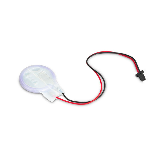
Raspberry Pi Foundation RTC Battery for Raspberry Pi 5
The power-management IC used on Raspberry Pi 5 integrates a real-time clock, and charging circuitry for a button cell which can power the clock while main power is disconnected. This Panasonic ML-2020 lithium manganese dioxide battery with a two-pin plug and a double-sided adhesive pad can be connected directly to the battery connector of the Raspberry Pi 5 and attached to the inside of a case or another convenient location.
€ 7,95
Members identical
-
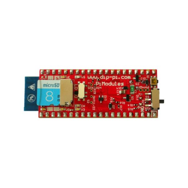
Pi Modules DiP-Pi Pico PIoT for Raspberry Pi Pico
The DiP-Pi PIoT is an Advanced Powered, WiFi connectivity System with sensors embedded interfaces that cover most of possible needs for IoT application based on Raspberry Pi Pico. It can supply the system with up to 1.5 A @ 4.8 V delivered from 6-18 VDC on various powering schemes like Cars, Industrial plant etc., additionally to original micro-USB of the Raspberry Pi Pico. It supports LiPo or Li-Ion Battery with Automatic Charger as also automatic switching from cable powering to battery powering or reverse (UPS functionality) when cable powering lost. Extended Powering Source (EPR) is protected with PPTC Resettable fuse, Reverse Polarity, as also ESD. The DiP-Pi PIoT contains Raspberry Pi Pico embedded RESET button as also ON/OFF Slide Switch that is acting on all powering sources (USB, EPR or Battery). User can monitor (via Raspberry Pi Pico A/D pins) battery level and EPR Level with PICO’s A/D converters. Both A/D inputs are bridged with 0402 resistors (0 OHM) therefore if for any reason user needs to use those Pico pins for their own application can be easy removed. The charger is automatically charging connected battery (if used) but in addition user can switch charger ON/OFF if their application needs it. DiP-Pi PIoT can be used for cable powered IoT systems, but also for pure Battery Powered System with ON/OFF. Each powering source status is indicated by separate informative LEDs (VBUS, VSYS, VEPR, CHGR, V3V3). User can use any capacity of LiPo or Li-Ion type; however, must take care to use PCB protected batteries with max discharge current allowed of 2 A. The embedded battery charger is set to charge battery with 240 mA current. This current is set by resistor so if user need more/less can himself to change it. The DiP-Pi PIoT is also equipped with WiFi ESP8266 Clone module with embedded antenna. This feature open a wide range of IoT applications based on it. In Addition to all above features DiP-Pi PIoT is equipped with embedded 1-wire, DHT11/22 sensors, and micro–SD Card interfaces. Combination of the extended powering, battery, and sensors interfaces make the DiP-Pi PIoT ideal for IoT applications like data logger, plants monitoring, refrigerators monitoring etc. DiP-Pi PIoT is supported with plenty of ready to use examples written in Micro Python or C/C++. Specifications General Dimensions 21 x 51 mm Raspberry Pi Pico pinout compatible Independent Informative LEDs (VBUS, VSYS, VEPR, CHGR, V3V3) Raspberry Pi Pico RESET Button ON/OFF Slide Switch acting on all powering sources (USB, EPR, Battery) External Powering 6-18 VDC (Cars, Industrial Applications etc.) External Power (6-18 VDC) Level Monitoring Battery Level Monitoring Inverse Polarity Protection PPTC Fuse Protection ESD Protection Automatic Battery Charger (for PCB protected LiPo, Li-Ion – 2 A Max) Automatic/User Control Automatic Switch from Cable Powering to Battery Powering and reverse (UPS Functionality) Various powering schemes can be used at the same time with USB Powering, External Powering and Battery Powering 1.5 A @ 4.8 V Buck Converter on EPR Embedded 3.3 V @ 600 mA LDO ESP8266 Clone WiFi Connectivity ESP8266 Firmware Upload Switch Embedded 1-wire Interface Embedded DHT-11/22 Interface Powering Options Raspberry Pi Pico micro-USB (via VBUS) External Powering 6-18 V (via dedicated Socket – 3.4/1.3 mm) External Battery Supported Battery Types LiPo with protection PCB max current 2A Li-Ion with protection PCB max current 2A Embedded Peripherals and Interfaces Embedded 1-wire interface Embedded DHT-11/22 Interface Micro SD Card Socket Programmer Interface Standard Raspberry Pi Pico C/C++ Standard Raspberry Pi Pico Micro Python Case Compatibility DiP-Pi Plexi-Cut Case System Monitoring Battery Level via Raspberry Pi Pico ADC0 (GP26) EPR Level via Raspberry Pi Pico ADC1 (GP27) Informative LEDs VB (VUSB) VS (VSYS) VE (VEPR) CH (VCHR) V3 (V3V3) System Protection Direct Raspberry Pi Pico Hardware Reset Button ESD Protection on EPR Reverse Polarity Protection on EPR PPTC 500 mA @ 18 V fuse on EPR EPR/LDO Over Temperature protection EPR/LDO Over Current protection System Design Designed and Simulated with PDA Analyzer with one of the most advanced CAD/CAM Tools – Altium Designer Industrial Originated PCB Construction 2 ozcopper PCB manufactured for proper high current supply and cooling 6 mils track/6 mils gap technology 2 layers PCB PCB Surface Finishing – Immersion Gold Multi-layer Copper Thermal Pipes for increased System Thermal Response and better passive cooling Downloads Datasheet Manual
€ 21,95€ 14,95
Members identical
-
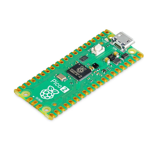
Raspberry Pi Foundation Raspberry Pi Pico 2
The Raspberry Pi Pico 2 is a new microcontroller board from the Raspberry Pi Foundation, based on the RP2350. It features a higher core clock speed, double the on-chip SRAM, double the on-board flash memory, more powerful Arm cores, optional RISC-V cores, new security features, and upgraded interfacing capabilities. The Raspberry Pi Pico 2 offers a significant boost in performance and features while maintaining hardware and software compatibility with earlier members of the Raspberry Pi Pico series. The RP2350 provides a comprehensive security architecture built around Arm TrustZone for Cortex-M. It incorporates signed boot, 8 KB of antifuse OTP for key storage, SHA-256 acceleration, a hardware TRNG, and fast glitch detectors. The unique dual-core, dual-architecture capability of the RP2350 allows users to choose between a pair of industry-standard Arm Cortex-M33 cores and a pair of open-hardware Hazard3 RISC-V cores. Programmable in C/C++ and Python, and supported by detailed documentation, the Raspberry Pi Pico 2 is the ideal microcontroller board for both enthusiasts and professional developers. Specifications CPU Dual Arm Cortex-M33 or dual RISC-V Hazard3 processors @ 150 MHz Memory 520 KB on-chip SRAM; 4 MB on-board QSPI flash Interfaces 26 multi-purpose GPIO pins, including 4 that can be used for AD Peripherals 2x UART 2x SPI controllers 2x I²C controllers 24x PWM channels 1x USB 1.1 controller and PHY, with host and device support 12x PIO state machines Input power 1.8-5.5 V DC Dimensions 21 x 51 mm Downloads Datasheet (Pico 2) Datasheet (RP2350)
€ 5,95
Members identical
-
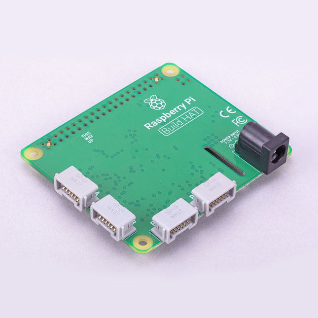
Raspberry Pi Foundation Raspberry Pi Build HAT
Build robust, intelligent machines that combine Raspberry Pi computing power with LEGO components. The Raspberry Pi Build HAT provides four connectors for LEGO Technic motors and sensors from the SPIKE Portfolio. The available sensors include a distance sensor, a color sensor, and a versatile force sensor. The angular motors come in a range of sizes and include integrated encoders that can be queried to find their position. The Build HAT fits all Raspberry Pi computers with a 40-pin GPIO header, including – with the addition of a ribbon cable or other extension device — Raspberry Pi 400. Connected LEGO Technic devices can easily be controlled in Python, alongside standard Raspberry Pi accessories such as a camera module. Features Controls up to 4 motors and sensors Powers the Raspberry Pi (when used with a suitable external PSU) Easy to use from Python on the Raspberry Pi
€ 29,95€ 14,95
Members identical
-
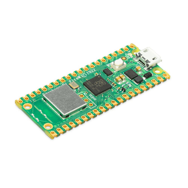
Raspberry Pi Foundation Raspberry Pi Pico W
Raspberry Pi Pico W is a microcontroller board based on the Raspberry Pi RP2040 microcontroller chip. The RP2040 microcontroller chip ('Raspberry Silicon') offers a dual-core ARM Cortex-M0+ processor (133 MHz), 256 KB RAM, 30 GPIO pins, and many other interface options. In addition, there is 2 MB of on-board QSPI flash memory for code and data storage. Raspberry Pi Pico W has been designed to be a low cost yet flexible development platform for RP2040 with a 2.4 GHz wireless interface using an Infineon CYW43439. The wireless interface is connected via SPI to the RP2040. Features of Pico W RP2040 microcontroller with 2 MB of flash memory On-board single-band 2.4 GHz wireless interfaces (802.11n) Micro USB B port for power and data (and for reprogramming the flash) 40 pin 21 x 51 mm 'DIP' style 1 mm thick PCB with 0.1' through-hole pins also with edge castellations Exposes 26 multi-function 3.3 V general purpose I/O (GPIO) 23 GPIO are digital-only, with three also being ADC capable Can be surface mounted as a module 3-pin ARM serial wire debug (SWD) port Simple yet highly flexible power supply architecture Various options for easily powering the unit from micro USB, external supplies or batteries High quality, low cost, high availability Comprehensive SDK, software examples and documentation Features of the RP2040 microcontroller Dual-core cortex M0+ at up to 133 MHz On-chip PLL allows variable core frequency 264 kByte multi-bank high performance SRAM External Quad-SPI Flash with eXecute In Place (XIP) and 16 kByte on-chip cache High performance full-crossbar bus fabric On-board USB1.1 (device or host) 30 multi-function general purpose I/O (four can be used for ADC) 1.8-3.3 V I/O voltage 12-bit 500 ksps analogue to digital converter (ADC) Various digital peripherals 2x UART, 2x I²C, 2x SPI, 16x PWM channels 1x timer with 4 alarms, 1x real time clock 2x programmable I/O (PIO) blocks, 8 state machines in total Flexible, user-programmable high-speed I/O Can emulate interfaces such as SD card and VGA Note: Raspberry Pi Pico W I/O voltage is fixed at 3.3 V. Downloads Datasheet Specifications of 3-pin Debug Connector
€ 7,95
Members identical
-

JOY-iT Passive Cooling for Raspberry Pi (Heatsink)
Aluminium Heatsink Set for Raspberry Pi with pre-applied tape for easy installation 1 piece: 14 x 15 x 5 mm 2 pieces: 8 x 8 x 5 mm
€ 3,95
Members € 3,56
-
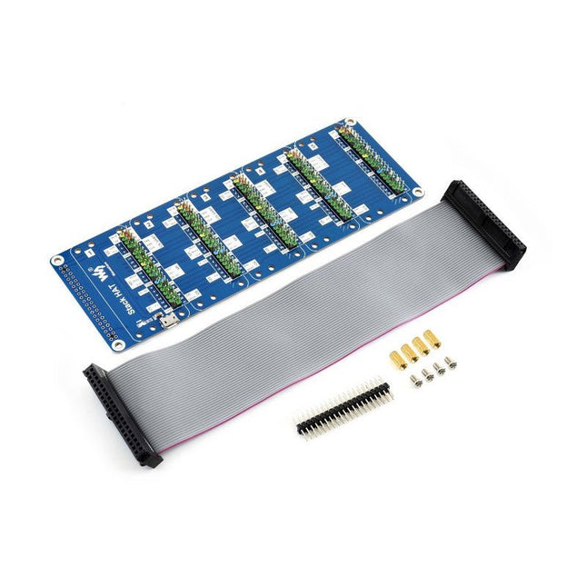
Waveshare Waveshare Stack HAT for Raspberry Pi
This is an I/O expansion kit designed for Raspberry Pi, which provides 5 sets of 2x20 pinheaders, that means a handy way to 'stack' multi different HATs together, and use them as a specific combination / project. Features Standard Raspberry Pi connectivity, directly pluggable OR through ribbon cable 5 sets of 2x20 pinheaders, connect multi HATs together USB external power port, provides enough power supply for multi HATs Clear and descriptive pin labels for easy use Reserved jumper pads on the bottom side, pin connections are changeable by soldering, to avoid pin conflicts Note: make sure there are no any pin conflicts between the HATs you want to use together before connecting. Specifications Dimensions: 183 × 65 mm Mounting hole size: 3 mm Included 1x Stack HAT 1x Ribbon cable 40-Pin 1x 2x20 male pinheader 1x RPi screws pack (4pcs) x1
€ 17,95€ 8,95
Members identical
-

SparkFun SparkFun Servo pHAT for Raspberry Pi
Thanks to its I²C capabilities, this PWM HAT saves the Raspberry Pi's GPIO pins, allowing you to use them for other purposes. The Servo pHAT also adds a serial terminal connection, which will allow you to bring up a Raspberry Pi without having to hook it up to a monitor and keyboard. We have provided a Qwiic connector for easy interfacing with the I²C bus using the Qwiic system and a 4-pin header to connect to the Sphero RVR. Power to the SparkFun Servo pHAT can be supplied through a USB-C connector. This will power either the servo motors only or power the servo motors and the Raspberry Pi that is connected to the HAT. We switched to USB-C to allow you to bring more current to your servos than ever before. This USB-C connector can also hook up the Pi via serial port connection to avoid having to use a monitor and keyboard for setting up the Pi. To supply power only to the servo power rail (and not the Pi's 5V power rail), you need to cut a small trace on the isolation jumper. Doing this allows you to drive heavier loads coming from multiple or larger servos. We've even added power protection circuits to the design to avoid damage to power sources. Each of this pHAT's 16 servo motor pin headers has been spaced out to the standard 3-pin servo pinout (ground, 5V, signal) to make it easier to attach your servo motors. The Servo pHAT is the same size and form factor as a Raspberry Pi Zero and Zero W, but it can also operate with a regular Raspberry Pi. Features 16 PWM channels, controllable over I²C Qwiic connector 4-pin RVR header for connection to Sphero RVR USB-C connector 40-pin GPIO header for connection to Raspberry Pi CH340C USB Serial SOIC16 Updated logic level conversion circuitry Power protection circuits
€ 10,95
Members € 9,86


-
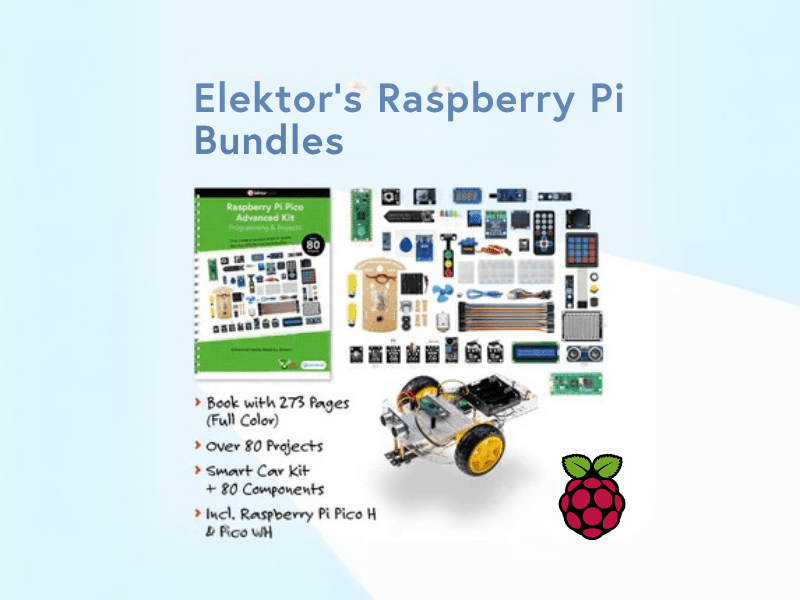
, by Lobna Belarbi Elektor’s Raspberry Pi Bundles: From Beginner-Friendly to Advanced Kits
Find the Perfect Raspberry Pi Bundle for Your Skill Level Whether you're a beginner eager to explore the world of Raspberry Pi or an advanced...
